UNIVERSITI TEKNIKAL MALAYSIA MELAKA (UTeM)
FORCE ANALYSIS ON ROBOTIC
DEBURRING PROCESS
Thesis submitted in accordance with the partial requirements of the Universiti Teknikal Malaysia Melaka for the
Bachelor of Manufacturing Engineering (Robotic and Automation)
By
MOHAMMAD SYAZWAN BIN OMAR
B 050410195
UTeM Library (Pind.1/2007)
UNIVERSITI TEKNIKAL MALAYSIA MELAKA
BORANG PENGESAHAN STATUS LAPORAN PSM
JUDUL:
FORCE ANALYSIS ON ROBOTIC DEBURRING PROCESS
SESI PENGAJIAN: Semest er 2 2007/ 2008
Saya MOHAMMAD SYAZWAN BIN OMAR
mengaku membenarkan laporan PSM / t esis (Sarj ana/ Dokt or Falsaf ah) ini disimpan di Perpust akaan Universit i Teknikal Malaysia Melaka (UTeM) dengan syarat -syarat kegunaan sepert i berikut :
1. Laporan PSM / t esis adalah hak milik Universit i Teknikal Malaysia Melaka dan
penulis.
2. Perpust akaan Universit i Teknikal Malaysia Melaka dibenarkan membuat salinan
unt uk t uj uan pengaj ian sahaj a dengan izin penulis.
3. Perpust akaan dibenarkan membuat salinan laporan PSM / t esis ini sebagai bahan
pert ukaran ant ara inst it usi pengaj ian t inggi.
4. *Sila t andakan (√)
SULIT
TERHAD
√ TIDAK TERHAD
(Mengandungi maklumat yang berdarj ah keselamat an at au kepent ingan Malaysia yang t ermakt ub di dalam AKTA RAHSIA RASMI 1972)
(Mengandungi maklumat TERHAD yang t elah dit ent ukan oleh organisasi/ badan di mana penyelidikan di j alankan)
APPROVAL
This thesis submitted to the senate of UTeM and has been accepted as fulfillment of the requirement for the Bachelor of Manufacturing Engineering (Robotic and Automation)
with honors. The members of the supervisory committee are as follow:
……….. ( En Khairol Anuar Bin Rakiman )
Main supervisor
DECLARATION
I hereby, declared this thesis entitled “FORCE ANALYSIS ON ROBOTIC
DEBURRING PROCESS” is the results of my own research except as cited in
references.
Signature : ……….
Author’s Name : MOHAMMAD SYAZWAN BIN OMAR
ABSTRACT
ABSTRAK
ACKNOWLEDGMENT
First of all, I want to thank The Almighty God because of His permission that gives me strength to finish this report with successfully even many difficulties that had come. For my beloved parents Hj Omar bin Musa, Hjh Wan Zainab bt. Wan Abdullah and all my family, thanks for all support that have been given in finishing this PSM.
Then, my PSM supervisor Mr. Khairol Anuar bin Rakiman that always gave guidance for me during this period and help me to complete this project. Beside that, I want to take these opportunities to thank to my entire lecture and technicians that teach me all the useful knowledge that I had used during this PSM.
TABLE OF CONTENTS
1.2 Problem statement 2
1.3 Objectives 2
1.4 Scope of project 3
1.5 Project outline 3
2. LITERATURE REVIEW 4
2.1 Introduction 4
2.2 Previous achievement 6
2.3 Force sensor background 15
2.3.1 Definition 15
2.4 Theory of burrs formation 15
2.4.1 Definition 15
2.4.2 Burrs formation 15
2.5 Deburring process 20
2.6 Deburring problems 28
3. METHODOLOGY 29
3.2 Research Tools 30
3.2.1 Internet 31
3.2.2 Manual and books 31
3.2.3 Article & Journals 31
3.3 Process planning 32
3.3.1 Topic selection 33
3.3.2 Proposal 33
3.3.3 Data collection 33
3.3.4 Designing method 34
3.3.5 Experiment setup 34
3.3.6 Result analysis 34
3.3.7 Discussion and conclusion 35
3.3.8 Presentation and report writing 35
3.3.8.1 Introduction 35
3.3.8.2 Literature review 36
3.3.8.3 Methodology 36
3.3.8.4 Result and analysis 36
3.3.8.5 Discussion 37
3.3.8.6 Conclusion and suggestion 37
3.4 Project Tools 37
3.4.1 Personal computer 38
3.4.2 COMAU robot 38
3.4.2.1 Technical specification 39
3.4.2.2 CG4 controller 41
3.4.3 ATI Multi-Axis Force/Torque sensor 41
3.4.3.1 Mechanical description of the force and torque sensor 43
3.4.4 Material 45
3.4.5 Deburring tool 46
3.5 Experiment setup 48
4.1 Introduction 49
4.2 Equipments 50
4.3 Experiment setup 52
4.3.1 Expected method 53
4.3.1.1 COMAU’s programming 53
4.3.1.2 ATI Multi-Axis Force/Torque Sensor Setup 58
4.3.2 Alternative method 58
4.4 Experiment 62
4.5 Results 64
5. RESULTS AND ANALYSIS 65
5.1 Introduction 65
5.2 Expected result 65
5.2.1 Material analysis 65
5.3 Actual result 68
5.3.1 Material analysis 68
5.3.1.1 Aluminium 68
5.3.1.2 Mild steel 70
5.3.1.3 Acrylic 71
6. DISCUSSIONS 73
7. CONCLUSION AND IMPROVEMENTS 75
7.1 Conclusions 75
7.2 Improvements 77
REFERENCES 78
APPENDICES
LIST OF FIGURES
No Name Page
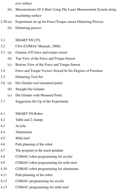
2.1 Schematic of Robotic Surface Finish System 6
2.2 Sensorization System 7
2.3 Force/Torque Sensor Setup 7
2.4 N-Joint Manipulator Mounted on a Force/Torque Sensor 8 2.5 A PUMA 550 Manipulator Mounted on a Six-Axis Force/Torque
Sensor
9
2.6 Multi Degree of Freedom Robot Manipulator 10
2.7 Schematic of Force Control System 11
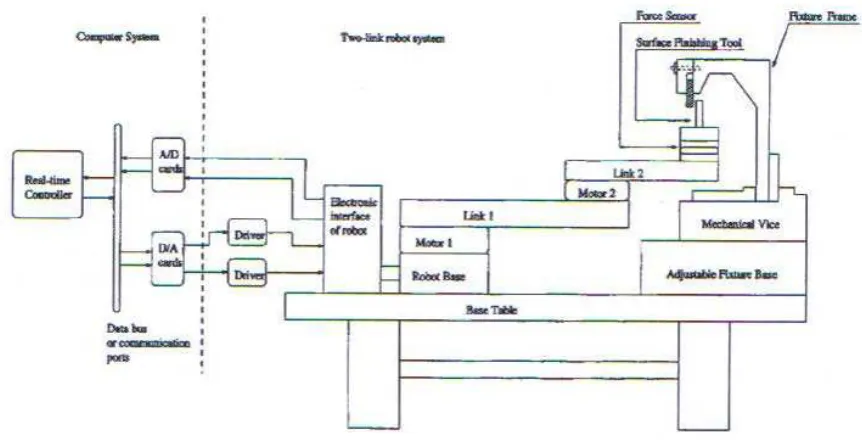
2.8 Schematic of Deburring Experiment on a Superalloy Material 13 2.9 Experimental System for Robotic Deburring-Industrial Robot Manutec
R3 and Its Active End-Effector
14
2.10 Types of Burrs 16
2.11 Types of Burrs in Face Milling 17
2.12 Burr Length and Thickness 18
2.13 Typical Profile of a Burr on a Part Edge 18
2.14 Configuration of Automated Deburring Operation 19 2.15 The Tool Front Bevel Angle γ for a Single Tool Tooth in Contact With
The Surface
22
2.16 (a) The tool path feedrate direction coincides with the direction of the peripherical velocity of the tool tooth in contact with the surface
22
(b) The tool path feedrate is opposite to the peripherical velocity of the tool tooth in contact with the surface
23
2.17 (a) Surface Finish Mode 1 24
(b) Surface Finish Mode 2 24
2.18 Forces acting on the cutting tool and measured by the force sensor during a machining task with offset between the sensor and the mill
25
exit surface
(b) Measurements Of A Burr Using The Laser Measurement System along machining surface
26
2.20 (a) Experiment set up for Force/Torque sensor Deburring Process 27
(b) Deburring process 27 3.4 Force and Torque Vectors Sensed In Six Degrees of Freedom 43
3.5 Deburring Tool Set 46
4.8 COMAU robot programming for acrylic 55
4.9 COMAU robot programming for mild steel 56
4.10 COMAU robot programming for aluminium 57
4.11 Path planning of the robot 58
4.12 COMAU programming for acrylic 59
4.14 COMAU programming for aluminium 60 4.15 Cutting surface area, with 45º chamfer on the workpiece edge 61 4.16 Illustration of deburring process, Vs = wheel speed; Vw = federate; ar =
depth of cut; D = wheel diameter; fn = normal force; ft = tangential
force; f = resultant force
61
4.17 The experiment setup of robot deburring 62
4.18 The deburring process 63
5.1 The profile surface finish for aluminium 69
5.2 The profile surface finish for mild steel 70
LIST OF DIAGRAM
No Name Page
3.1 Project Planning Flow Chart 32
4.1 The process flow of the experiment 49
LIST OF TABLE
No Name Page
3.1 Family of COMAU Robot [25]. 39
3.2 Technical Specification of COMAU Robot (COMAU Manuals, 2006) 40 3.3 Specification of ATI Multi-Axis Force/Torque sensor 44
3.4 The Material for Straight Line Path Planning 45
3.5 The Material for curve Line Path Planning 45
LIST OF GRAPH
No Name Page
5.1 Graph for Tensile Strength vs. selected Material 66 5.2 Graph for modulus of Elasticity vs. Selected Material 66
5.3 Graph for Shear Modulus vs. Selected Material 67
5.4 The graph of surface finish for aluminium 69
5.5 The graph of surface finish for mild steel 71
CHAPTER 1
INTRODUCTION
1.1 Background
Nowadays, robotic application is already familiar with the industrial field. It helps human to do lots of certain task that cannot do by human. This integration between robots and human are very useful in the human life.
In industrial, there are many tasks that require mechanical interactions with the environment, such as assembly, grinding, or deburring. It is necessary to control this interaction force if the task is to be performed successfully.
The forces and torques that encountered with the robot arm can be measured by using force/torque sensor. It includes joint force sensing, wrist force sensing, and finger force sensing.
The advantage of measuring arm joint forces indirectly is that a separate system of force sensors is not required. The joint forces are simply determined by measuring load variables that already exist in the system.
To get accurate force information, one must evaluate things like the inertial forces created through arm movement, joint friction, and the load of the arm itself.
1.2 Problem statement
Most of the robot tasks require contact with the surrounding environment. That interaction generates contact and surface forces that should be controlled in order to finish the task correctly. Those contact forces depend on the stiffness of the tool and working objects, and surface of the material. It should be properly controlled.
The difference of the mechanical properties effected the measurement of the force and torque sensor. It is cause of the strength of the material. The force torque sensor is attached at the end of six degree of freedom (DOF). It is most suitable part to place the force torque sensor.
In surface finish process, the surface is cleaned from the burr or thin. This operation is integrating force torque sensor at the end of end-effector. These sensors allow the measurement of the force between the workpiece and the surrounding environment. Surface finish has to done in order to get good product, safety, etc.
1.3 Objectives
The main objectives of this project are:
1.3.1 To integrate particular application of force/torque sensor with robotic application
1.3.2 To understand the force behavior in the surface finish process
1.4 Scope of the project
The scopes of the project are:
1.4.1 Do planning for the experiment of setup for robotic surface finish process base on the force/torque sensor by using some different material selection 1.4.2 Design the path planning for the experiment
1.4.3 Investigate the problem occur in experimental setup planning
1.4.4 Do analysis on the result of force and torque especially for different material
1.5 Project outline
This report is split into seven chapters. The chapter is described as follows:
Chapter 1 is discussing the objective, scope and problem statement.
Chapter 2 is relates the literature review to the variety of uses and application of
force torque sensor in surface finish process.
Chapter 3 is described the proposed methodology in the experimental setup. It
includes the proper and optional methodology.
Chapter 4 is discussing planning the experimental setup.
Chapter 5 is shows the result from the experiment.
Chapter 6 is analyzing and discussion of the data. Make a comparison between
theoretical and the actual result.
Chapter 7 is summarizes the overall analysis of the study and suggests tasks that
CHAPTER 2
LITERATURE REVIEW
2.1Introduction
Nowadays, robotic is widely used around the world. It used to help people do the job that cannot do by human kind. According to the Robot Institute of America (1979), robot is “A reprogrammable, multifunctional manipulator designed to move materials, parts, tools, or specialized devices through various programmed motions for the performance of a variety of tasks.”
Force is one of the important elements in human life. According to the Webster Dictionary, force is “Any physical cause capable of modifying the condition of movement or of rest of a body, or of deforming it.” It also define as “A torque exerted on a gimbal, gyro rotor or accelerometer proof mass, usually as a result of applied electrical excitations exclusive of torquer command signals.”
Force sensor is one of the main elements in the robot system. It plays important rules in robot mechanism. It will be function as a receptor in human body.
2.2Previous Achievement
The use of robotic manipulators has been growing up dramatically in the last decades. Common applications range from the assembling and welding of different parts in the automotive industry to the manipulation of unknown objects in space missions. The broad spectrum of applications has lead to a quite big number of different and specific designs for such robotic manipulators. Main differences are found in their architectures: number and type of degrees of freedom (DOF), dimensions of its links, actuators or sensors employed.
There are few types of finishing process. It includes grinding, chamfering, polishing, and deburring. All these types of finishing process are supposed to shape a part to its desired geometry.
Figure 2.2: Sensorization System (Ricardo Araújo et all, 2002)
In this section, a set of software tools designed to program, control and monitor the industrial robot (ABB IRB 6400). The main objective is to design tools to add force control capabilities to the original setup (robot and controller). A PC based wrist mounted force/torque sensor (from JR3 Inc.) was installed on the robot. The basic setup is shown on Figure 2.2. The software is divided into four main parts which are robot communication software, force/torque sensor access and configuration software, connectivity to windows applications and force control application software.
Figure 2.3 shows the force/torque sensor setup. The computer will control the robot position. Sometimes the robot motion will not follow the direction and instruction that had programmed before. In order to overcome this situation, the computer will be act to make robot motion corrections. It also controlled the forces and torques whiles the deburring process in progress.
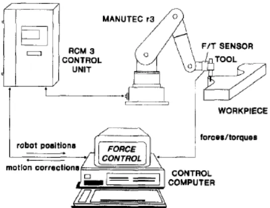
Figure 2.4: N-Joint Manipulator Mounted on a Force/Torque Sensor (Liu.G. et all, 1998)
An n-joint manipulator mounted on a six-axis base force/torque sensor as shown in Figure 2.4. The manipulator is mounted on a base force/torque sensor. Sensor measurements and joint velocities recorded during manipulator motion are used to identify the inertial parameters.
The sensor measurements are used to identify the inertial parameters. The manipulator has n+1 links, where link 0 and link n is the base and the terminal link, respectively. The wrench measured by the base force sensor is denoted as Ws. (Liu.G. et all, 1998).
unmodeled joint friction and actuator dynamics. A base-mounted force/torque sensor has been used to estimate mass properties of a manipulator statically.
The manipulator is mounted on a six-axis force torque sensor. Sensor measurements and joint velocities recorded during manipulator motion are used to identify the inertial parameters. The inertial parameters of robot manipulators can be estimated using the manipulator’s joint torques and forces along with the joint positions and velocities. A major difficulty with this method is that the joint force/torque estimation accuracy is limited by unmodeled joint friction and actuator dynamics.
The robot manipulator is mounted on an external base force/torque sensor. The force torque sensor measures a wrench that corresponds only to the forces and torques effectively applied to the manipulator’s links. (Liu.G. et all, 1998)
Figure 2.5: A PUMA 550 Manipulator Mounted on a Six-Axis Force/Torque Sensor (Liu.G. et all, 1998)
AMTI six-axis force/torque sensor as shown in Figure 2.5. Only the first two joints of the PUMA were actuated, in order to reduce model complexity. The other joints which are joints three, four, and five were immobilized.
The base force/torque sensor is external to the manipulator. The same sensor can be used for parameter estimation for different robot manipulators. The accuracy depends on the measurement accuracy of the force/torque sensor.
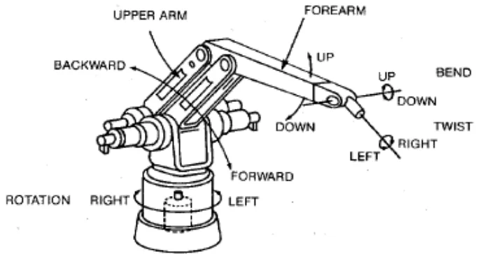
Figure 2.6: Multi Degree of Freedom Robot Manipulator (Stephien et al, 1987)
As a starting point for developing a multi-degree-of freedom force controlled manipulator, force control was implemented on single axes of the robot. The five robot axes, shown in Figure 2.6, may be classified into two types: resonant and non resonant. Resonant axes include rotation, upper arm, and forearm exhibit significant dynamic coupling between motor and load through compliant harmonic drives. Non resonant axes which are twist and bend do not exhibit such coupling.