PJP/2012/FKP(9C)/S01012
E - PREVENTIVE MAINTENANCE
WARNING SYSTEM
PRINCIPAL RESEARCHER
ABDUL RAHIM BIN SAMSUDIN
FAKULTI KEJURUTERAAN PEMBUATAN
UNIVERSITI TEKNIKAL MALAYSIA MELAKA
i
PROJECT COMPLETION REPORT
FOR
(SHORT TERM) RESEARCH GRANT
E - PREVENTIVE MAINTENANCE
WARNING SYSTEM
Principal Researcher : ABDUL RAHIM BIN SAMSUDIN
Co-Researchers : 1. Assoc. Prof. Ir. Dr. Sivarao Subramonian 2. Vigneswara Rao a/l Gannapathy
3. Wahyono Sapto Widodo
4. Safiza Suhana Binti Kamal Baharin
Project Code No. : PJP/2012/FKP(9C)/S01012
Report Submission Date : 9 December 2013
ii
ABSTRAK
iii
ABSTRACT
iv
ACKNOWLEDGEMENT
v
TABLE OF CONTENT
Abstrak ii
Abstract iii
Acknowledgement iv
Table of Content v
List of Tables viii
List of Figures ix
List of Abbreviations, Symbols and Nomenclature xi
CHAPTER 1: INTRODUCTION 1
1.1 Project Background 1
1.2 Problem Statement 2
1.3 Objective of Project 3
1.4 Scope 3
1.5 Maintenance Tools 3
1.5.1 Revolution counter 3
1.5.2 Maintenance 4
1.5.3 Preventive Maintenance 5
1.5.4 Condition-Based Maintenance 6 1.5.5 Combination of Condition-Based and Preventive Maintenance 7
CHAPTER 2: LITERATURE REVIEW 7
2.1 Revolution Counter 7
2.2 Predictive Maintenance 12
2.2.1 Vibration analyzer as monitoring system 13
vi
CHAPTER 3: METHODOLOGY 20
3.1 Research Methodology Flow Chart 20
3.2 Process Planning 21
3.4.4 Design the control system 36 3.5 Analysis Method Phase 37 3.5.1 Experiment 1: Accuracies of the inductive sensor detect the
metal on a rotating shaft
38
vii
4.3.1 Experiment 1: Accuracies of the inductive sensor detect the
metal on a rotation shaft
5.2 Recommendation for future work 62
viii
LIST OF TABLES
3.1 3.2 3.3
4.1
Wavecome fastrack supreme GSM modem protocol Characteristics of Short Messaging Service (SMS) Standardized pin out for RS-232 on DB9
Pulley diameter and rotation speed
27 31 36
48 4.2
4.3
Experiment data to choose the best sensor response time Experiment data for the accuracy of the sensor
ix
LIST OF FIGURES
2.1 Programmable maintenance timer system block diagram 9 2.2 2.4 Isometric view of revolution counter tool 12 2.5 General block diagram of a counting device 19
3.1 Research Methodology flow chart 22
3.2 Programmable rotation counter system flow chart 25
3.3 Siemens TC35 GSM 27
3.4 Block diagram of Programmable rotation counter system 28 3.5 Power source for Programmable rotation counter system 29 3.6
Maximum distance detection of the inductive metal sensor to detect metal
Design of body frame
Process flow of parts to complete assembly Body frame
Wheels, bearings, shaft and motors
x 4.6
4.7 4.8 4.9 4.10 4.11 4.12
C programming for the sensor response time in CCS C Compiler Graph of detecting RPM against sensor response time
Graph of Remaining Count against time (min) Configuration of GSM modem using Hyper terminal Successfully received notification Hyper Terminal Coding in CCS C Compiler to allow PIC send SMS Successfully received notification PIC
xi
LIST OF ABBREVIATIONS, SYMBOLS AND
NOMENCLATURE
SMS - Short Message Service RPM - Revolution per minute GSM - Global System for Mobile PIC - Peripheral Interface Controller LCD
D1
- -
Liquid Crystal Display Diameter 1 of pulley size D2 - Diameter 2 of pulley size
V1 - Rotation speed 1
V2 - Rotation speed 2
1
CHAPTER 1
INTRODUCTION
1.1 Project Background
2
used to count the rotations of an object mobile about an axis, for example, such as a vehicle wheel to track wear of the tire on that wheel.
The development of the programmable rotation counting devices relates generally to counter circuit and more specifically, it relates to a programmable rotation counting system for generating an output signal at the expiration of a preselected number of operating rotation of industrial equipment. Machinery malfunctioning problems are often sources of increased maintenance costs and disturbances in production activity across the industry. Reliable preventive methodologies are needed to enable cost effective condition based maintenance. This development can be applied in the monitoring of the total amount of operating bearing life cycle in rotating machinery system and generating an output signal after a predetermined number of operating rotation on the rotating machinery system has elapsed.
1.2 Problem Statement
3
1.3 Objective of Project
i. To investigate the practical preventive solutions available suiting local manufacturing industries.
ii. To develop a cost effective Programmable E- Preventive Maintenance Warning System
iii. To validate the performance of the wireless notifying system
1.4 Scope
This project is focused on a programmable rotation counting system with GSM to provide an alert system to service personnel that the industrial equipment is due for a scheduled maintenance. This is because the difficulty to detect when will the rotating machinery breakdown and causes the production to stop. In addition, we are able to understand the microcontroller. This programmable rotation counting system able to operate at moderate speed at 400-6000 RPM.
1.5 Maintenance Tools
This section presents some of the maintenance tools that directly or indirectly used in engineering.
1.5.1 Revolution counter
4
The revolution counter can return data in the form of revolutions per minute, often with a needle sliding along a graduated scale. The scale may have shaded zones indicating safe operating speeds. High speed may endanger the equipment and the scale could include green, yellow and red zones or indicating system to alert the operator to make adjustment on slow down the revolutions per minute to reduce risks of damage or injury.
1.5.2 Maintenance
Maintenance recommendations are based on industry standards and experience in reclamation facilities. However, equipment and situations vary greatly, and sound engineering and management judgment must be exercised when applying these recommendations. Other sources of information must be consulted (e.g. manufacturer’s recommendations, unusual operating conditions, personal experience with the equipment, etc.) in conjunction with these maintenance recommendations.
Maintenance activities fall into three categories:
Routine Maintenance - Activities that are conducted while equipment and systems are in service. These activities are predictable and can be scheduled and budgeted. Generally, these are the activities scheduled on a time-based or meter-based schedule derived from preventive or predictive maintenance strategies. Some examples are visual inspections, cleaning, functional tests, measurement of operating quantities, lubrication, oil tests, and governor maintenance.
Maintenance Testing - Activities that involve using test equipment to assess condition in an offline state. These activities are predictable and can be scheduled and budgeted. They may be scheduled on a time or meter basis but may be planned to coincide with scheduled equipment outages. Since these activities are predictable, some offices consider them “routine maintenance” or “preventive maintenance.” Some examples are governor alignments and balanced and unbalanced gate testing.
5
repair/replacement or when equipment deterioration is suspected. These activities are not predictable and cannot be scheduled because they are required after a forced outage. Each office must budget for these events. Some examples are governor troubleshooting, unit balancing, and vibration testing.
1.5.3 Preventive maintenance
Preventive maintenance is meant equipment is maintained before breakdown occurs or also known as maintenance performed in an attempt to avoid failures, unnecessary production loss and safety violations. This type of maintenance has many different variations and is subject of various researches to determine best and most efficient way to maintain equipment. Recent studies have shown that Preventive maintenance is effective in preventing age related failures of the equipment. For random failure patterns which amount to 80% of the failure patterns, condition monitoring proves to be effective. The effectiveness of a preventive maintenance schedule depends on the reliability centered maintenance (RCM) analysis which it was based on, and the ground rules used for cost-effective.
Some advantages of PM are:
It is predictable, making budgeting, planning, and resource leveling possible.
When properly practiced, it generally prevents most major problems, thus reducing forced outages, “reactive maintenance,” and maintenance costs in general.
It assures managers that equipment is being maintained.
It is easily understood and justified.
Preventive Maintenance does have some drawbacks:
It is time consuming and resource intensive.
6
It can cause problems in equipment in addition to solving them (e.g., damaging seals, stripping threads).
1.5.4 Condition-Based Maintenance
This maintenance activity relies on knowing the condition of individual pieces of equipment.
Some features of CBM include:
Monitoring equipment parameters such as temperatures, pressures, vibrations, leakage current, dissolved gas analysis, etc.
Testing on a periodic basis and/or when problems are suspected such as vibration testing, and infrared scanning.
Monitoring carefully operator-gathered data.
Securing results in knowledgeable maintenance decisions which would reduce overall costs by focusing only on equipment that really needs attention.
1.5.5 Combination of Condition-Based and Preventive Maintenance
7
CHAPTER 2
LITERATURE REVIEW
In this chapter, an overall finding of revolution counter device on rotational machinery, bearing, belting from 1944-2011 are included. Predictive maintenance schedules and preventive maintenance method since 1993-2008 are also presented. Bearing, belt fault detection and motor failure using neural network based model ranging from year 2004-2011 are included. Vibration protection becomes desirable for rotating machinery when it is operated with certain defects. Thus, to prevent fault on the rotating device by using a vibration analyzer is also covered here from the year 1944 to 2009.
2.1 Revolution Counter
8
MBD sensor with 152 bit memory was able to count 32,487 revolutions without any problem.
Toshio Lino and Hiroshi Nakayama (1999) constructed a full absolute encoder consists of an absolute angle sensor using the diffused light optical system and magnetic bubble device revolution counter. A high resolution compact angle sensor was realized by using this optical system. Real time data output was also realized by using digital signal processor. By using precision compact magnetic circuits and electrical circuits, the feature of backup battery free revolution counting was brought out. On the other hand, Nino Stojkovic, Zoran Stare and Neven Mijat (2001) portrayed that the measurement of rotational speed can be done in several ways. Three different measurement methods are presented and appropriate resolutions and relative errors are calculated. The method which measures the time between two pulses gives the best results for slow rotation speeds. Meanwhile, the method which counts the number of pulses in time window gives better results for high rotation speeds. Measurement optimization is done by measuring in two modes corresponding to previous methods and relative error is significantly decreased, revolution counter is realized for measuring rotation speeds in range 10-9999 RPM with a sensor which gives one pulse per revolution. A microcontroller is used for switching between the measurement modes as well as for the rotation speed calculation and displaying.
9
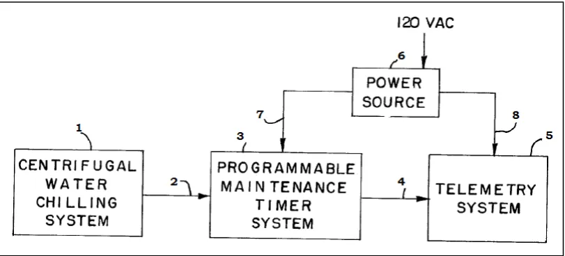
Figure 2.1 shows an overall block diagram of a programmable maintenance timer system of the present invention interconnected to a centrifugal water chilling system and a telemetry system. This programmable maintenance timer system is generally designed by reference numeral 3 and receives an input signal from centrifugal water chilling system 1 and line 2. An output signal is then generated on line 4 for delivering it to a telemetry system 5. A power source 6 has its output applied to the timer system via the line 7 and to the telemetry system 5 via line 8. Its input is 120 VAC.
Figure 2.1: Overall block diagram of a programmable maintenance timer system (John C. Hansen, Spring Grove, Lioyd A. Johnson, Dover, 1985)
10
Figure 2.2: A block diagram showing in more detail the power source 6 illustrated in Figure 2.1 (John C. Hansen, Spring Grove, Lioyd A. Johnson, Dover, 1985)
Scott R. Wheeler, Dominic Baulier (2010) invented a revolution counter for turning assemblies. This revolution counter generally relates to a tool and associated method for keeping accurate count of the number of turns that a driving part, example: a wrench is used to drive or turn a driven part such as a shaft or gear. Particularly, it is directed to a mechanical revolution counter for keeping track of the number of turns a driven part is driven for adjustment to a target or optimal position. A memory counter circuit maintains a count of turns and increments of the driven part by the driving part, and a reference setting circuit sets a reference setting of the memory counter circuit when a count is to be taken. The device body has a first portion mounting the adapter shaft with the rotary encoder, an intermediate housing containing the memory counter circuit, and a second portion at a distance from the first portion and of a sufficient mass that acts to orient the device body to a gravity-determined position as a reference position. The memory counter circuit receives output signals from the rotary encoder circuit and maintains a count relative to a reference position of the device body.
11
Figure 2.3: Diagram of a preferred embodiment of a Revolution Counter Tool (Scott R. Wheeler, Dominic Baulier, 2010)
12
Figure 2.4: Isometric view of the Tool width counter components in its housing (Scott R. Wheeler, Dominic Baulier, 2010)
2.2 Predictive Maintenance