AUTOMATIC SATELLITE SIGNAL TRACKING SYSTEM
MOHAMMAD AIZAD BIN MOHAMMAD IDRIS
This report is submitted in partial fulfillment of the requirements for the award of Bachelor of Electronic Engineering (Telecommunication Electronics) with Honours
Faculty of Electronic and Computer Engineering Universiti Teknikal Malaysia Melaka
UNIVERSTI TEKNIKAL M ALAYSIA M ELAKA
FAKULTI KEJURUTERAAN ELEKTRONIK DAN KEJURUTERAAN KOM PUTER
BORANG PENGESAHAN STATUS LAPORAN
PROJEK SARJANA M UDA II
Tajuk Projek : AUTOM ATIC SATELLITE SIGNAL TRACKING SYSTEM
Sesi Pengajian : 2008/ 2009
Saya MOHAMMAD AIZAD BIN MOHAMMAD IDRIS
mengaku membenarkan Laporan Projek Sarjana Muda ini disimpan di Perpustakaan dengan syarat-syarat kegunaan seperti berikut:
1. Laporan adalah hakmilik Universit i Teknikal M alaysia M elaka.
2. Perpust akaan dibenarkan membuat salinan unt uk t ujuan pengajian sahaja.
3. Perpust akaan dibenarkan membuat salinan laporan ini sebagai bahan pert ukaran ant ara inst it usi
pengajian t inggi.
4. Sila t andakan ( √ ) :
SULIT*
(M engandungi maklumat yang berdarjah keselamat an at au kepent ingan M alaysia sepert i yang t ermakt ub di dalam AKTA RAHSIA RASM I 1972)
TERHAD* (M engandungi maklumat t erhad yang t elah dit ent ukan oleh organisasi/ badan di mana penyelidikan dijalankan)
TIDAK TERHAD
Disahkan oleh:
__________________________ ___________________________________
iii
“I hereby declare that this report is the result of my own work except for quotes as cited in the references”
Signature : ………..
iv
“I hereby declare that I have read this report and in my opinion this report is sufficient in terms of the scope and quality for the award of Bachelor of Electronic Engineering
(Telecommunication Electronics) with Honours”
Signature : ……….. Supervisor’s Name : ABDUL RANI BIN OTHMAN Date : ………..
v
vi
ACKNOWLEDGEMENT
First and foremost, I would like to give thanks to ALLAH SWT for helping me through all the obstacles that I encountered during the work of this project.
I would like to express my appreciation to my supervisor, Abdul Rani Bin Othman for his support and guidance throughout this whole project.
I would like to thank my beloved family and my relatives for their encouragement and never ending support. Their support and lovely companionship is another important source of strength for me. My deepest appreciation goes to all my friends for the fruitful suggestion, proof reading and wishes.
vii
ABSTRACT
viii
ABSTRAK
ix
TABLE OF CONTENT
CHAPTER TITLE PAGE
`
PROJECT TITLE i
ABSTRAK ii
ABSTRACT iii
TABLE OF CONTENT iv
LIST OF TABLES v
LIST OF FIGURES vi
I INTRODUCTION 1
1.1 Project Introduction 1
1.2 Project Objective 3
1.3 The Scope of Work 3
1.5 Methodology 4
II LITERATURE REVIEW 5
2.1 Satellite Dishes 5
2.1.1 Parabolic 7
x
2.1.3 Cass 7
2.1.4 Principle of Operation 8
2.2 Low Noise Block Converter 10
2.3 Comparator 12
2.3.1 Types of Comparator 12
2.3.1.1 Inverting and Noninverting Comparator 12
2.3.1.2 Comparator with Hysteresis 13
2.3.1.3 Voltage comparator (using Op-amp) 15 2.3.1.4 Microvolt comparator 17
2.4 Comparison between Comparator 18
2.5 Motorized Satellite Dish 20
2.5.1 Rotation of Stepper Motor 21
2.6 Frequency to Voltage Converter 23
2.6.1 Types of Converter 23
2.6.1.1 LM2917 - Frequency to Voltage Converter 23
2.6.1.2 VFC320 - Frequency to Voltage Converter 26
2.6.1.3 LM331A/LM331 Precision Frequency to Voltage Converters 28
xi
III PROJECT METHODOLOGY 32
3.1 Introduction 32
3.2 Flow Chart 33
3.3 Signal Tracking System Model 34 3.4 Measured Amplified Signal 34 3.5 Power Supply System and Circuit 36 3.6 Comparator F/V Circuit 36
IV RESULT AND DISCUSSION 38
4.1 Comparator Circuit 38
4.1.1 Work out with Function Generator 39
4.1.2 Troubleshooting 40
4.2 Block Diagram of System 43
4.3 Automatic Satellite Signal Tracking System 43
V CONCLUSION AND SUGGESTION 45
5.1 Conclusion 46
5.2 Suggestion 46
xii
LIST OF FIGURES
NO TITLE PAGE
1.0 Block Diagram of Home Terminal Reception 2 2.1 Types of dishes (a) Parabolic, (b) Off-center, (c) Cassegrain 6 2.2 (1) C-band dishes, (2) Ku-band dishes 9
2.3 Low Noise Block Converter 10
2.4 LNB Illustration Diagram 11
2.5 Non-inverting Comparator 13
2.6 Inverting Comparator 13
2.7 Inverting comparator with Hysteresis 14 2.8 Non-inverting comparator with hysteresis 14 2.9 Schematic Diagram of voltage comparator 16
2.10 Illustrated of circuit 16
2.11 Schematic diagram of microvolt comparator 18
2.12 Rotations of motor 22
xiii
2.14 Connection Diagram of Converter (8-pin) 24 2.15 Connection Diagram of Converter (14-pin) 25
2.16 Functional Block Diagram 27
2.17 Connection Diagram for F/V Conversion 27
2.18 Functional Block Diagram 29
2.19 Frequency-to-Voltage Converter 29 3.1 Model of Tracking System 34 3.2 Amplifier Circuit Diagram 35 3.3 Regulated DC Diagram 36
3.4 F/V circuit 37
4.1 Comparator Circuit 38
4.2 Tested with Function Generator 39
4.3 Troubleshooting with Yagi Antenna 40
4.4 Block Diagram of System 43
4.5 Tracking System Model 43
xiv
LIST OF TABLES
NO TITLE PAGE
2.1 Typical overdrive delay 17
2.2 Comparison of LM360 and uA760C 19
2.3 Comparison of LM261 and NE529 19
xv
LIST OF GRAPH
NO TITLE PAGE
CHAPTER 1
INTRODUCTION
1.1 INTRODUCTION
The use of satellite in communication systems is very much a fact of everyday life, as is evidenced by the many homes which are equipped with antennas or dishes used for reception of satellite television. Satellite form an essential part of telecommunication systems worldwide, carrying large amounts of data and telephone traffic of data in addition to television signals.[1]
2
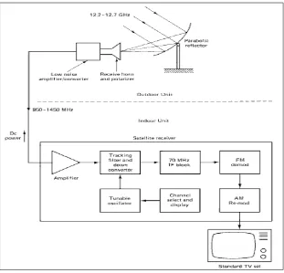
Figure 1.0 Block Diagram of Home Terminal Reception
Figure 1.0 shows the communication between outdoor unit and indoor unit. Outdoor unit consist the antenna types, horn receiver and low noise amplifier/converter. The signal on the antenna will be transmit to indoor unit consist satellite receiver and output device (television).
3
1.2 PROJECT OBJECTIVE
The objective of my project is to develop a model of Automatic Satellite Signal Tracking System.
1.3 SCOPE OF WORK
After identified the scope of work needed, there are several main areas that have to be done:
1. Literature Review
These consist of existing research done about satellite system prediction and design model.
2. Suitable data for design
The system design will consider the suitable parameter in order to determine the model
3. Prototype model
Since all the parameters and component of circuits were gathered, next is to predict the model.
4. Performance testing
After constructed the circuit for the system, the circuit are need to test the effectiveness and maintain the results
5. Model of system
4
1.4 PROJECT METHODOLOGY
This project started by studying the basic fundamental of satellite communications. All of this information was obtained from journal, paper, book and sites.
There are many types of tracking system designed in the market today, but several of them are operated in manual way. By improving the existed design, the system will able to operate automatically. The signal tracked on the antenna/dishes usually comes from many different angles before it can store into receiver panel. The problem is, the rotation of antenna/dishes only can rotate in 2 ways either horizontal or vertically. After some considerations, the system will operate the antenna/dishes on horizontal ways which give more area of searching to antenna/dishes.
Besides attenuation effects, the strength of signal coming into antenna/dish also need to be considered. The signal captured on the antenna must be strong enough to trigger the comparator circuit. Means, the antenna wouldn’t stop rotating if signals are not strong /sufficient.
It’s very important for antenna to rotate smooth and slow enough to capture the signal. These motors must capable to rotate 360 degree forward and backward since several wires will attach to motor’s body. If not, wires might be twisted around and spoils the VHF and UHF plates.
CHAPTER 2
LITERATURE REVIEW
2.1 SATELLITE DISHES
6
(a) (b)
[image:21.612.141.515.97.541.2](c)
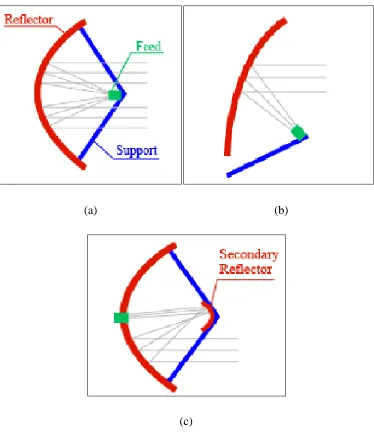
Figure 2.1 Types of dishes (a) Parabolic, (b) Off-center, (c) Cass
7
2.1.1 Parabolic
There are a number of dish antenna types. The first and simplest is the Prime Feed Focus dish, which is a parabolic dish with the LNC mounted centrally at the focus. Because the LNC is mounted centrally, it means that a lot of the incoming signals are blocked by the LNC. Its efficiency of 50% is low compared with the other types. The Prime Feed Focus dishes are mainly used for antennae with diameters over 1.4 meters. The parabolic antenna is less sensitive to small directional deviations and there is a better chance of receiving signals outside the normal footprint. On the other hand, rain and snow can easily collect in the dish and could interfere with the signal.[3]
2.1.2 Off Dish
The Offset Dish Antenna has its LNC not mounted centrally, but to the side of the dish. Because the LNC no longer obstructs the signal path, the dish has a better performance than the Prime Feed Focus dish. This allows the dish diameter to be smaller. Another advantage of this type of dish is that it can be positioned almost vertically, whereas the Prime Feed Focus dish needs to be positioned more obliquely. The problem that it could collect rain and snow and give disturbance to the signals is therefore less likely to happen.[3]
2.1.3 Cass
8
2.1.4 Principle of operation
The parabolic or any shape of a dish reflects the signal to the dish’s focal point. Mounted on brackets at the dish's focal point is a device called a feedhorn. This feedhorn is essentially the front-end of a waveguide that gathers the signals at or near the focal point and 'conducts' those to a low-noise block downconverter or LNB (Figure 2.03). The LNB converts the signals from electromagnetic or radio waves to electrical signals and shifts the signals from the downlinked C-band and/or Ku-band to the L-band range. Direct broadcast satellite dishes use an LNBF, which integrates the feedhorn with the LNB. (A new form of unidirectional satellite antenna, which does not use a directed parabolic dish and can be used on a mobile platform such as a vehicle).[4]
9
(1) (2)
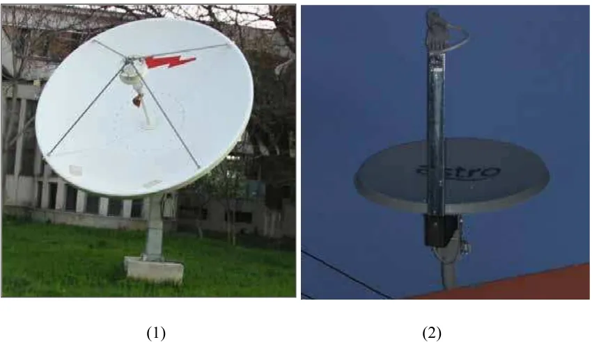
Figure 2.2 (1) C-band dishes, (2) Ku-band dishes
[image:24.612.116.541.69.315.2]