UNIVERSITI TEKNIKAL MALAYSIA MELAKA
PARAMETER SELECTION FOR MACHINING VARIOUS
TYPE OF MATERIAL IN MILLING MACHINE
This report submitted in accordance with requirement of the Universiti Teknikal Malaysia Melaka (UTeM) for the Bachelor of Manufacturing Engineering
Technology (Product Design) with Honours
by
SURAYA BT SAAD B071210413 880218-02-5410
UNIVERSITI TEKNIKAL MALAYSIA MELAKA
BORANG PENGESAHAN STATUS LAPORAN PROJEK SARJANA MUDA
TAJUK: PARAMETER SELECTION FOR MACHINING VARIOUS TYPE OF
MATERIAL IN MILLING MACHINE
SESI PENGAJIAN: 2014/15 Semester 2
Saya SURAYA BT SAAD
mengaku membenarkan Laporan PSM ini disimpan di Perpustakaan Universiti Teknikal Malaysia Melaka (UTeM) dengan syarat-syarat kegunaan seperti berikut:
1. Laporan PSM adalah hak milik Universiti Teknikal Malaysia Melaka dan penulis. 2. Perpustakaan Universiti Teknikal Malaysia Melaka dibenarkan membuat salinan
untuk tujuan pengajian sahaja dengan izin penulis.
3. Perpustakaan dibenarkan membuat salinan laporan PSM ini sebagai bahan pertukaran antara institusi pengajian tinggi.
4. **Sila tandakan ( )
SULIT
TERHAD
TIDAK TERHAD
(Mengandungi maklumat yang berdarjah keselamatan atau kepentingan Malaysia sebagaimana yang termaktub dalam AKTA RAHSIA RASMI 1972)
(Mengandungi maklumat TERHAD yang telah ditentukan oleh organisasi/badan di mana penyelidikan dijalankan)
Alamat Tetap:
Kg Pida 14 Jln Sanglang,
06150 Ayer Hitam,
Kedah Darul Aman
Disahkan oleh:
Cop Rasmi:
iv
DECLARATION
I hereby, declared this report entitled “Parameter Selection for Machining Various Type of Material in Milling Machine” is the results of my own research except as cited in references.
Signature :………
Name : SURAYA BINTI SAAD
v
APPROVAL
This report is submitted to the Faculty of Engineering Technology of UTeM as a partial fulfillment of the requirements for the degree of Bachelor of Engineering Technology (Product Design). The member of the supervisory is as follow:
vi
ABSTRACT
vii
ABSTRAK
viii
DEDICATIONS
ix
ACKNOWLEDGMENTS
In the name of Allah, the most Gracious and most Compassionate
Praise to God for His help and guidance that I am able to complete the task of this Bachelor Degree Project. A special thanks to my supervisor, Mr. Abd Khahar Bin Nordin that had guided me throughout this study from the beginning until the end. Besides, his had given me invaluable advices that empower my spirit and passion toward the job and the tolerance of my silly mistakes. I would like to take this chance to thank his for the support and encouragement whenever I faced any problems while completing this study. I am very thankful for the time that his had been spent with me for the study and correcting my mistakes even though his had a busy working schedule.
Many thanks to all of the technicians in Manufacturing Technology Laboratory, Mr.Azimin, Mr. Hisyam and Mr. Fauzi for their cooperation and assisting me in the various laboratory tasks. I would like to express thank to all of my friend because helping directly or indirectly during the conducted my project. Without the help in terms of ideas from them, it sure is hard for me to complete my project.
x
LIST OF SYMBOLS AND ABBREVIATIONS ... xvi
xi
2.2 Computer Numerical Control (CNC) Machines ... 9
2.3 Milling Operation ... 12
2.3.1 Face milling ... 12
2.4 Milling Cutter and Insert ... 15
2.5 Cutting Parameter ... 16
2.6 Workpiece Properties ... 19
2.6.1 Aluminium ... 19
2.6.2 Mild Steel ... 20
2.7 Surface Roughness ... 20
2.7.1 Principal Elements of Surface ... 22
2.7.2 Surface Finish in Machining ... 23
2.8 Surface Roughness Tester ... 23
2.9 Surface Roughness Parameter ... 25
2.10 Analysis Of Variance (ANOVA) Software ... 26
2.11 Chip Formation ... 28
3.3.1 Aluminum Alloy 1100 ... 32
xii
3.4 Parameter Selection ... 34
3.5 Method of Machining ... 34
3.6 Apparatus ... 35
3.7 Preparation machine ... 36
3.8 Cutting Process ... 39
3.9 Labelling ... 39
3.10 Surface Roughness Tester ... 40
3.10.1 Surface Roughness Measurement ... 42
3.10.2 Surface Roughness Tester Calibration ... 42
3.10.3 Taking Surface Roughness Measurement ... 43
3.11 Data Analysis ... 43
CHAPTER 4 ... 44
4.0 Introduction ... 44
4.1 Findings Average of surface roughness ... 45
4.2 Data analysis for mild steel specimen ... 47
4.2.1 Analysis of Interaction Plot for mild steel ... 47
4.2.2 Analysis of Main Effect Plot for mild steel ... 49
4.2.3 Analysis of Variance ... 50
4.3 Data analysis for Aluminium specimen ... 51
4.3.1 Analysis of Interaction Plot ... 51
4.3.2 Analysis of Main Effect Plot for aluminium ... 52
4.3.3 Analysis of Variance for aluminium ... 54
xiii
4.6 Limitation of research and future work suggestion ... 59
CHAPTER 5 ... 60
5.0 Introduction ... 60
5.1 Conclusion ... 60
5.2 Recommendation ... 61
xiv
LIST OF FIGURES
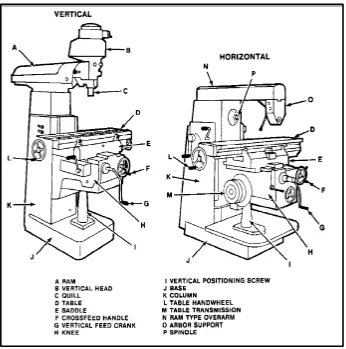
Figure 2.1: Type of milling machine ………... 9
Figure 2.2: Machine tool for CNC milling……….11
Figure 2.3.1 (a): Face Mill Operation……….12
Figure 2.3.1 (b): Face Mill Operation, showing action of an insert………....12
Figure 2.3.1 (c): Action of Climbing Milling………..13
Figure 2.3.1 (d): Action of Conventional Milling………13
Figure 2.3.1 (e): A face-milling cutter with index able insert……….14
Figure 2.4: Relative edge strength and tendency for chipping of insert with various shape. (The Goodheart-Willcox Co.)………..15
Figure 2.7: Fishbone diagram with influential factors on machined surface roughness ……….20
Figure 2.7.1: Roughness and waviness profile...21
Figure 2.8: Portable Surface Roughness SJ-410……….23
Figure 2.10(b): The interaction plot for surface roughness……….26
Figure 2.10(c): The main effects plot of surface roughness………....26
Figure 2.11: Types of chip formation………28
Figure 3.1: Flow chart as a guild project………...30
Figure 3.2: Material preparation for specimen………31
Figure 3.9: Labelling on specimen………...39
Figure 3.9: Surface roughness tester SJ-410………...39
Figure 4.2.1: Graph interaction plot for surface roughness………...46
Figure 4.2.2: Graph main effect plot for surface roughness………...48
Figure 4.3.1: Graph interaction plot for surface roughness………..50
Figure 4.3.2: Graph main effect plot for surface roughness………...51
Figure 4.4(a): Chip formation for mild steel specimen………...54
xv
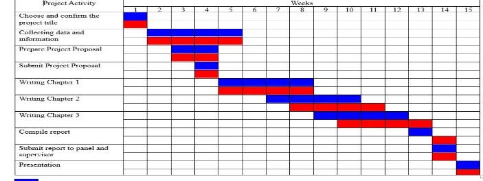
Table 1.6: Gantt chart for PSM 1……….5
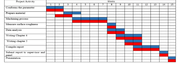
Table 1.6: Gantt chart for PSM 2……….6
Table 2.5 (a): Cutting parameter in milling process………...15
Table 2.5 (b): Cutting speed for different material………..17
Table 2.5 (c): Recommendation of cutting speed and feed rate………..17
Table 2.5 (d): Recomendation cutting parameters for aluminum……….18
Table 2.5 (e): Recomendation cutting parameters for plain carbon steel……….18
Table 2.7.1: Definition of surface structure……….21
Table 2.10(a): Table of analysis of ANOVA………..25
Table 3.3.1 (a): Chemical composition of Aluminum 1100 alloy………31
Table 3.3.1 (b): Mechanical properties of Aluminum 1100 alloy………32
Table 3.3.2(a): Chemical composition of AISI 1018 carbon steel………..32
Table 3.3.2(b): Mechanical Properties of AISI 1018 carbon steel………...32
Table 3.4: Parameter selection for machining process……….33
Table 3.6: Apparatus for machining process………..34
Table 3.9(a): Specification of SJ-401………..40
Table 3.9(b): Features of SJ-410………...40
Table 4.1 (a): The overall data of average roughness value for mild steel…………..44
Table 4.1 (b): Detail result data for mild steel specimen………..44
Table 4.1 (c): The overall data of average roughness value for Aluminium………….45
Table 4.1 (d): Detail result data for aluminium specimen………45
Table 4.2: Result of average roughness value for mild steel………...46
Table 4.2.3: ANOVA table for response function of the surface roughness………….49
Table 4.3: Result of average roughness value for aluminium………50
Table 4.3: Result of average roughness value for aluminium……….53
xvi
LIST OF SYMBOLS AND ABBREVIATIONS
AA = Arithmetic Average
AL = Aluminium
ANOVA = Analysis of Variance
ANSI = American National Standard Institute CLA = Center Line Average
CNC = Computer Numerical Control
Cu = Copper
DIN = German National Standard F-test = Fisher Test
HSS = High Speed Steel ISO = International Standard
JIS = Japanese Industrial Standards
mm = Millimetre
QC = Quality Control Ra = Average Roughness Rev/min = Revolution per Minute Rp = Smoothing Depth
RPM = Millimeter per Revolution Rq = Root mean square
SFM = Surface feet per minute TiNC = Titanium Carbide
1
CHAPTER 1
INTRODUCTION
1.0 Introduction
Surface finish is a surface texture also knows as characteristics of surface. The quality of surface finish is very important because is able to effect the quality of product. Thus, selection correct machining parameters are able to produce high quality of surface finish when machined workpiece. Cutting parameters like cutting speed, spindle speed, feed rate, and depth of cut is important in material remover. Surface roughness influences some functions of work piece like contact causing surface friction, fatigue resistance, wearing, heat transmission, and coating (Daud, Ng, Sivakumar and Selamat, 2015). According to Suleiman, Usman and Apasi (2011), cutting parameter selected based on the workpiece material, cutting tool material and tool size will be used. This project is analysis the effect of cutting parameters like cutting speed, feed rate, and depth of cut on surface roughness for different type of material using CNC milling machine. This chapter will explain about project from introduction, objectives, problems statement, project scope and project outline.
1.1 Background
2
Two different type of material is used for doing this project, it is Aluminum 1100 alloy and Mild Steel AISI 1018. The flat shape of material is selected and machining in form of flat surface. The cutter and the path of that cutter used to evacuate material from the work piece is the face milling operation. The correct cutter material is very important to tool life in order to avoid tool wear. Cutting tool material to machining the remover surface is carbide insert. After milling process, surface roughness value were measured using a portable surface roughness SJ-410. The result of surface roughness were analyses using the Minitab software. Minitab software was performed to identify the effect of cutting the effect of cutting parameters on surface finish.
This parameter will be studied and do the machining to produce data that can used as references to new user that want to learn the milling process. These parameter will used as guidelines to machinist in selecting the correct parameter of cutting tool to the type of material being cut.
1.2 Problem Statement
3 The objective of this project are:
i. To study the effect of cutting parameter such as cutting speed, depth of cut and feed rate on surface roughness for milling operation.
ii. To finding the correct cutting parameter to the type of material being cut. iii. To analyses the result of cutting parameter for materials used.
iv. To produce sample, recommendation and references for new comes student in machining technology (milling).
1.4 Scope of Study
4
1.5 Project Outline
The parameter selection for machining various type of material in milling machine for PSM project is a combination of 5 chapters overall that contains and explain the topics such as the introduction, literature review, methodology, result and discussion, and lastly conclusion and recommendation.
Chapter 1: Introduction of the project. This chapter will concentrate about the project and objectives of the project will be elaborated. It is followed by the explanation of scope project, problem statements and project outline.
Chapter 2: This chapter will concentrate about the literature review. This chapter will be explain with some of basic information about the milling machine and CNC milling machine. Next, the surface roughness is reviewed together with milling cutting parameter and cutting tool that play an important role in determining the surface roughness material. Some literature reviews of current existing projects based on effect of cutting parameter on surface finish are also be discussed.
Chapter 3: Methodology of the project. This chapter is consists of the procedure that is used to conduct the whole research experiment from the beginning until the end of project.
Chapter 4: Result and Discussion. The results obtained from this experiment will be discussed. A graphs will be represent to shows the relationship between the parameters and surface roughness it produced by different machining parameters like cutting speed, feed rate and depth of cut. The factor that effect the result obtained will be discussed.
5
1.6 Planning Project
6 Table 1.6(b): Gantt chart for PSM 1
7
CHAPTER 2
LITERATURE REVIEW
2.0 Introduction
8
2.1 Milling Machine
Milling machine is most versatile and useful machine tools because they are able performing a variety type of cutting operations. First milling machines was built in 1820 by Eli Whitney (1765 to 1825). Now, many selection of milling machines with various features are available. Kalpakjian and Schmid (2010) state the numerous machines and operations are now being with computer control and machining centre. But, manually controlled machines it is still widely used, particularly for small production run because it’s cheap.
According to Joshua, David and Ismail (2015) milling is one of the common removing processes or metal cutting. It is a process that of generating machined surfaces with progressively removing a predetermined total of material or stock from the work piece at a relatively slow rate of movement or feed with a milling cutter rotating at a rather high speed. One other word, Bawa (2004) state the milling is a material remover process, that is used for machining curve, flat, and irregular surfaces by feeding the work piece against a rotating cutter that contain several cutting edges. Axis of rotation the cutting tool perpendicular to the direction of feed, whether perpendicular or parallel to machined surface. There are various types of milling machines available in the market and has its own characteristics.
9
computer numerical control (CNC) machines. This machine are versatile and are capable of milling, drilling and boring with repetitive accuracy. For this project, the CNC vertical milling machine was used to machining the surface roughness.
Figure 2.1: Type of milling machine
2.2 Computer Numerical Control (CNC) Machines