Identification and Simulation of Dc-Dc Boost Converter for Charging Up PV
Voltage for 24-Volts Battery
Aziah Khamis*1, M.Nizam Kamarudin*2, Musa Yusup Lada*2, Mohd Saifuzam Jamri*2, F. Hanafi*1 and A. Nazmi*1
This manuscript is a piece of report on the identification of a DC-DC Boost switched mode converter for charging up Photovoltaic (PV) voltage for 24-volts battery. A DC-DC Boost converter with unknown mathematical characteristic is identified using Auto-Regressive with Exogenous Input (ARX) model. The identification of such DC-DC converter, on the basis of recorded data from PV is conducted to obtain the mathematical model of the converter. The knowledge about the converter is then beneficial for the design process of a PV’s maximum power point tracking (MPPT) system. The identification process that exploits the advantage of linear parametric ARX gives beneficial information such as correlation, best fit and poles-zeros location. The purpose of identification is to obtain the best model of the converter and hence, beneficial the simulation and controller design phase which include the MPPT.
Keywords: maximum power point tracker (MPPT), Boost converter, P&O alghorithm
1. Introduction
Photovoltaic (PV) generation offers many advantages in producing renewable source of energy as it incurring no fuel costs, not being polluting, requiring less mainte-nance and emitting no noise compared to its counterpart [1]. DC-DC Boost converter is used to magnify the voltage from PV to a suitable form of energy accepted by the load. Boost converter’s brain will be the Maxi-mum Power Point Tracker (MPPT) in which it tries to stabilize the voltage produced by the boost converter through its intelligently controlled algorithm. Boost converter is a second order system [2] consists of an inductor, a capacitor, a diode, and with the load resis-tance connected in parallel with the capacitor. The use of DC-DC boost converter in boosting up PV output voltage is essential for charging up 24-volts battery. As the output from PV is not constant due to the ambient temperature and environmental condition, the modelling of such converter is crucial to ensure regular charging up of the battery. This paper however, focuses on the modelling and identification of DC-DC boost converter based on the output voltage produced by the photo-voltaic module. A DC-DC boost converter can be modelled based on the knowledge about PV voltage as well as a calculated duty cycle for MPPT.
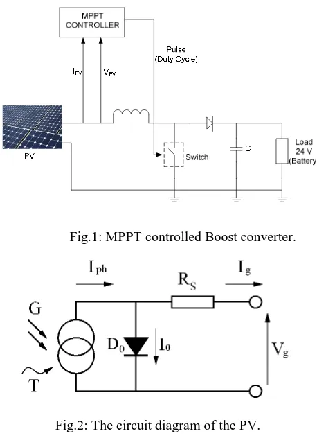
MPPT systems are used mainly in systems where source of power is nonlinear such as the solar PV modules. In this work, MPPT integrated boost converter system is used in solar PV applications with a battery charger connected stand-alone PV system. The purpose of charging a battery (lead acid/NiCad) is nothing but for the storage of electrical energy. This energy if it comes from the solar PV systems then fast charging of the battery can be done with the help of the MPPT-boost converter charge controller. The good controller is expected to be designed. As such, the MPPT and boost converter need to be identified beforehand. Fig.1 shows the overall system configuration whereas Fig.2 indicates a typical PV circuit diagram. Note that in Fig.2, the current source proportional to the light falling on the cell in parallel with a diode D0. Iph is the temperature dependence of the photo-generated current. I0 is the temperature dependence of the reverse saturation current of the diode D0. A series resistance (Rs) gives a more accurate shape between the maximum power point and the open circuit voltage.
_______________________
Correspondence: 1,2Faculty of Electrical Engineering, Universiti Teknikal Malaysia Melaka, Durian Tunggal, 76109 Melaka, Malaysia
Phone: +606-5552256, Fax: +606-5552222, Email: [email protected]
Fig.1: MPPT controlled Boost converter.
Fig.2: The circuit diagram of the PV.
2. Modeling and Simulation
2.1 The Converter
DC-DC converters are dynamical systems with highly nonlinear behavior. The use of semiconductor devices as a switch makes the system non-linear. Moreover, the parasitic capacitances and inductances of the switches produce nonlinear phenomena of the converter built up by these power electronic components. Another source of nonlinear phenomena comes from the control circuits comprise of comparators, PWM generators, phase-locked loops, timers and digital controllers [3]. In DC-DC converters, load fluctuation behaves as disturbances to the system. As such, the system is non-linear in nature and cannot be easily solved analytically using Laplace transform. Therefore, the utilization of power-ful computer aided design package is required. Simulink from Mathwork is known as one of the tool used for modeling and controller design [4]. Author in paper [5] exploit state-space averaging model of the converter while modeling and designing the converter. In this paper, a mathematical model of DC-DC converters is obtained by performing system identification process. System identification process offers less complex mathematical derivation and worthwhile for controller design phase. The general model identification process
is shown in Fig.3 [6]. Through system identification process, all important information such as best fit, residual analysis, correlation, and pole-zero location are obtained. As such, the mathematical model and esti-mated model of DC-DC converter is acquired. From the identification knowledge, a controller and estimator of such DC-DC converter is designed easily. As DC-DC converters suffer from chaotic behavior and bifurcation phenomena, the use of identification tool in MATLAB is beneficial. As paper [7] presents a study of the chaotic behavior of the buck converter by simulating the buck converter in PSCAD/EMTDC, this paper however use MATLAB due to pre-defined advantages such as easily to observe transient behavior and assessable user friend-ly built in tool in it. The aim of identification process is nothing but to obtain the mathematical representation of such converter and hence, good controller as well as good estimator is to be designed.
Fig.3: DC-DC converter identification process.
A few structures of parametric model such as ARX model, Auto-Regressive Moving Average with Exogen-ous Input (ARMAX) model, output-error (OE) model and Box-Jenkins (BJ) model can be used as MPPT integrated Boost converter model structure. ARX model serves the basic structure as this structure ignores the moving average or the error dynamics of the system. As such, ARX model is used and the general model with appearance of error dynamics e(k) is represented by the difference equation (1). Lowercase ‘d’ is time delay which represent the difference between u(k) and y(k). The general ARX model is shown in Fig.4.
(1) e(k)
d) )u(k B(Z )y(k)
A(Z
−
1
=−
1
− + DC-DCconverter
Adjustable
Discrete-Time
Model
Parameter
Adaptation
Algorithm UK
YK
K K
Estimated model
Fig.4: ARX Model Structure.
2.2 Identification Process
The experimental PV output voltage is shown in Fig.5. The PV module is tested and the outputs of voltage are taken starting from 9.00a.m until 6.00p.m for three days continuously. It was taken using 50W PV of Conergy Solar India.
Fig.5: Recorded PV Voltage.
The PV produced nearly constant voltage with small fluctuation occurred. However, good parameters identi-fication requires the usage of input signal that are rich in frequencies. As such, the sinusoidal signals with DC offset which shown in the equation (2) is introduced.
(2) k t cos u(k) s 1 dc+∑
= =
p
i i i
a
V
ω
The Pseudo-Random Binary Sequences (PRBS) that generating the sequence of square pulses that modulated by different width can also be used. However, this method is bit difficult to be implemented as compared to the first one [6]. In equation (2), ai is amplitude; ωi is frequency and ts for sampling time. Note that P is determined by the number of buck converter parameter,
n that needs to be identified.
2.3 Dc-Dc Converter Model
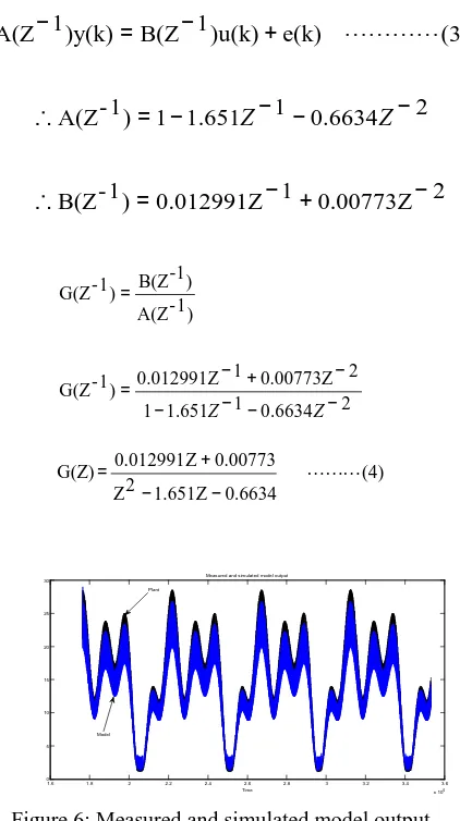
The set of input-output data is evaluated and esti-mated by the identification tool of SIMULINK / MATLAB. The relationship of a measured and simu-lated input-output data is shown in Fig.6. The converter model output yields 82.89 best fit. Fig.7 shows the plot of frequency response for the identified converter system. By examining the plot, it is acceptable that the converter is the best model of the identification process, plus it is stable in nature. However, the plot shows that the stability need to be improved as the phase plot has not meet the required -180° when the magnitude plot intersect 0dB line. The previous Fig.4 depicts the structure of ARX model in which the identification process of converter system took place.
The identification tool in MATLAB generates dis-crete time polynomial shown in equation (3). As ARX model ignore error dynamic of the converter or plant, equation (4) can be simplified further. Equation (4) provides information on the mathematical model of the converter system in discrete time domain.
2
0.00773Z
1
0.012991Z
)
1
-B(Z
2
6634
.
0
1
651
.
1
1
)
1
-A(Z
)
(3
e(k)
)u(k)
1
B(Z
)y(k)
1
A(Z
−
+
−
=
∴
−
−
−
−
=
∴
+
−
=
−
Z
Z
2 6634 . 0 1 651 . 1 1 2 0.00773Z 1 0.012991Z ) 1 -G(Z ) 1 -A(Z ) -1 B(Z ) 1 -G(Z − − − − − + − = = Z Z (4) 0.6634 Z 1.651 2 Z 0.00773 Z 0.012991 G(Z) − − + =1.6 1.8 2 2.2 2.4 2.6 2.8 3 3.2 3.4 3.6 x 10⁶ 0 5 10 15 20 25 30 Time Measured and simulated model output Plant
Model
Figure 6: Measured and simulated model output yields best fit of 86.93
u(k) y(k)
e(k)
+ +
Start
Read V(k) & I(k) From panel
Calculate P(k)=V(k)*I(k)
Delay P(k)&V(k) by k-1 instant P(k-1),V(k-1)
P=P(k)-P(k-1) V=V(k)-V(k-1)
∆ ∆
P>0
∆
V<0 V<0
∆ ∆
D=D+ D∆ D=D- D∆ D=D- D∆ D=D+ D∆
To switch
Y N
Y N Y N
10-3 10-2 10-1 100 101 10-2
100
A
m
p
li
tu
d
e
Frequency response
10-3 10-2 10-1 100 101 -250
-200 -150 -100 -50 0
Frequency (rad/s)
P
h
a
s
e
(
d
e
g
)
Figure 7: Frequency response
3. Result and Discussion
3.1 MPPT Design and Controller Tuning
Upon completion of identification process, the con-troller can be designed easily. The amount of power generated by the PV is highly depends on the operating point of the PV array where the maximum power point (MPP) varies with solar insulation and temperature. For that reason, PV modules still have relatively low con-version efficiency. As such, controlling MPPT is a must in a PV system. As the PV operates at its highest effi-ciency at the MPP, many methods have been developed by several researchers to track MPP and hence design the MPPT. For instance; in paper [8], the authors utilize the look-up table on a microcomputer to track MPP. Whereas in paper [9], the authors apply a dynamic MPP tracker to PV supported appliances. Some researchers develop an intelligence control methods such as fuzzy logic [10, 11] and artificial neural network to track MPP as well as in MPPT design method. In most of the research, a question arises on how vary the duty cycle and in which direction so that peak power is reached. Researchers proposed an automatic tracking by exploit-ing various algorithm such as Perturb and Observe (P&O) [5, 12], Incremental Conductance [13, 14], Parasitic Capacitance [14], Voltage Based Peak Power Tracking [14] and Current Based peak power Tracking [14].
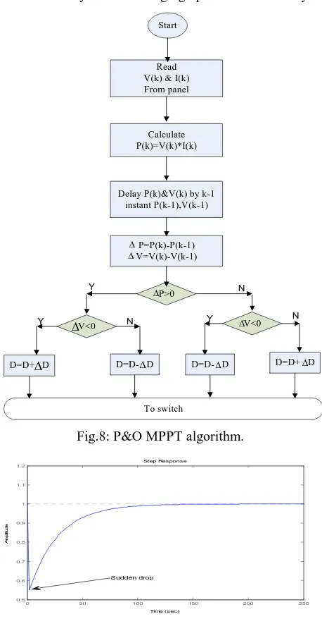
In this work, P&O method is used and being opti-mized with PID compensator. P&O MPPT algorithm is shown inFig.8 [5]. The algorithm start by reading and processing the PV output voltage V(k) and current I(k). The generated power P(k) is then computed and processed further. PID is the best-known controller in industries. This scheme offers simple structure as well
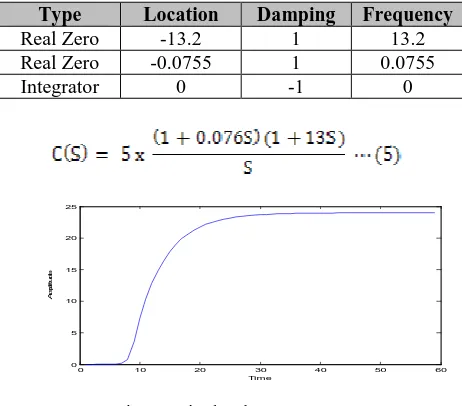
as robust performance. In the design process, further increase of Kp will result in the closed loop system becoming unstable. Therefore, additional integral is to improve steady state accuracy without introducing instability. Integrator gives the system one pole at origin, hence reducing steady state error as a steady-state error of a system depends upon the number of poles at the origin of the closed loop characteristic function [15]. The tuning of PID parameters called Kp, Ki and Kd for the MPPT optimization are based on Open Loop Zigler-Nichols tuning algorithm. The dynamics of PID is tabulated in Table 1. The compensator is represented in equation (5). Fig.9 depicts the output of the DC-DC boost converter without MPPT attached to it. Whereas Fig.10 represents the output of the MPPT-plus-Compensator equipped DC-DC boost converter of the PV solar system for charging up a 24-Volts battery.
Fig.8: P&O MPPT algorithm.
Fig.9: Sudden drop in PV output without MPPT and Compensator.
Step Response
Time (sec)
A
m
p
lit
u
d
e
0 50 100 150 200 250
0.5 0.6 0.7 0.8 0.9 1 1.1 1.2
Table 1: Dynamics of PID Compensator for MPPT
Type Location Damping Frequency
Real Zero -13.2 1 13.2
Real Zero -0.0755 1 0.0755
Integrator 0 -1 0
0 10 20 30 40 50 60
0 5 10 15 20 25
A
m
p
lit
u
d
e
Time
Fig.10: Final voltage output
4. Conclusion
The identification of Dc-Dc converter using P&O algorithm method and by optimization of PID compen-sator can be design using MATLAB simulation. This would give the output of converter model yields at 82.89 best fit. Besides, it is acceptable that the converter is the best model of the identification process, plus it is stable in nature.
Acknowledgment
This research is supported by the Universiti Teknikal Malaysia Melaka (UTeM) through short term research grant. Authors are greatly indebted to UTeM manage-ment and Ministry of Higher Learning Malaysia.
References
[1]. Joe-Air Jiang, Tsong-Liang Huang, Ying-Tung Hsiao and
Chia-Hong Chen, “Maximum power Tracking for Photovoltaic Power
Systems”, in Tamkang Journal of Science and Engineering, Vol.
8, No 2, pp. 147-153, 2005.
[2]. William C. Y. Chan and Chi K. Tse, “Study of Bifurcations in
Current-Programmed DC/DC Boost Converters: From Quasi-
Periodicity to Period-Doubling”, in IEEE transactions on circuits
and systems—I: fundamental theory and applications, vol. 44,
no. 12, december 1997.
[3]. Jonathan H. B. Deane and David C. Hamill, “Instability,
Subharmonics, and Chaos in Power Electronic Systems”, IEEE
Transaction on Power Electronics. Vol 5. No. 3. July 1990.
[4]. M.Nizam.Kamarudin and Sahazati Md.Rozali, “Simulink
Implementation of Digital Cascade Control DC Motor Model - A
didactic approach”, 2nd IEEE International Conference on
Pow-er and EnPow-ergy (PECon 08), DecembPow-er 1-3, 2008, Johor Baharu,
Malaysia, pp:1043-1048.
[5]. Mohd Saifuzam Jamri and Tan Chee Wei, “Modeling and
Control of a Photovoltaic Energy System Using the State-Space
Averaging Technique” Energy Research Journal, ISSN:
1949-0151, Volume 01, 2009.
[6]. Mohd Nasir Taib, Ramli Adnan, Mohd Hezri Fazalul Rahiman,
“Practical System Identification”, Faculty of Electrical
Engineer-ing, UiTM 2007.
[7]. A. Mehrizi-Sani, W. Kinsner and S. Filizadeh, “On the Chaotic
Behaviour of Buck Converter”, Department of Electrical and
Computer Engineering, University of Manitoba Winnipeg,
Can-ada.
[8]. Ibrahim, H. E.-S. A. and Houssiny, F. F., “Microcomputer
Controlled Buck Regulator for Maximum Power Point Tracker
for DC Pumping System Operates from Photovoltaic System”,
Proceedings of the IEEE InternationalFuzzy Systems
Confe-rence, August 22_25, Vol. 1, pp. 406_411, 1999.
[9]. Midya, P., Kerin, P. T., Turnbull, R. J., Reppa, R. and Kimball,
J., “Dynamic Maximum Power Point Tracker for Photovoltaic
Applications”, Proceedings of the IEEE Power Electronics
Spe-cialists Conference, PESC, Vol. 2, pp. 1710_1716, 1996.
[10].Simoes, M. G., Franceschetti, N. N. and Friedhofer, M., “A
Fuzzy Logic Based Photovoltaic Peak Power Tracking
Control-ler”, Proceedings of the IEEE InternationalSymposium on
Indus-trial Electronics, pp. 300_325 (1998).
[11].Mahmoud, A. M. A., Mashaly, H. M., Kandil, S. A., Khashab,
H. E. and Nashed, M. N. F., “Fuzzy Logic Implementation for
Photovoltaic Maximum Power Tracking”, Proceedings of the
IEEE International Workshopon Robot and Human Interactive
Communication, Osaka, Japan, 27_29 (2000).
[12].B.K. Bose, P.M. Szczesny and R.L. Steigerwald,
“Microcompu-ter Control of a Residential Photovoltaic Power Conditioning
System”, IEEE Trans. On Industry Applications, vol. IA-21, no.
5, pp.1182-1191, Sep. 1985.
[13].K.H. Hussein et al, “Maximum Photovoltaic Power Tracking: An
Algorithm for rapidly changing atmospheric conditions”, Proc.
Inst. Elect. Eng. Vol. 142, pt. G, no. 1, pp. 59-64, Jan. 1995.
[14].D.P. Hohm, M. E. Ropp, “Comparative Study of Maximum
Power Point Tracking Algorithms using an Experimental,
Pro-grammable, Maximum Power Point Tracking Test Bed”, IEEE,
pp.1699-1702, IEEE.
[15].C.K. Lee and W.H. Pang, “Adaptive Control to Parameter
Variations in a DC Motor Control System Using Fuzzy Rules”, in
Second International Conference of Intelligent Systems, 1994,