Thick-Film Based Piezoelectric Material Lead
Zirconate Titanate (PZT) Performance Measurement
Using Berlincourt Method
*Swee-Leong Kok,
MIEEE,**Ahsan Qumrul,
**Siang-Yee Chang
*Faculty of Electronic and Computer Engineering, **Faculty of Manufacturing Engineering
Universiti Teknikal Malaysia Melaka,
Hang Tuah Jaya, 76100 Durian Tunggal, Melaka, Malaysia *[email protected]
Abstract— Lead Zirconate Titanate or PZT is a high performance piezoelectric material which is able to generate charges when a proportional amount of stress is applied on the material. It has the potential to be used to fabricate micro-power generator for powering low power electronic devices as well as smart structure to be function as sensors and actuators. One of the indicators for comparing the performance of the smart materials is the piezoelectric charge constant, d33. In this paper, the d33 of PZT fabricated in the form of thick-films were measured using Berlincourt Method whereby a standard dynamic force is applied to the materials and the resultant value of charges is recorded and compared over a period of time after the thick-films were polarized. The value is compared between clamped and unclamped samples which show a difference of about 45 % as a result of clamping effect. The experiment results also show that the thick-film PZT processed at 950 C and polarized at 220 V with a thickness of about 120 m has a piezoelectric charge constant of 82 pC/N.
Keywords — Lead Zirconate Titanate (PZT), Thick-Film, Berlincourt Method, piezoelectric charge constant, d33
I. INTRODUCTION
Naturally, some piezoelectric materials exist in the form of crystals like Quartz, Rochelle salt, and Tourmaline group minerals. However, to ease the process of fabricating miniature devices such as MEMS devices, artificial smart materials are desired in such a way that can be easily integrated with CMOS technology. There are a number of choices of smart piezoelectric materials such as polarized polycrystalline ceramics like barium titanium, lead zirconate titanate (PZT) and polymer piezoelectric materials like polyvinylidene fluoride (PVDF) and polyimide which can be manufactured [1].
Research and development in high performance piezoelectric ceramic had attracted great attention since the discovery of barium titanium oxide in 1940 [2]. This was followed by the discovery of lead titanate zirconate (PZT) in 1950s by Bernard Jaffe [3]. Compared to barium titanium oxide, PZT has a higher Curie point, higher total electric charge, and higher coercive voltage. PZT can be processed in bulk, thin-film, thick-film, and polymer forms in applications suited to their individual characteristics.
In this paper, PZT material in the form of thick-film ceramic [4] was being investigated for its piezoelectric charge constant, d33 which is generally acceptable constant for performance indication of different piezoelectric materials. Berlincourt method was used to measure the resultant charge generated by the piezoelectric material when a standard
dynamic force is applied on the materials. The value of the d33 is recorded and compared over a period of time after the thick-films were polarized.
Two series of samples were fabricated by co-firing at different profiles with peak temperatures of 850 °C and 950 °C were inspected. The measured electrical properties of an unclamped thick-film (free from adhering on substrate) was compared with clamped samples (firmly adhered on alumina substrate) to obtain accurate measurement as suggested by Torah et al [5] and Steinhausen et al [6].
II. PIEZOELECTRICITY
Piezoelectricity is the ability of certain crystals to generate a voltage when a corresponding mechanical stress is applied. The piezoelectric effect is reversible, where the shape of the piezoelectric crystals will deform proportional to externally applied voltage.
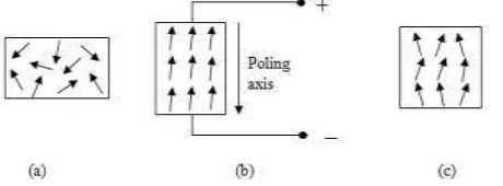
Fig. 1: Schematic diagram of the electrical domain: (a) before polarisation, (b) during polarisation and (c) after polarisation.
A piezoelectric crystal is built up by elementary cells consisted of electric dipoles, and dipoles near to each other tend to be aligned in regions called Weiss domains. These domains are randomly distributed within the material and produce a net polarisation as shown in Fig. 1 (a), therefore the crystal overall is electrically neutral.
III.BERLINCOURT MEASUREMENT METHOD
Generally there are two categories of piezoelectric material measurements methods: static and dynamic measurement methods. The static method is implemented by either directly applying force to the material and observing the charge generation or by applying constant electric field and observing the dimension change, while the dynamic method is using alternating electrical signal at high frequency to observe the frequency responses of the material [7].
Static piezoelectric measurement can be made by either direct or indirect methods. The direct method, also known as Berlincourt method, is conducted by applying a known force to a piezoelectric sample and the charge generated is measured as shown in Fig. 2.
Fig. 2: A photograph (a) and a schematic diagram (b) showing a piezoelectric specimen being measured with the Berlincourt measurement method.
The relationship between the generated charge and applied force is the piezoelectric charge coefficient as given in equation (1).
(1)
The subscripts i and j are the notations for poling direction and the applied stress direction respectively. A poled piezoelectric material produces a voltage of the same polarity as the poling direction for compressive force and on the other hand, voltage in the opposite direction is produced when tensile force is applied. This method is the simplest way to measure the d33 coefficient by using standard laboratory equipment.
Conventionally, thick-film piezoelectric materials are printed on a rigid substrate such as alumina and stainless steel. In this condition the film is rigidly clamped to the substrate which imposes a deformation restriction on the lower surface of the films when stress is applied as shown in Fig. 3.
Fig. 3: Diagram of a free-standing film in expansion (a) and contraction (b) compared to a clamped film in expansion (c) and contraction (d).
There are a few possible types of mechanical clamping for a film printed on a substrate [6]; one of which is where the piezoelectric film is mechanically bonded with an inactive substrate. With the presence of the substrate, an interfacial stress occurs between the printed piezoelectric film and the substrate and causes the measured effective piezoelectric coefficient d33 to reduce from the true value [5]. This is because of the influence of the d31 component in the film when a deformation of the structure occurs.
Theoretical analysis [5] shows that a reduction of measured d33 is inevitable for a clamped sample according to
(2)
Another problem associated with the determination of d33 is the fact that the system of substrate-piezoelectric film acts as a natural bending element. Therefore, to determine d33 correctly, the change in thickness of a specimen between two opposite points at the upper and the lower side of the sample must be measured [6].
IV.THICK-FILM LEAD ZIRCONATE TITANATE (PZT) FABRICATION PROCESSING
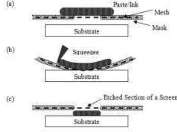
The first step in processing thick-film ceramic piezoelectric material is to formulate an optimum thick-film paste. The main ingredients for the pastes are PZT powder, high temperature permanent binder, low temperature temporary binder and solvent. These special formulised pastes using PZT as the functional material have been reported in [8]. The thick-film paste is then smeared across the pattern on the screen as shown in Fig. 4(a). A squeegee is then brought in contact with the screen with applied force, which deflects the screen (Fig. 4(b)) and the paste is drawn through by surface tension between the ink and substrate and deposits on the substrate under the screen which is rigidly held by the substrate holder as shown in Fig. 4(c).
Fig. 4: Thick-film screen printing steps.
binds the PZT particles together and later forms solid composite films once cooled down to a lower temperature. These films adhere firmly to the substrate. The presence of glass modifies the mechanical properties as well as the piezoelectric properties of the film. Therefore, it is important to mix PZT powder and glass frit in correct proportions. If the percentage of glass frit is more than necessary, hence reducing the PZT powder loading, then this will result in a lower piezoelectric activity. Polymer binders are also used as the permanent binder for fabricating flexible structures [9], which are generally cured at lower temperature (typically 100 – 200
C) with an infra-red dryer.
Temporary binders such as organic polymers together with solvents such as pine oil (or terpineol) are used to make thixotropic pastes, which can easily pass through the printing screen. They also serve to hold the paste together during the drying process, and are eventually evaporated off during the firing stage. Excessive solvent, however, will result in a smeared print and reduced definition of the printed geometry.
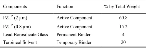
Table 1 shows the components of PZT paste formulation. Each of the components is expressed as a percentage of the total weight of the paste. Pz29 from Ferroperm Piezoceramics Ltd, which wass used in formulating the pastes. Two particle sizes of PZT were used; 2 µm and 0.8 µm, which made up 76 % of the total weight of the paste. 4 wt.% of lead borosilicate glass (Ferroperm CF 7575) was used as the permanent binder and 20 wt.% of terpineol solvent (ESL 400) was used as the temporary binder. All of the components were mixed together and homogenized with a triple roll mill.
The thickness that can be produced for PZT thick-films ranges from a few microns to hundreds of microns. The minimum film thickness is governed by the particle size of PZT, which is typically 0.8 – 2 m. There is no definite upper limit of thickness that can be produced, but films with thickness greater than 200 m is suitable to be fabricated with bulk piezoelectric materials for higher piezoelectric activity.
Table 1: PZT paste components.
Components Function % by Total Weight
PZT* (2 µm) Active Component 60.8
PZT* (0.8 µm) Active Component 15.2
Lead Borosilicate Glass Permanent Binder 4
Terpineol Solvent Temporary Binder 20
PZT* = PZT-5H or Pz 29
V. MEASUREMENT RESULTS AND DISCUSSION
By substituting the parameters for the properties of an alumina substrate and a clamped thick-film as listed in Table 2 into equation (2), the unclamped d33 can be estimated, which is slightly more than 80% compared to the measured value of a clamped sample.
The measured piezoelectric charge coefficient decayed as a continuously varying stress was applied to the materials. This is a common phenomenon for piezoelectric materials and arises because of several factors, including the presence of a defective interface layer, which can give rise to the backswitching of domains [10].
Table 2: Parameters for 96 % alumina substrate [5].
Parameter Value
Poisson ratio
Substrate dimensionless 0.25Young’s modulus
e
Substrate × 109 Pa 331Elastic compliance
s
11 E× 10-12 m2/N 16.4
s
12E × 10-12 m2/N -4.78
s
1E × 10-12 m2/N -8.45
A series of experiments were carried out to determine d33 for clamped and unclamped samples. A clamped sample is denoted for the thick-film piezoelectric material printed directly on an alumina substrate as shown in Fig. 5(a), while unclamped sample as shown in Fig. 5(b) is prepared by printing a layer of carbon sacrificial layer before the bottom electrode and the piezoelectric materials are printed as described in [11].
Fig. 5: Photographs of (a) a clamped sample printed across a score line on a substrate and (b) an unclamped sample held with a pair of tweezers.
The measurements were taken at two different periods of time; one of which was taken just after the samples had been polarised and the other was taken after six months following polarisation. Comparisons were also made on d33 with two different co-firing profiles, 850 °C and 950 °C.
Fig. 6 shows the d33 measurement results for the clamped sample at a continuous alternating mechanical force of 0.25 N at 110 Hz for 15 minutes at two conditions; one of which is taken just after polarisation and the other one is taken after six months from the first measurement. At the beginning of the measurement, a d33 value of 42 pC/N was measured which gradually dropped to 31 pC/N after 15 minutes. The second measurement was taken 6 months after polarisation. The initial value decreased to 32 pC/N and after 15 minutes of continuous application of alternating force, the value decreased further to 22 pC/N, which shows a decaying rate of 29 % over a period of 6 months.
The measured value of d33 for a unclamped sample is shown in Fig. 7. The d33 of the sample decays from 78 pC/N to 55 pC/N as a continuous dynamic force is applied for 15 minutes. After a period of 6 months, the measured d33 decays from 48 pC/N to 35 pC/N for the same dynamic force, which corresponds to a decay rate of 36 %.
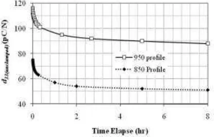
both of the samples decrease to 88 pC/N and 51 pC/N respectively, which correspond to decay rates of 24 % and 32 %. This verified that piezoelectric materials co-fired at a peak temperature of 950 °C perform better than those co-fired at 850 °C.
Fig. 9 shows the measurement results of d33 for clamped and unclamped samples. When substituting the measured value of d33 for clamped samples at 28 pC/N and unclamped samples at 53 p/N into equation (2), the value of d31 can be calculated as -18.8 pC/N.
VI.CONCLUSION
Berlincourt method is a simple measurement method for determining the piezoelectric charge constant, d33, which is a performance indicator for piezoelectric materials. From the experiment, it shows that the value of d33 decay over the time for both clamped and unclamped samples and the different between them is about 45%. The experiment results also verify that the value of d33 for a clamped sample is influenced by the value of d31 as a consequence of the clamping effect.
ACKNOWLEDGEMENT
The authors would like to acknowledge the support of this work by the Faculty of Electronic and Computer Engineering, Universiti Teknikal Malaysia Melaka (UTeM) to present this paper in the conference.
REFERENCES
[1] S.R. Anton and H.A. Sodano, “A review of power harvesting using
piezoelectric materials (2003 –2006),” Smart Materials and Structure,
2007, vol. 16, p. R1 – R21.
[2] H. Jaffe, "Piezoelectric Ceramics," Journal of The American Ceramic Society, vol. 41, pp. 494-498, 1958.
[3] B. Jaffe, W.R. Cook Jr, H. Jaffe, J.P. Roberts and P. Popper,
Piezoelectric Ceramics. London: Academic Press Inc., 1971.
[4] S.L. Kok, N.M White, and N.R. Harris. “A free-standing, thick-film
piezoelectric energy harvester,” in IEEE sensors 2008, 26 – 29 October 2008, Lecce, Italy.
[5] R.N. Torah, S.P. Beeby and N.W. White, "Experimental Investigation into The Effect of Substrate Clamping on The Piezoelectric Behaviour of Thick-Film PZT Elements," J.Phys.D: Appl.Phys., vol. 37, pp. 1-5, 2004.
[6] R. Steinhausen, T. Hauke, W. Seifert, V. Mueller, H. Beige, S. Seifert,
P. Löbmann, "Clamping of piezoelectric thin films on metallic substrates: influence on the effective piezoelectric modulus d33," in Proceedings of the Eleventh IEEE International Symposium on Application of Ferroelectrics, ISAF, Montreux, Switzerland, Aug. 1998, pp. 93-96.
[7] W. P. Mason and H. Jaffe, "Methods for Measuring Piezoelectric,
Elastic, and Dielectric Coefficients of Crystals and Ceramics," Proceedings of the IRE, vol. 42, pp. 921-930, 1954.
[8] R. Torah, S.P. Beeby, and N.M. White, “An improved thick-film piezoelectric material by powder blending and enhanced processing
parameters.” IEEE Trans.Ultrason.Ferroelectr.Freq, Control, 2005.
52(1): p. 10-16.
[9] Cotton, D., Chappell, Paul, A. Cranny, and N. White, “A new binderless thick-film piezoelectric paste.” Journal of Materials Science: Materials in Electronics, 2007. 18(10): p. 1037-1044.
[10] Shepard, J.J.F., Chu, F., I. Kanno, and S. Trolier-McKinstry,
“Characterization and aging response of the d31 piezoelectric
coefficient of lead zirconate titanate thin films.” J.Appl.Physics, 1999. 85(9): p. 6711-6716.
[11] S.L. Kok, N.M. White and N.R. Harris, “Fabrication and characterisation of free-standing thick-film piezoelectric cantilevers for energy harvesting.” Measurement Science and Technology, 2009, vol. 20 (12).
Fig. 6: d33 as a function of time elapsed over 15 minutes for measurements
taken just after polarisation and six months after polarisation for a clamped sample.
Fig. 7: d33 as a function of time elapsed for an unclamped sample just after polarisation and six months after polarisation.
Fig. 8: The d33 value as a function of time elapsed for free-standing samples co-fired at 850 °C and 950 °C.
Fig. 9: Comparison of d33 value between unclamped (free-standing)
samples and clamped sample.