Improved Tracking Capabilities With Collaboration
Multimarker Augmented Reality
Fendi Aji Purnomo
*, P. Insap Santosa
*, Rudy Hartanto
* *Department of Electrical Enginering and Information Technology University of Gadjah Mada, Yogyakarta, Indonesia
Abstract — The most common problem in Augmented Reality (AR) is the inability of detecting marker in different angle to show the expected virtual object. This study has been conducted to improve the ability reading / tracking in order to overcome the inability of AR in marker tracking for different angle. The method is to find the angle of the tracking error with rotation. Based on found angle of each corner and then registering the target image to the same virtual object. The marker is a 3D real object (marker-less) which captured into movie to produce 3D objects with the same condition. The conversion of the target image into multi marker using Vuforia. Testing is conducted with angle tracking variation to the emergence of the virtual object. The result of this study stated that the reading ability can be done by the application of AR which is virtual object appear for tracking variations for angle between 0 and 360.
Keywords - multi marker, tracking improvement, marker angle, augmented reality.
I. INTRODUCTION
Augmented Reality (AR) is a visual technology that combines objects or virtual world into the real world view in real time [1]. AR technology has been developed in many fields such as military, medical, education, engineering, industrial and entertainment. This is due to the advantage of AR technology which allows a user to interact using natural gestures. Camera, as the 'eyes' of the AR technology, take a picture of the marker continously, process and generate a virtual interaction that is seen in the real world on the screen as well as Head Mounted Display (HMD).
The main problem in the AR system is the accuracy in registering 3D objects, which require alignment of virtual objects with the real environment in 3D coordinates. In the analysis of object registration which has been carried out using Super Resolution technique [2] for user with a regular camera or webcam in receiving data which usually requires better hardware requirement. The technique has been analyzing the object tracking on potato marker with distance variations, slope angle, sway and lighting (white). However int tracking process with changes in position has not optimal, causing changes in the virtual objects that appear or are not as expected. In this technique, the use of camera resolution variation has not been analyzed considering the devices are recently equipped with cameras with many resolution.
Increased capability augmented reality system using optical flow has been demonstrated [3] in its outcome presented a real-time augmented reality system based on the marker-less tracking for general purpose applications. The proposed
system leverages the strengths of established techniques Reviews such as SURF and integrates a bi-directional optical flow algorithm for improving the performance of the system.
In this paper, the research will be done to improve the system capability of Augmented Reality in object tracking for a wide range of angles by utilizing the tracking error angle. So that the user is expected to perform tracking in different positions.
II. AUGMENTED REALITY
Augmented Reality (AR) is a technology that allows a computer to display the virtual objects accurately in a real object in real time. AR system was first developed in Sutherland in 1965, and until now growing rapidly in many fields such as medicine, manufacturing, entertainment, etc. Until recently the development of AR continues to occur, but the focus of the development of the AR itself according [4] broadly divided into three areas, namely tracking technology, appearance technology and interaction technology.
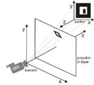
In AR systems, the coordinate system that is used is a model a pinhole camera [5]. Which at this model, the positive z-axis is in the front and as the reference is marker position seen from the camera.
As seen in Figure 1, for each markers and cameras has a different orientation positions. Both systems use a camera marker and right handed (positive z-axis in front) and the results of image captured by the camera is projected onto viewplane using perspective projection.
Fig. 1. Coordinate system of AR environment
In displaying 3D objects that correspond to the position and orientation of the marker, taking into account the results
Page 225 of 436
received viewplane projection (projection field on the screen) and then displayed. According to [6] in addition to the 2D projection on the field, the marker and the camera shifts to consider changes in the position and rotation of the 3D coordinate system. In displaying 3D objects that correspond to the position and orientation of the marker, taking into account the results received viewplane projection (projection field on the screen) and then displayed. As is the case, we need to know where a particular point of a real object will be projected in the image or vice versa. Therefore, the projection from 3D to 2D space needed is calculated. This projection can be explained using the matrix M. Projective indicated by the intrinsic matrix A and matrix extrinsic [R | T].
...(1) Intrinsic matrix contains specific values of a particular camera, the focal length parameters fx and fy and sheer value s and the center points ux and uy camera. Extrinsic parameters indicate the coordinate system transformation from 3D coordinates to real coordinates in 3D camera [7].
To project a virtual object into a real object in AR, the application need a method of tracking. Augmented reality can be classified into two based on the presence or absence of the use of markers, namely: marker and Markerless [8]. Marker can be an image of a real object or an artificial image with a unique pattern. AR marker closely associated with pattern recognition to calculate the position, orientation, and scale of the AR object. On the other hand, Markerless AR tracking method uses a real object in as the marker or without the use of artificial markers.
A good marker is one that is easily recognizable and reliable in any condition [9]. For example, in low light condition and the position of the moving camera, a good marker will be preserved by the AR system. Therefore, a good marker has a complex texture.
The working principle is simple, that is, when an AR application finds a match with the identification of markers, either through marker-based tracking and Markerless. Thus, the application can perform a certain action. For example, if the application recognizes a specific marker, then the application will display information AR-coated (overlay) on top of the image marker identified. Furthermore, the AR application can display various types of information, such as playing an audio or video clip associated with the marker, displaying information about historical facts relating to the location, 3D models, and so forth.
III.METODE The stage of the research is as follows: Application development stage
Fig. 2 Research methods
The use of 3D Markerless will be a video aimed at getting the ideal marker conditions. Markerless not affected to changes in light.
Fig. 3 3D markerless
Fig. 4 Full Feature 3D markerless by Vuforia
This study aims to find the angle of the tracking error and then register the image of the traget at any angle to the same virtual object.
The algorithm method in this study using the SIFT Vuforia SDK. SIFT (Scale invariant Feature Transform) is a method takes the feature points that exist in an image, to help ensure the matching of feature points of an object on a different point
Making AR applications (Image targeting)
Additional features Auto focus
The angle of each error tracking
registering the target image / multi-marker for each angle error
Markerless tracking Testing (0-360 degrees) to the distance, occlusion and tilt or movement
Page 226 of 436
of view [10]. This approach change an image into a large collection of local feature vectors, each of which is invariant to translation, scaling, and rotation of the image, and some lighting changes and invariant 3D projection [11].
The testing phase is done by reading Markerless starting from the point 0 to the 360 degrees of distance tracking (Fig 5). The y-axis as the axis of rotation Markerless. Oclution and tilt testing is also given in the test to determine the stability of tracking.
Marker rotated 0-360 degrees Camera
Fig. 5 Markerless testing phase
IV.RESULTS AND DISCUSSION Table 1. Angle Tracking Results
Angle D1 D2 D3 D4 D5 D6
0 1 1 1 1 1 1
5 1 1 1 1 1 1
10 1 1 1 1 1 1
15 1 1 1 1 1 1
20 1 0 0 0 1 1
25 0 0 0 0 1 0
30 0 0 0 0 0 0
With : 1 = Tracking found 0 =Tracking lost
Table 1 shows that the maximum AR application tracking capabilities at an angle of 15 degrees, thus making multimarker done every 15 degree intervals.
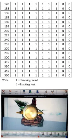
Table 2. Markerless tracking test chart from 0 to 360 degree angle to the distance
Distance (cm)
angle
10
20
30 40 50 60
70 80 90
0
1
1
1
1
1
1
1
0
0
15
1
1
1
1
1
1
1
0
0
30
1
1
1
1
1
1
1
0
0
45
1
1
1
1
1
1
1
0
0
60
1
1
1
1
1
1
1
0
0
75
1
1
1
1
1
1
1
0
0
90
1
1
1
1
1
1
1
0
0
105
1
1
1
1
1
1
1
0
0
120
1
1
1
1
1
1
1
0
0
135
1
1
1
1
1
1
1
0
0
150
1
1
1
1
1
1
1
0
0
165
1
1
1
1
1
1
1
0
0
180
1
1
1
1
1
1
1
0
0
195
1
1
1
1
1
1
1
0
0
210
1
1
1
1
1
1
1
0
0
225
1
1
1
1
1
1
1
0
0
240
1
1
1
1
1
1
1
0
0
255
1
1
1
1
1
1
1
0
0
270
1
1
1
1
1
1
1
0
0
285
1
1
1
1
1
1
1
0
0
300
1
1
1
1
1
1
1
0
0
315
1
1
1
1
1
1
1
0
0
330
1
1
1
1
1
1
1
0
0
345
1
1
1
1
1
1
1
0
0
360
1
1
1
1
1
1
1
0
0
With : 1 = Tracking found 0 =Tracking lost
Fig 6. Tracking markerless by system
Testing with the occlusion is by occlusion Markerless surface features up to 50%, a virtual object may still appear and closing 75% of the virtual object features already started missing.
Testing such a tilt that camera shake by hand, for small vibrations can still maintain the appearance of virtual objects and a large and rapid vibrations causing the virtual object does not appear.
V. CONCLUSION
This study has shown that the use of multimarker to bring the same virtual object can be done. Tracking markers can be
Page 227 of 436
read from 0 to 360 degree angle. Optimal tracking at range of 10 to 70cm.
REFERENCE
[1] Azuma, A. (1997), Survey of Augmented Reality, Presence: Teleoperators
and Virtual Environments 6, 4, 355 – 385, 1997.
[Online] Available :
http://www.cs.unc.edu/~azuma/ARpresence.pdf [2] Liegsalz, F, Evaluation of The Impact of Super
Resolution on Tracking Accuracy, Ottobrunn: tum.de, 2012. [Online] Available : https://campar.in.tum.de/twiki/pub/Students/MaSuperR esoultionOnTracking/a00460.pdf
[3] Herakleous, K & Poullis, Cimproving Augmented Reality Applications With Optical Flow, IEEE 2013, 978-1-4799-2341-0
[4] Feng. Z, Henry, B.D, Mark, B. 2008 , Trends In Augmented Reality Tracking, Interaction And Display: A Review Of Ten Years Of ISMAR, Singapore : Nanyang Technology University, 2008.
[5] Persa. S., Sensor Fusion in Head Pose Tracking for Augmented Reality, Wöhrmann Print Service, 2006.
[Online] Available
http://homepage.tudelft.nl/c7c8y/Theses/PhDThesisPer sa.pdf
[6] Kato. H., Billinghurst, M. Poupyrev, I. Tetsutani, N. dan Tachibana, K., Tangible Augmented Reality, Nagoya, Japan : Proceedings of Nicograph, 2001. [7] R. Hartley and A. Zisserman, "Multiple View
Geometry in Computer Vision," Cambridge University Press, pp. 155-157, 2003.
[8] Geroimenko, V. (2012). Augmented Reality
Technology and Art: The Analysis and Visualization of Evolving Conceptual Models. Information Visualisation (IV), 2012 16th International Conference (pp. 445-453). IEEE.
[9] Siltanen, S. (2012). Theory and applications of marker-based augmented reality. Finland.
[10] David G. Lowe, Object Recognition from Local Scale-Invariant Features, Computer Science Department, University of British Columbia, 2004.
[11] Mohamed Aly, “Face Recognition using SIFT
Features”, CNS186 Term Project, Winter 2006.