i
GAS POWERED MODEL CAR
MOHD NURAFIZ BIN HUSSEIN
This thesis report submitted to Faculty of Mechanical Engineering in partial fulfillment of the requirements for the award of Bachelor’s Decree of Mechanical
Engineering (Thermal-Fluids)
Faculty of Mechanical Engineering Universiti Teknikal Malaysia Melaka (UTeM)
ii
”I hereby to declare that the work is my own except for summaries and quotations which have been duly acknowledged”
iii
ACKNOWLEDGEMENT
Alhamdulillah, Thanks to almighty Allah god of the all universe for the blessing for me to finish the report for Projek Sarjana Muda (PSM).
First of all, my greatest thank to my project supervisor, Dr. Mohd Yusoff Bin Sulaiman for his valuable suggestion and advice throughout the project. He also helps in obtaining the reference and through the manuscript of this report. Not forgotten to all the technician whom has help me in fabricating the project.
iv
ABSTRACT
v
ABSTRAK
vi
TABLE OF CONTENTS
CHAPTER CONTENT PAGES
ACKNOWLEDGEMENT iii
ABSTRACT iv
ABSTRAK v
TABLE OF CONTENT vi
LIST OF TABLES x
LIST OF FIGURES xi
LIST OF APPENDICES xiv
1 INTRODUCTION 1
1.1 Overview 1
1.2 Problem Statement 2
1.3 Objective 3
1.4 Project Scope 3
2 LITERATURE REVIEW 4
vii
2.1.1 Introduction 4
2.1.2 Two-Stroke Engine 6
2.1.3 Four-Stroke Engine 7
2.2 Model Car Engine 7
2.2.1 Nitro Engine System 8
2.2.2 Fuel Feed System 10
2.2.3 Nitro Fuel 12
2.2.4 Glow Plug 14
2.3 Nitro Engine Part 15
2.3.1 Cylinder Head 16
2.3.2 Carburetor 16
2.3.3 Cranckshaft 17
2.3.4 Crankcase 18
2.3.5 Exhaust Port 18
2.4 Liquid Petroleum Gas 19
2.4.1 Liquid Petroleum Gas Properties 19 2.4.2 Liquid Petroleum Gas Temperature And 20
Pressure
2.5 Gas Engine 21
2.5.1 Filter 21
2.5.2 Hose, Pipe and Fitting 22
2.5.3 LPG Tank 22
viii
2.5.5 Converter 24
2.5.6 Mixer 24
2.5.7 Injector 25
2.5.8 Electrical and Electronik Control 25
3 METHODOLOGY 27
3.1 Gathering Information 27
3.2 Design 28
3.3 Selection of Suitable Component 28
3.4 Arrangement of LPG Component 29
3.4.1 LPG Tank Installation 29
3.4.2 LPG Control Valve 31
3.4.3 Hose 32
3.5 Ignition System 32
3.5.1 Magneto Ignition Module 33
3.6 Lubricant System 35
3.6.1 Component Selection 35
3.6.2 System Arrangement 36
3.7 Analyzing Design System Performance 38 3.7.1 Equipment Use for Experiment 39 3.7.2 Experiment of Engine Speed 39
3.7.3 Experimental Procedure 40
ix
4 EXPERIMENTAL RESULT AND DISCUSSION 42
4.1 Fabrication Process 42
4.1.1 Ignition System 43
4.1.2 LPG System 44
4.2 Experiment 45
4.2.1 Experimental Result 46
5 CONCLUSION AND RECOMMENDATION 47
5.1 Conclusion 47
5.2 Recommendation 48
5.2.1 Improving the Ignition System 49 5.2.2 Designing the LPG Control Valve 49 5.2.3 Analyzing the Gas Properties 50
REFERENCE 51
RUJUKAN 53
x
LIST OF TABLES
NO. TITLE PAGES
3.1 Example of Engine Speed Table 40
4.1 Engine Speed Table 46
xi
LIST OF FIGURES
NO. TITLE PAGES
2.1 Step of Piston Rotation 9
2.2 Port in Cylinder 10
2.3 Small Engine Crank-Shaft 11
2.4 Open Crank-shaft 11
2.5 Basic Engine Parts 16
2.6 Carburetor Part 17
3.1 LPG System Design Flow Chart for RC Engine 28
3.2 LPG Components Assembly’s Flow Chart in RC Engine 29
3.3 Gas Cartridge 30
3.4 Portable Gas Stove 30
3.5 Slip Type Carburetors 31
xii
3.7 Nylon Hose 32
3.8 Schematic Arrangement of Electronic Ignition System 33
3.9 Magneto Ignition Module with Spark plug 34
3.10 Position of Pickup Sensor 34
3.11 Principle of Pascal’s Law 35
3.12 Nitro Fuel Tank 36
3.13 Lubricant Oil Flow Chart 37
3.14 Flow Chart of Experimental Process 38
3.15 Tachometer 39
3.16 System Schematic Diagram 40
4.1 Marking of TDC Point 43
4.2a Original Plug holder 43
4.2b Fabricated plug Holder 43
4.3 Installation of Ignition System 44
4.4 LPG System 45
4.5 Graph Speed versus Control Valve Turn for Tank Valve Turn is ¼ 47
xiii 4.7 Graph Speed versus Control Valve Turn for Tank Valve Turn is ¾ 48
4.8 Graph Speed versus Control Valve Turn for Tank Valve Turn is 1 48
4.9 Graph Speed versus Control Valve Turn 49
5.1 Electronic Ignition Module 55
xiv
LIST OF APPENDICES
NO TITLE PAGES
A FLOW CHART FOR PSM 1 56
B FLOW CHART FOR PSM 2 57
C GANT CHART FOR PSM 1 58
D GANT CHART FOR PSM 2 58
E JURNAL
F PROPANE, BUTANE AND LPG DATA 60
G OWNER INSTRUCTION MANUAL 63
H ENGINE TECHNICAL SPECIFICATION 64
1
CHAPTER I
INTRODUCTION
1.1 Overview
Model car most frequently refers to scale miniatures of real production vehicles, designed as kits for the enthusiast to construct. They can be created in plastic, die-cast metal, even wood. Though most car models are static display items, individual model builders have sometimes powered their vehicles in various ways, including rubber bands, springs, inertia mechanisms, electric motors, internal combustion engines, air engines and steam engines.
Small model internal combustion (IC) engines used to powered model car have similar system as real IC engine where the engine was driven by the combustion in the cylinder. There are two type of small IC engine use to supply power to radio control (RC) model which is:
• Two-stroke • Four-stroke
2
power to undergo high speed. Nitro fuel can supplied more power to the engine but it is very expensive and hazardous. Therefore it is not suitable if use for spend time at the back yard.
LPG is the popular alternative fuel been used since the 1940s for spark ignition engines. Using LPG can reduce the fuel consumption close to half as much fuel compare with nitro. LPG also was widely used in this country, so it is easier to get supply compared with nitro oil.
Refer to above statement, it believe that designing a small IC engine powered by gas (LPG) is an effective yet commercialize way for RC car user beside control the emissions of harmful pollution.
1.2 Problem Statement
For all this time, LPG had been strongly promote by the car manufacture and government as it reduce the fuel consumption and reduces the emissions of harmful pollutants. However, there are several parts to be considered before designing the engine powered by gas.
The first factor to identify is to decide type of engine suitable for model car. There are several type of engine was design and the most suitable for model car is two-stroke RC Nitro Engine.
The problem of current system is the RC engine use nitro fuel and it ignited by glow spark. The purpose of this project is to apply the gas power in RC engine by installing appropriate part. As a result, a design of RC engine that can be powered by gas is proposed by:
i. Changing the ignition system from glow plug to spark plug ii. Prepare a small tank for gas
3
1.3 Objective
The main objective of this study is:
• To apply the LPG in internal combustion engine
1.4 Project Scope
The scope of this project generally involved the following: • To study an existing model car engine design
4
CHAPTER II
LITERATURE REVIEW
2.1 Internal Combustion Engine
2.1.1 Introduction
The internal combustion engine is an engine in which the combustion of a fuel occurs with an oxidizer (usually air) in a combustion chamber. In an internal combustion engine the expansion of the high temperature and pressure gases, which are produced by the combustion, directly applies force to a movable component of the engine, such as the pistons or turbine blades and by moving it over a distance, generate useful mechanical energy.
All internal combustion engines depend on the exothermic chemical process of combustion: the reaction of a fuel, typically with oxygen from the air (though it is possible to inject nitrous oxide in order to do more of the same thing and gain a power boost). The combustion process typically results in the production of a great quantity of heat, as well as the production of steam and carbon dioxide and other chemicals at very high temperature.
5
petroleum gas, and the rarer use of propane. Except for the fuel delivery components, most internal combustion engines that are designed for gasoline use can run on natural gas or liquefied petroleum gases without major modifications. Large diesels can run with air mixed with gases and a pilot diesel fuel ignition injection. Liquid and gaseous bio-fuels, such as ethanol and biodiesel can also be used. Some engines with appropriate modifications can also run on hydrogen gas.
Internal combustion engines require ignition of the mixture, either by spark ignition (SI) or compression ignition (CI). Gasoline engine ignition systems generally rely on a combination of a lead-acid battery and an induction coil to provide a high-voltage electrical spark to ignite the air-fuel mix in the engine's cylinders. This battery is recharged during operation using an electricity-generating device such as an alternator or generator driven by the engine. Gasoline engines take in a mixture of air and gasoline and compress it to not more than 12.8 bar (1.28 MPa), then use a spark plug to ignite the mixture when it is compressed by the piston head in each cylinder.
Diesel engines and HCCI (Homogeneous charge compression ignition) engines rely solely on heat and pressure created by the engine in its compression process for ignition. The compression level that occurs is usually twice or more than a gasoline engine. Diesel engines will take in air only, and shortly before peak compression, a small quantity of diesel fuel is sprayed into the cylinder via a fuel injector that allows the fuel to instantly ignite. HCCI type engines will take in both air and fuel but continue to rely on an unaided auto-combustion process, due to higher pressures and heat. This is also why diesel and HCCI engines are more susceptible to cold-starting issues, although they will run just as well in cold weather once started. Light duty diesel engines with indirect injection in automobiles and light trucks employ glow plugs that pre-heat the combustion chamber just before starting to reduce no-start conditions in cold weather.
6
running auxiliary electrical components and accessories. Most new engines rely on electrical and electronic control systems that also controls the combustion process to increase efficiency and reduce emissions.
The term internal combustion engine usually refers to an engine in which combustion is intermittent, such as the more familiar four-stroke and two-stroke piston engines.
2.1.2 Two-Stroke Cycle
Engines based on the two-stroke cycle use two strokes (one up, one down) for every power stroke. Since there are no dedicated intake or exhaust strokes, alternative methods must be used to scavenge the cylinders. The most common method in spark-ignition two-strokes is to use the downward motion of the piston to pressurize fresh charge in the crankcase, which is then blown through the cylinder through ports in the cylinder walls. Spark-ignition two-strokes are small and light (for their power output), and mechanically very simple. Common applications include snowmobiles, lawnmowers, weed-whackers, chain saws, jet skis, mopeds, outboard motors, and some motorcycles. Unfortunately, they are also generally louder, less efficient, and far more polluting than their four-stroke counterparts, and they do not scale well to larger sizes. Interestingly, the largest compression-ignition engines are two-strokes, and are used in some locomotives and large ships.
7
employ four stroke engines, and smaller two-strokes to be outfitted with catalytic converters in some jurisdictions.
2.1.3 Four-Stroke Cycle
Engines based on the four-stroke cycle or Otto cycle have one power stroke for every four strokes (up-down-up-down) and are used in cars, larger boats and many light aircraft. They are generally quieter, more efficient and larger than their two-stroke counterparts. There are a number of variations of these cycles, most notably the Atkinson and Miller cycles. Most truck and automotive Diesel engines use a four-stroke cycle, but with a compression heating ignition system. This variation is called the diesel cycle.
2.2 Model Car Engine
There are many powered model car been design nowadays. Though most car models are static display items, individual model builders have sometimes powered their vehicles in various ways, including rubber bands, springs, inertia mechanisms, electric motors, internal combustion engines, air engines and steam engines. The common use for powered model car is internal combustion engine and electric motor.
8
and the internal wear surface of the cylinder is plated with chrome. This hard chrome plating offers a much better wear surface than the soft brass underneath, and helps to prolong engine life.
2.2.1 Nitro Engine System
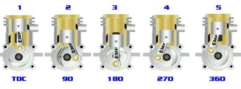
Nitro engine is a small IC engine that powered by combustion of nitromethane in combustion chamber (cylinder). These engines use two-stroke system to operate the engine. Two-Stroke engines only have one cycle to produce power and no cams. This single cycle can be divided into two strokes. The combustion occur when the air/fuel mixture in the combustion chamber were compressed by the piston to the top dead center. The exhaust gases occur from combustion rapidly expanding in combustion chamber will increase in pressure, forced the piston down. When piston move down, it will uncover the exhaust port on the side of the sleeve. This opening will make the exhaust gases escape through the manifold.
9
Figure 2.1 Step of Piston Rotation
(Source: http://www.nitrorc.com/articles/2strokepart1a.html)
1. Piston reach top dead center – combustion occurs
2. Piston move down uncovering the exhaust port – exhaust gases escape to atmosphere 3. Piston move down uncovering the sleeve intake port – air/fuel mixture entering the
combustion chamber.
4. Piston move up covering the sleeve intake port
5. Piston move up covering the exhaust port – pressurize the mixture and ignition occur
Other part to be considered is engine timing. Engine timing is what determines the opening and closing time of the engine's ports. On 4-stroke engines, timing is controlled by the cams that open and close the valves at predetermined sequences to bring a fresh air/fuel charge in and to exhaust it out the manifold. On 2-Stroke engines there are no cams, belts or gears the engine timing is occur when the piston is moving inside the sleeve. Piston covers and uncovers a series of ports that either let air and fuel in or allow burnt combustion products out. It is the geometry of these ports that determines the timing of the engine.
10
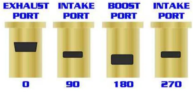
[image:24.612.143.459.218.373.2]opening on top of the crankshaft, called the intake port, is also measured in degrees of crank-shaft rotation. Engine builders try to stay within a certain range for both the intake and the exhaust timing of an engine for reliability and ease of tuning. Engine timing can be modified by engine experts. This usually affects the RPM/Torque curve of an engine to better suit the intended use of the engine. The timing also affects the required length of the tuned pipe.
Figure 2.2 Port in Cylinder
(Source: http://www.nitrorc.com/articles/2strokepart1a.html)