i
COMPACT MICROSTRIP ARRAY ANTENNA USING ELECTROMAGNETIC BAND GAP (EBG)
SHARIFAH RASHIDAH BT. SYED HUSIN
This Report Is Submitted In Partial Fulfillment of Requirements for the Bachelor Degree of Electronic Engineering (Telecommunication Electronic)
Fakulti Kejuruteraan Elektronik dan Kejuruteraan Komputer
Universiti Teknikal Malaysia Melaka
ii
UNIVERSTI TEKNIKAL MALAYSIA MELAKA
FAKULTI KEJURUTERAAN ELEKTRONIK DAN KEJURUTERAAN KOMPUTER
BORANG PENGESAHAN STATUS LAPORAN
PROJEK SARJANA MUDA II
Tajuk Projek : ………
Sesi
Pengajian :
1 2 / 1 3
Saya ………..
(HURUF BESAR)
mengaku membenarkan Laporan Projek Sarjana Muda ini disimpan di Perpustakaan dengan syarat-syarat kegunaan seperti berikut:
1. Laporan adalah hakmilik Universiti Teknikal Malaysia Melaka.
2. Perpustakaan dibenarkan membuat salinan untuk tujuan pengajian sahaja.
3. Perpustakaan dibenarkan membuat salinan laporan ini sebagai bahan pertukaran antara institusi
pengajian tinggi.
4. Sila tandakan ( √ ) :
SULIT*
*(Mengandungi maklumat yang berdarjah keselamatan atau kepentingan Malaysia seperti yang termaktub di dalam AKTA RAHSIA RASMI 1972)
TERHAD** **(Mengandungi maklumat terhad yang telah ditentukan oleh
organisasi/badan di mana penyelidikan dijalankan)
TIDAK TERHAD
Disahkan oleh:
__________________________ ___________________________________
(TANDATANGAN PENULIS) (COP DAN TANDATANGAN PENYELIA)
Tarikh: ……….. Tarikh: ………..
COMPACT MICROSTRIP ARRAY ANTENNA USING ELECTROMAGNETIC BAND GAP (EBG)
iii
“I hereby declare that this report is the result of my own work except for quotes as cited in the reference”
Signature :
iv
“I hereby declare that I have read this report and in my opinion this report is sufficient in
terms of the scope and quality for the award of Bachelor of Electronic
Engineering (Telecommunication Electronics) With Honors”
Signature :
Supervisor’s Name : MR MOHD SA’ARI BIN MOHAMAD ISA
v
vi
ACKNOWLEDGEMENT
First, I would like to thank and praise to ALLAH S.W.T for given me the ability to complete this report and project successfully. Without it, I would not have been able to come this far.
I would like to express my special gratitude and thanks to my supervisor Mr
Mohd Sa’ari Bin Mohamad Isa for his advice, understanding, well guidance and help
throughout this project.
A special thanks to my family especially my parents for the encouragement and inspiration. Not forgotten to all my fellow friends for their brilliant idea and support. Lastly, my heart goes to all who have directly or indirectly helped me to make this project success.
vii
ABSTRACT
viii
ABSTRAK
ix
TABLE OF CONTENTS
CHAPTER CONTENTS PAGE
TITLE i
STATUS CONFORMATION REPORT FORM ii
DECLARATION iii
DEDICATION v
ACKNOWLEDGEMENT vi
ABSTRACT vii
ABSTRAK viii
TABLE OF CONTENTS ix
LIST OF TABLES xii
LIST OF FIGURES xiii
I INTRODUCTION
1.1 Introduction 1
1.2 Problem Statement 2
1.3 Objectives 3
1.4 Scope of Project 3
1.5 Project Planning 6
x
II LITERETURE REVIEW
2.1 Antenna 8
2.2 Antenna Properties 9
2.3 Microstrip Patch Antenna 11
2.4 Advantages and Disadvantages of Microstrip Antenna 13
2.5 Feeding Techniques 14
2.6 Radiation Mechanism 15
2.7 Microstrip Antenna Array 15
2.8 Mutual Coupling 16
2.9 Electromagnetic Band Gap (EBG) 16
2.10 Surface Wave Current 18
III METHODOLOGY
3.1 Project Methodology 20
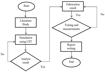
3.2 Flow Chart 21
3.3 Literature study of the antenna 23
3.4 Design and Simulation 23
3.5 Fabrication Process 28
3.6 Measurement Process 30
IV RESULT AND DISCUSSION
4.1 Single Microstrip Patch Antenna 33
4.1.1 Calculation of Microstrip Patch Antenna 34 4.1.2 Calculation of Ground Plane size 36 4.1.3 Single Microstrip Patch Antenna Dimension and
Result
xi
4.2 Microstrip Patch Antenna Array 39
4.2.1 Simulation 41
4.2.2 Measurement 42
4.3 Electromagnetic Bandgap (EBG) 44
4.3.1 Simulation 46
4.4 Microstrip Array Antenna with EBG 48
4.4.1 Simulation 49
4.4.2 Measurement 52
4.5 Comparison between Microstrip Patch Antenna Array with and without EBG
55
V CONCLUSION
5.1 Conclusion 58
5.2 Proposed Future Work 59
xii
LIST OF TABLES
NO. TITLE PAGE
4.1 Parameter of Microstrip Patch Antenna 34
4.2 Dimension of Single Patch Antenna 38
4.3 Comparison parameter of single patch antenna 39
4.4 Dimension of Antenna Array 40
4.5 Result of antenna array 42
4.6 Comparison between antenna array with and without EBG simulation and measured.
44
4.7 Dimension of Mushroom-like EBG surface 45
4.8 Dimension of Uni-planar EBG surface 46
4.9 Dimension of antenna array with and without EBG 49
4.10 Result of microstrip antenna array with EBG 50
4.11 Comparison between antenna array with EBG simulation and measured.
53
4.12 Comparison between antenna array with and without EBG simulation and measured.
xiii
LIST OF FIGURES
NO. TITLE PAGE
1.1 Top View 5
1.2 Front View 5
1.3 Side View 5
1.4 Flow chart of project 6
2.1 2D radiation pattern 9
2.2 Radiation lobes 10
2.3 Graph of Return Loss vs Frequency 11
2.4 Microstrip patch antenna structure 12
2.5 Various shapes of microstrip patch atenna 13
2.6 Microstrip feed line 14
2.7 Coaxial feed 14
2.8 Radiation mechanism of microstrip patch antenna
15
2.9 Various types of EBG structure 17
2.10 EBG structure 18
2.11 Propagation of surface waves in substrate 18 2.12 Propagation surface wave with and without
EBG
19
3.1 Methodology flow chart 21
xiv
3.3 Antenna (planar) template 25
3.4 Layout based simulation 25
3.5 Create a brick layout 25
3.6 Transient and Frequency Domain Solver Parameters layout
26
3.7 Field monitor layout 26
3.8 S-Parameter result layout 27
3.9 Screenshot of the Impedance Calculation 27
3.10 UV light generator 28
3.11 Developer acid 29
3.12 Etching tank 29
3.13 Dryer 29
3.14 Solder iron 30
3.15 Microstrip antenna array 30
3.16 Antenna array being test with network analyser 31
3.17 Measurement setting 32
3.18 Antenna array with EBG in H and E plane 32
4.1 Single patch antenna design layout 37
4.2 Single patch antenna design layout with ground above substrate
37
4.3 S11 of single patch antenna (formula) 38
4.4 S11 of single patch antenna (optimize) 39
4.5 Antenna array dimension 40
4.6 S-parameters of antenna array (simulation) 41
4.7 Gain of antenna array 41
4.8 Comparison S11 between simulation and measured
43
4.9 Comparison S12 between simulation and measured
43
4.10 Mushroom-like EBG surface 45
xv
4.12 Reflection phase of a mushroom-like EBG 47
4.13 Reflection phase of a uni-planar EBG 47
4.14 (a) Microstrip patch array antenna (b) EBG and
EBG’s ground plane
48
4.15 S-parameters of microstrip antenna array with EBG (simulation)
49
4.16 Gain and directivity of microstrip antenna array with EBG
50
4.17 E-Polar radiation pattern 51
4.18 E-Cross Polar radiation pattern 51
4.19 H-Polar radiation pattern 51
4.20 H-Cross Polar radiation pattern 51
4.21 Comparison S11 between simulation and measured
52
4.22 Comparison S12 between simulation and measured
53
4.23 E-Polar radiation pattern 54
4.24 E-Cross Polar radiation pattern 54
4.25 H-Polar radiation pattern 54
4.26 H-Cross Polar radiation pattern 54
4.27 Comparison S11 between simulation and measured for antenna array with and without EBG
56
4.28 Comparison S12 between simulation and measured for antenna array with and without EBG
1
CHAPTER 1
INTRODUCTION
1.1Introduction
The antenna is being developed due to the popularity in a wireless communication system and device. Antenna applied to the traditional radio, TV broadcast and wireless communication [1]. Microstrip patch antenna is a low profile radio antenna that is very popular in mobile and radio wireless communication. It can be mounted on a metal ground plane and consists of a flat rectangular of metal [2]. Microstrip patch antenna has more benefit compared to conventional antenna [3]. Patch antenna advantages such as easy to fabricate, lighter in weight, analysis, low cost and simple feeding structure [2, 4]. Moreover, this antenna can provide circular polarization, dual frequency operation and frequency agility [3]. However, it has narrow bandwidth, low efficiency, low gain and surface wave losses [4].
2
antenna. The surface waves can be reduces if the directing electromagnetic wave propagates along ground plane and can increase back lobe which reduce signal to noise ratio. In addition, EBG structures reduce the mutual coupling and design low profile antennas with good radiation efficiency [1].
Previous project consist of 2 layers EBG substrates that implement with microstrip patch. The results produces higher gain with wider impedance bandwidth compared to conventional patch antenna [6]. Other than that, there are 4 elements array antenna using EBG that place on a ground plane. This structure can improve performance in antenna array elements, return loss and VSWR [7]. Mutual coupling of an antenna can be reduce by 2 layers EBG that provide lower resonant frequency [8].
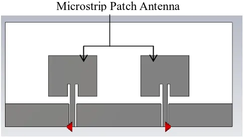
This project will use two patch antennas and placed it above EBG. Mutual coupling is occurring when 2 antennas placed nearer. The array element is inserted with EBG to reduce mutual coupling [9]. In this paper, high impedance EBG is used on the ground plane and simulates and measured microstrip patch antenna with EBG. Simulation using CST to optimized the antenna parameters and fabricated using FR4 PCB. The frequency range of the antenna in this paper is 2.4Hz. The size of the antenna can affect the frequency range. The antenna range with EBG ground plane is designed to function both inside and outside the bandgap[10].
1.2Problem Statement
3
antennas are placed nearer and cannot be placed in a very compact arrangement [12]. Mutual coupling cause some losses in power and radiation pattern in the antenna [4]. The effect of mutual coupling can be reduces by added EBG. In addition, it can suppress the surface waves design low profile antenna with good radiation efficiency [5]. Hence improve the radiation pattern and gain [4]. The radiation pattern and return loss will be obtained by simulation and measurement.
1.3Objectives
The main objective of this project is to design and develop compact microstrip array antenna with the implemented of Electromagnetic Band Gap (EBG). The EBG structure within the microstrip patch element will be investigate. The result is analysed by using the simulation in CST software. Next, the performance of the array antenna will be compared for the integration with and without electromagnetic band gap (EBG). The design antenna structure is fabricating using FR4 PCB. Lastly, the result for both simulation and measure is compare.
1.4Scope of Project
This final year project is beginning with literature study regarding the topic. It focuses on the development of the antenna to meet the desired performance that can use in 2.4GHz.
The research is about microstrip patch antenna, array antenna and electromagnetic band gap (EBG). Antenna efficiency, radiation pattern, gain and mutual coupling need to be studied first for both single microstrip patch antenna and array antenna. There are several advantages when EBG is placed on the microstrip patch antenna. Therefore, EBG structure is the important element in this literature study.
4
CST software will be used for the simulation to design microstrip patch antenna and EBG. CST is most accurate an efficient computational to provide the variety tools for the antenna design. Before designing antenna, obtain the frequency for antenna and band gap. CST used to design single antenna and to optimize the result for achieving the centre frequency of 2.4GHz. The band gap of EBG will cover the frequency of array antenna which is 2.2GHz to 2.6GHz. From the single antenna, build array antenna. The distance between the array antennas is varied to analyse the mutual coupling, efficiency and gain. Moreover, CST is used to combine antenna array and EBG simulation. Place array antenna above EBG to analyse the performance on mutual coupling, gain, return loss and many more.
Fabrication is required after designed the antenna using CST in 2.4GHz resonant frequency. The substrate material of the antenna is FR4 board with dielectric constant 4.3 and thickness 1.6mm. There are several steps in fabrication. The steps are printed the layout design, expose the board to the ultra violet light, etching and lastly soldering.
5
Figure 1.1: Top View.
Figure 1.2: Front View.
Figure 1.3: Side View.
Microstrip PatchAntenna
EBG
Microstrip Patch Antenna EBG
6
1.5Project Planning
The project begins with literature study according to the topic that related. The research is about microstrip patch antenna, array antenna and electromagnetic band gap (EBG). Specification and calculation of the antenna was obtained from the research. After that, design single antenna, array antenna and EBG using CST software. Next, analyse the result of comparison between the array antenna performance with and without EBG. The fabrication process of the antenna can be done when all the specification meets the requirement. Next process is the measurement process of both array antenna with and without EBG. Lastly, the result between simulation and measurement of the antenna is compared. All the experimental results are included in this thesis report.
7
1.6Organisation of Report
This report contain of five chapters which describe all the job process that has been done in PSM 1 and PSM 2. The chapter describes as follows.
Project introduction are describe in the first chapter. This chapter includes the objectives, problem statement, project planning and scope of projects. The work flow of this project is set up according to objective and scope of projects.
In chapter two, it consists of literature review. The theory is based on the microstrip patch antenna, array antenna and electromagnetic band gap (EBG).
The methodology is described in chapter 3. In this chapter it explains the steps to complete this project. It begins with the literature review, simulation using CST software and followed by fabrication and measurement. Design procedure of the antenna is included in this chapter. Steps of simulation, fabrication and measurement process are discussing in this chapter.
Chapter 4 is about result and discussion of the project. It includes the result of measurement and simulation of the antenna. This chapter discuss regarding simulation and measurement of single patch antenna, antenna array, electromagnetic band gap and antenna array using EBG.
8
CHAPTER 2
LITERATUE REVIEW
2.1Antenna
Antenna defined as a device that used for receiving and radiating an
electromagnetic wave in free space [13]. An antenna definition according to Webster’s
Dictionary is “a usually metallic device for receiving or radiating radio waves” [11]. Meanwhile, IEEE defines the antenna as “a means for radiating or receiving radio
waves”. In IEEE the standards used is IEEE Std 145-1983 [11]. In transmitter, an
9
2.2Antenna Properties
There are several properties to determine antenna performance. There are gain, radiation pattern, efficiency, surface wave and bandwidth.
The radiation pattern is defined as a “radiation properties of the antenna in
graphical representation as a function of space coordinates” [11]. It describes of how the antenna radiates energy and it is present in the far field. The information is presented in the form of horizontal and vertical [11]. Radiation pattern parts are referred as lobes that consist of major and minor as show in figure 2.2. Back lobes and side lobes are consider as minor lobes. A radiation lobe is a part of radiation pattern that bounded by regions of relatively weak radiation intensity. Direction of maximum radiation is major lobe. Meanwhile, minor lobe is the undesired direction of antenna radiation [11].
![Figure 2.1: 2D radiation pattern [11].](https://thumb-ap.123doks.com/thumbv2/123dok/532583.61671/24.612.193.481.335.482/figure-d-radiation-pattern.webp)
