CR-Form-v3
CHANGE REQUEST
OWS Common
CR ?
rev-
Current version: 1.1.0 For HELP
on using this form, see bottom of this page or look at the pop-up text over the symbols.
Proposed change affects: AS Imp Spec X Best Practices Paper Other
Title: OWS Common change request: Add general reference systems
Source: Arliss Whiteside, Peter Baumann, Coverages WG
Work item code: Date: 2008-01-21
Category: B
Use one of the following categories: F (Critical correction)
A (corresponds to a correction in an earlier release) B (Addition of feature),
C (Functional modification of feature) D (Editorial modification)
Reason for change: A Coordinate Reference System (CRS) as specified in ISO 19111 and GML 3.1+ is limited to spatial-temporal axes, without any axis redundancy. However, OGC specifications, such as GML, WCS, and WMS, could effectively use “coordinates” based on more general reference systems. Definitions of such general reference systems have now been defined in draft OGC Abstract Specification Topic 19 [OGC 08-008].
Consequences if
not approved:
Continue living with OGC specification limitations and inefficiencies due to a Coordinate Reference System (CRS) being limited to spatial-temporal axes, without any axis redundancy (see proposed Subclause D.18)
Clauses affected: 3, 10.1 through 10.3, D.18 (new), owsGeneralReferenceSystems.xsd (new)
Other specs X Other core specifications GML, WCS, WMS
Affected: Abstract specifications Best Practices Papers
Supporting Doc.
Other comments:
Status
Disposition
Add the attached new XML Schema Document named
“owsGeneralReferenceSystems.xsd” to the current set of these
documents for OWS Common 1.1.0 (OGC 06-121r3).
Expand, renumber, and edit as follows Subclauses 10.1 through 10.3 of
OWS Common 1.1.0:
10 Other operation parameters
10.1 Introduction
This clause specifies some other parameters used in multiple OWSs by multiple operation requests and responses, including:
a) General reference systems
b) Bounding boxes
c) Coordinate reference system references d) Lists of references
e) Format parameters f) Data descriptions
10.2 General reference systems
10.2.1 Overview
This subclause builds on the draft OpenGIS® Abstract Specification Topic 19: General
Reference Systems [OGC 08-008], which proposes extensions to OGC Abstract Specification Topic 2 — Spatial referencing by coordinates. These extensions allow specifying much more general reference systems, beyond the constraints of ISO 19111 and 19111-2. A Coordinate Reference System (CRS) as specified in ISO 19111 is limited to spatial-temporal axes, without any axis redundancy.
That draft document specifies a General Reference System which need not be spatial or temporal, and may contain multiple axes. That document also specifies a General
Compound Reference System which may add one or more General Reference Systems to a compound coordinate reference system. Furthermore, a General Compound Reference System may include redundant axes in the spatial, temporal, and general reference systems that are combined, when that is useful.
10.2.2 XML encoding
The XML Schema fragment for encoding a GeneralCompoundRS and a GeneralRS shall be as specified in the attached owsGeneralReferenceSystems.xsd file. Notice that this XML Schema Document defines both GeneralCompoundRSType and GeneralRSType, which may be used as the types of XML elements with application-specific names other than GeneralCompoundRS and GeneralRS.
EXAMPLE 1 An example of XML encoded GeneralRS is: <?xml version="1.0" encoding="UTF-8"?>
<GeneralRS xmlns="http://www.opengis.net/ows/1.2" xmlns:gml="http://www.opengis.net/gml"
xmlns:xsi="http://www.w3.org/2001/XMLSchema-instance" xsi:schemaLocation="http://www.opengis.net/ows/1.2 ../owsGeneralReferenceSystems.xsd"
gml:id="temperatureCentigradeRS">
<gml:srsName>temperatureCentigrade</gml:srsName> <usesGeneralCS>
<GeneralCS gml:id="temperatureCentigradeCS"> <gml:csName>temperatureCentigrade</gml:csName> <gml:usesAxis>
<gml:CoordinateSystemAxis gml:uom="degreesCentigrade" gml:id="degreesCentigrade">
<gml:name>degreesCentigrade</gml:name>
<gml:remarks>The zero value meaning is well-known: the freezing point of water on surface of earth geoid. </gml:remarks>
<gml:axisAbbrev>C</gml:axisAbbrev>
<gml:axisDirection>warmer</gml:axisDirection> </gml:CoordinateSystemAxis>
</gml:usesAxis> </GeneralCS>
</usesGeneralCS> </GeneralRS>
EXAMPLE 2 An example of XML encoded GeneralCompoundRS is: <?xml version="1.0" encoding="UTF-8"?>
xmlns:gml="http://www.opengis.net/gml" <componentRS xlink:href="urn:ogc:def:crs:EPSG:6.1:4326"/> <componentRS>
<GeneralRS gml:id="temperatureCentigradeRS">
<gml:srsName>temperatureCentigrade</gml:srsName> <usesGeneralCS>
<GeneralCS gml:id="temperatureCentigradeCS"> <gml:csName>temperatureCentigrade</gml:csName> freezing point of water on surface of earth geoid. </gml:remarks>
<gml:axisAbbrev>C</gml:axisAbbrev>
10.3.1 General Basic bounding box parameters
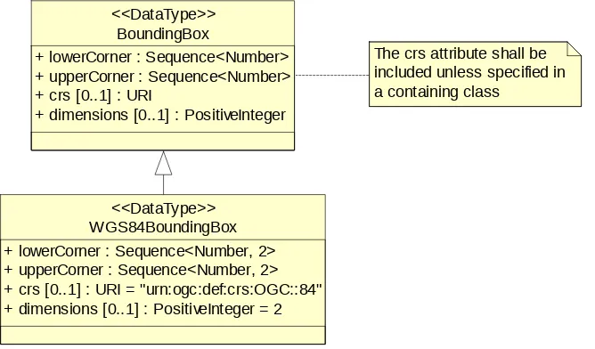
A general (basic) bounding box is one type of bounding box that may be used by various operations in various OWSs. This very general bounding box data type is adapted from gml:EnvelopeType in GML 3.1 [OGC 03-105r1]. Each general bounding box data structure shall contain the parameters described in Figure 1 and specified in Table 1.
WGS84BoundingBox + lowerCorner : Sequence<Number, 2> + upperCorner : Sequence<Number, 2> + crs [0..1] : URI = "urn:ogc:def:crs:OGC::84" + dimensions [0..1] : PositiveInteger = 2
<<DataType>> BoundingBox
+ lowerCorner : Sequence<Number> + upperCorner : Sequence<Number> + crs [0..1] : URI
+ dimensions [0..1] : PositiveInteger <<DataType>>
The crs attribute shall be included unless specified in a containing class
Table 1 — Parameters included in general BoundingBox data type
Names Definition Data type Multiplicity and use
lower Corne r
Lower Corn er
Coordinates of bounding box corner at which the value of each coordinate normally is the algebraic minimum within this bounding box a
Ordered sequence of
Coordinates of bounding box corner at which the value of each coordinate normally is the algebraic maximum within this bounding box a
Ordered sequence of double values b
One (mandatory)
crs crs
Reference to definition of the CRS used by the Lower Corner and UpperCorner coordinates
URI Zero or one (optional)
Omitted only
The number of dimensions in this CRS
(the length of a coordinate sequence) Positive integer Zero or one (optional) c
a Values other than the minimum and maximum shall be used as discussed in Subclauses 10.2.43.6 and D.13. b Any number of axes may be used, from 1D to 4D or more. The number of axes included, and the order of these axes, shall be as specified by the referenced CRS.
c This number is specified by the referenced CRS definition, but may also be specified here.
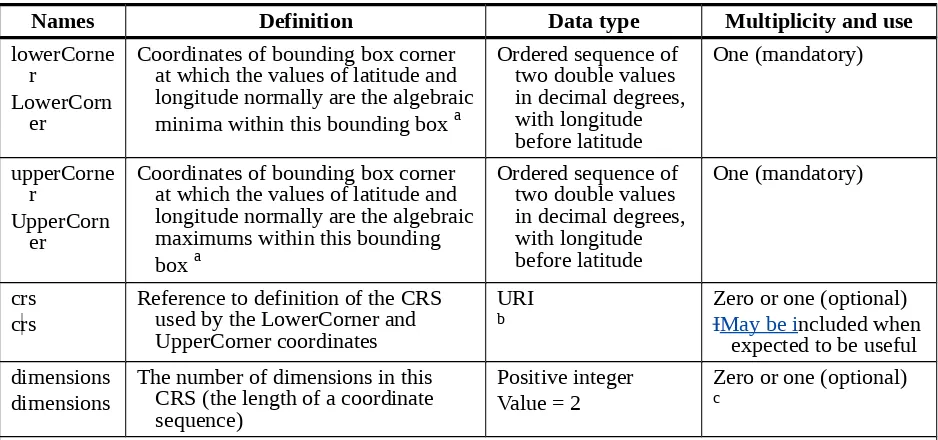
10.3.2 WGS 84 bounding box parameters
A WGS 84 bounding box is another type of bounding box that is expected to be used by various operations in various OWSs. This type is simplified from the general (basic)
bounding box data type defined in Subclause 10.23.1, for use only with the 2D
Table 2 — Parameters included in WGS84BoundingBox data type
Names Definition Data type Multiplicity and use
lower Corne r
Lower Corn er
Coordinates of bounding box corner at which the values of latitude and longitude normally are the algebraic minima within this bounding box a
Ordered sequence of
Coordinates of bounding box corner at which the values of latitude and longitude normally are the algebraic maximums within this bounding box a
Reference to definition of the CRS used by the Lower Corner and UpperCorner coordinates
URI
b Zero or one (optional)IMay be included when
expected to be useful dimensions
dimensions
The number of dimensions in this CRS (the length of a coordinate sequence)
Positive integer Value = 2
Zero or one (optional)
c
a Values other than the minimum and maximum shall be used as discussed in Subclauses 10.23.5 6 and D.13. b Reference to 2D CRS using WGS 84 datum with longitude before latitude in decimal degrees, as specified in Subclause 10.34.
c The number “2” is specified by the WGS 84 2D CRS definition, but may also be specified here.
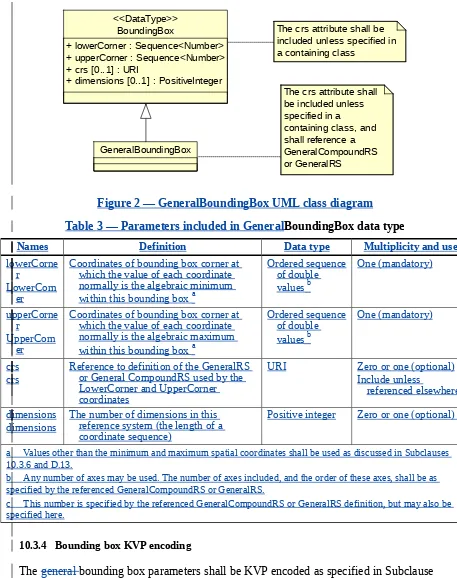
10.3.3 General bounding box parameters
The crs attribute shall be included unless specified in a containing class
BoundingBox
+ lowerCorner : Sequence<Number> + upperCorner : Sequence<Number> + crs [0..1] : URI
+ dimensions [0..1] : PositiveInteger <<DataType>>
GeneralBoundingBox
The crs attribute shall be included unless
Figure 2 — GeneralBoundingBox UML class diagram
Table 3 — Parameters included in GeneralBoundingBox data type
Names Definition Data type Multiplicity and use lower Corne
r
Lower Corn er
Coordinates of bounding box corner at which the value of each coordinate normally is the algebraic minimum
within this bounding box a
Coordinates of bounding box corner at which the value of each coordinate normally is the algebraic maximum
within this bounding box a
Reference to definition of the GeneralRS or General CompoundRS used by the Lower Corner and UpperCorner coordinates
URI Zero or one (optional)
Include unless
referenced elsewhere
dimensions dimensions
The number of dimensions in this reference system (the length of a coordinate sequence)
Positive integer Zero or one (optional) c
a Values other than the minimum and maximum spatial coordinates shall be used as discussed in Subclauses 10.3.6 and D.13.
b Any number of axes may be used. The number of axes included, and the order of these axes, shall be as specified by the referenced GeneralCompoundRS or GeneralRS.
c This number is specified by the referenced GeneralCompoundRS or GeneralRS definition, but may also be specified here.
10.3.4 Bounding box KVP encoding
The general bounding box parameters shall be KVP encoded as specified in Subclause 11.5.3 for a parameter value containing an (ordered) list. For a (basic) or general bounding box, the listed values shall be for the ordered quantities:
LowerCorner coordinate 3 ...
LowerCorner coordinate N UpperCorner coordinate 1 UpperCorner coordinate 2 UpperCorner coordinate 3 ...
UpperCorner coordinate N crs URI (optional)
This list allows N coordinates for each corner, listed in the order specified by the
associated referenced CRS, GeneralCompoundRS, or GeneralRS. The “dimensions” parameter shall be omitted in KVP encoding. The exact number of coordinates specified by the associated CRS, GeneralCompoundRS, or GeneralRS shall be included. A parser may determine the number of dimensions, and whether or not the optional CRS crs URI is present, by counting the number of items in the list. If there are an odd number of items, then a CRS crs URI is present. The number of remaining items divided by two indicates the number of dimensions of the bounding box.
The CRS crs URI value usually references an instance of the definition of a CRS, as specified in [OGC Topic 2]. Such a CRS definition may be XML encoded using the gml:CoordinateReferenceSystemType in [GML 3.1.1]. For well known references, it is not required that the CRS “crs” definition exists at the location the URI points to. If no
CRS crs URI value is included, the applicable CRS must be either:
a) Specified outside the bounding box, but inside a data structure that includes this bounding box, as specified for a specific OWS use of this bounding box type b) Fixed and specified in the Implementation Specification for a specific OWS use of
the bounding box type
A WGS 84 bounding box shall be KVP encoded in a corresponding parameter value list, with the ordered listed values for the quantities:
LowerCorner longitude, in decimal degrees LowerCorner latitude, in decimal degrees UpperCorner longitude, in decimal degrees UpperCorner latitude, in decimal degrees
crs URI = “urn:ogc:def:crs:OGC:1.3:CRS84” (optional)
NOTE The OGC URN “urn:ogc:def:crs:OGC:1.3:CRS:84” is here used to refer to the “WGS 84 longitude-latitude” CRS specified in Subclause B.3 of WMS 1.3, previously referenced as “CRS:84”.
The CRS crs URI may be included when considered useful. When included, this CRS crs
Both All three types of bounding boxesparameters may use application-specific parameter names which are not specified here, but shall be specified for each bounding box used in each specific OWS Implementation Specification. An Implementation Specification may specify a KVP encoding of an operation request that contains more than one bounding box parameter. An Implementation Specification shall specify when a KVP encoded bounding box is limited to, or shall be interpreted as, a WGS 84 bounding box.
EXAMPLES Two Eexamples of KVP encoded bounding boxes are: VWXYZWGS84BOX=71.63,41.75,-70.78,42.90
ABCDEBOX=189000,834000,285000,962000,urn:ogc:def:crs:OGC:1.3:CRS84
NOTE In the second example, the colons in the CRS URI must be escaped by “%3A”, as required in KVP encoding. The resulting encoding is “ABCDEBOX=189000,834000,285000,962000, urn%3Aogc %3Acrs%3AOGC%3A1.3%3ACRS84”. See 11.3 for more on reserved characters and URL encoding.
10.3.5 Bounding box XML encoding
The XML Schema fragment for encoding either a general basic or a WGS 84 bounding box shall be as specified in the attached owsCommon.xsd file. Notice that this XML Schema Document defines both BoundingBoxType and WGS84BoundingBoxType, which may be used as the types of XML elements with application-specific names other than BoundingBox and WGS84BoundingBox.
EXAMPLE 1 Two An examplesof XML encoded (plain) BoundingBox bounding boxises are: <?xml version="1.0" encoding="UTF-8"?>
<BoundingBox xmlns="http://www.opengis.net/ows/1.1" xmlns:xsi="http://www.w3.org/2001/XMLSchema-instance"
xsi:schemaLocation="http://www.opengis.net/ows/1.1 owsCommon.xsd" crs="urn:ogc:crs:EPSG:6.3:26986" dimensions="2">
<!-- Example. Primary editor: Arliss Whiteside. Last updated 2005-01-25 --> <LowerCorner>189000 834000</LowerCorner>
<UpperCorner>285000 962000</UpperCorner> </BoundingBox>
EXAMPLE 2 An example XML encoded WGS 84BoundingBox is:
<?xml version="1.0" encoding="UTF-8"?>
<WGS84BoundingBox xmlns="http://www.opengis.net/ows/1.1" xmlns:xsi="http://www.w3.org/2001/XMLSchema-instance"
xsi:schemaLocation="http://www.opengis.net/ows/1.1 owsCommon.xsd">
<!-- Example. Primary editor: Arliss Whiteside. Last updated 2004/10/13. --> <LowerCorner>-71.63 41.75</LowerCorner>
<UpperCorner>-70.78 42.90</UpperCorner> </WGS84BoundingBox>
The XML Schema fragment for encoding a general bounding box shall be as specified for the GeneralBoundingBox element in the attached owsGeneralReferenceSystems.xsd file. Again, this XML Schema Document defines the GeneralBoundingBoxType, which may be used as the type of XML elements with application-specific names other than
GeneralBoundingBox.
<GeneralBoundingBox xmlns="http://www.opengis.net/ows/1.2" xmlns:gml="http://www.opengis.net/gml"
xmlns:xsi="http://www.w3.org/2001/XMLSchema-instance" xsi:schemaLocation="http://www.opengis.net/ows/1.2 ../owsGeneralReferenceSystem.xsd" ="TBD" dimensions="5"> <LowerCorner>999 999 999 999 999</LowerCorner>
<UpperCorner>999 999 999 999 999</UpperCorner> </GeneralBoundingBox>
10.3.6 Bounding box use
Bounding boxes may be repeated wherever useful in a specific OWS Implementation Specification. Wherever a specific OWS allows the bounding box to be repeated, that Implementation Specification shall specify how multiple bounding boxes shall be
interpreted, by OWS clients and/or servers. One expected use is meaning the union of the areas defined by multiple listed bounding boxes. That meaning is expected to be often useful in describing the region(s) covered by geospatial data sets.
The coordinates of each bounding box corner are normally the algebraic minimum and maximum inclusive values of the position coordinates of all the data within this bounding box. For features, these minimum and maximum values shall be computed from all the positions in all included geometries, including the lines connecting adjacent recorded points. For grid coverages, these values shall be computed from the positions of all the grid points, including the areas of all the grid cells with corners at recorded grid points.
NOTE In keeping with ISO 19123, a grid coverage bounding box includes only the grid points at the corners (not the centres) of the grid cells. The bounding box of a grid coverage extends only as far as the outermost grid points. It does NOT include any area (partial or whole grid cells or sample spaces) beyond those grid points.The bounding box of a grid coverage does NOT include rectangular areas centered on the grid points. This grid coverage bounding box is based on the CV_GridEnvelope class specified in
Subclause 8.4 of ISO 19123, and discussed in Subclause 8.2.2 of that document.
The general bounding box contents defined will not always specify the MINIMUM rectangular BOUNDING region, if the referenced CRS uses an Ellipsoidal, Spherical, Polar, or Cylindrical coordinate system, as those terms are specified in OGC Abstract Specification Topic 2. Specifically, this box will not specify the minimum rectangular bounding region surrounding a geometry whose set of points span the value discontinuity in an angular coordinate axis. Such axes include the longitude and latitude of Ellipsoidal and Spherical coordinate systems. That geometry could lie within a small region on the surface of the ellipsoid or sphere.
If the data for which a bounding box is needed is continuous around the continuous angular axis of an Ellipsoidal, Spherical, Polar, or Cylindrical coordinate system, the bounding box limits for that angular axis shall be set to minus and plus infinity.
EDITOR’S NOTE The Harmonization working group decided to NOT NOW specify a bounding
box structure that may always specify the MINIMUM rectangular region SURROUNDING data within a limited region that crosses a value discontinuity. The following paragraph thus specifies that each specific OWS Implementation Specification shall suitably address this issue.
some (or all) allowed CRSs. If the minimum rectangular bounding region shall be allowed for some CRSs, that specific OWS Implementation Specification shall also specify how that can be done when the referenced CRS allowed uses an Ellipsoidal, Spherical, Polar, or Cylindrical coordinate system.
There are a variety of possible approaches to allowing specification of the minimum rectangular bounding region when the referenced CRS uses an Ellipsoidal, Spherical, Polar, or Cylindrical coordinate system. Subclause D.13 (informative) summarizes the known alternatives for handling the case where the minimum region crosses the value discontinuity in a longitude or other continuous axis, and recommends the first two listed alternatives.
10.4 Coordinate reference system references
10.4.1 Overview
This subclause specifies two alternative ways to reference a CRS, GeneralCompoundRS,
or GeneralRS in OWS operation requests and responses. One frequent use will be referencing the Reference System (CRS) for a server input or output; another use will be referencing the CRS for a bounding box. In most cases, these ways will be used to identify the referenced CRS, and not to transfer a definition of that CRS. Subclause D.14 summarizes many of the requirements considered when specifying how to reference
CRSs. Much of this material is also applicable to referencing CRS components and Coordinate Operations and their components.
A specific OWS shall always reference a CRS,GeneralCompoundRS, or GeneralRS by using an XML attribute or element with the type anyURI. Such an anyURI value may be used to reference a CRS whether the definition of that CRS is included in the same data transfer, is NOT included in the same data transfer, cannot be electronically accessed, or can be electronically accessed.
NOTE 1 In XML Schemas, the anyURI data type is the standard way to briefly reference (or cite) something specified elsewhere. XML attributes with type anyURI include the GML 3.1.1 defined attributes named gml:srsName, gml:uom, xlink:href, and gml:codeSpace.
When using a XML attribute or element with the type anyURI to reference a CRS or CRS-related object, that URI shall have a value which uses one of two alternative URI formats:
a) Universal Resource Locator (URL), with standard form. The URL format should be used whenever the referenced definition is known to be electronically available using this standard URL.
NOTE 2 Two widely-used forms of URI are URL and URN. We are specifying using URNs as the way of citing CRS-related definitions that are "well-known" but are not adequately electronically available using a URL.
NOTE 3 Use of URNs is expected to be more common than use of URLs, and specific OWS Implementation Specifications are expected to specify many standard URN values.
10.4.2 URL references
For all XML attributes and elements with the anyURI data type, a URL value may be used, and often should be used, to reference a definition that is known to be always available using this URL. When not in the same XML document, those definitions shall be electronically available over the Internet using this URL, to both client and server software including multiple clients and multiple servers that must interoperate. The available definitions shall be encoded in XML, using one or more Application Schemas based on the CRS Schemas in [GML 3.1.1].
Such a URL value shall reference either a:
a) Document that defines only the referenced object, optionally including definitions of all or some of its components
b) Dictionary document containing multiple objects, also referencing the specific object within that dictionary using its gml:id value
NOTE Such a dictionary containing multiple objects, or document that defines only one object, could be stored at an OGC supported URL, possibly within the directory now accessible at
http://schemas.opengis.net/.
c) Web service that stores definitions, where the URL value references a GetXxxx operation and provides all the operation parameters needed to retrieve the referenced object
d) Elsewhere in the same XML document, either in a:
1) Logically appropriate place defined by an XML Schema
2) Metadata element encoded within an XML element that includes all the references to those object definitions, such as the outer-most element of the XML document
EDITOR’S NOTE The Harmonization working group decided to NOT NOW define how a server
shall use such a URL in order to be considered compliant with an OWS Implementation Specification. The following paragraph thus specifies that each specific OWS Implementation Specification shall suitably address this issue.
Wherever a specific OWS Implementation Specification allows such a URL to be used, it shall specify how servers shall use those URLs in order to be considered compliant with that specification. There are several alternative approaches to compliant server uses of such transferred URLs, as briefly described in Subclause D.14.6.
10.4.3 URN references
URN values defined by the OGC shall be as specified in OGC Best Practices Paper [05
-023r107-092r1].
Add the following new Subclause D.18 to OWS Common 1.1.0:
D.18 Reasons for general reference systems
A Coordinate Reference System (CRS) as specified in ISO 19111 and GML 3.1.1 and 3.2.1 is limited to spatial-temporal axes, without any axis redundancy. However, several OGC specifications, such as GML, WCS, and WMS, could effectively use “coordinates” based on more general reference systems. This subject is more completely discussed in Annex B of “OpenGIS® Abstract Specification Topic 19: General Reference Systems”
[OGC 08-008].
Add the following normative reference to Clause 3 in OWS Common
1.1.0:
OGC 05-103, The OpenGIS® Abstract Specification Topic 2: Spatial referencing by
coordinate