Underground Leachate Distribution Based on Electrical Resistivity
Tomography in Piyungan Landill, Bantul
Harjito, Suntoro,Totok Gunawan and M.Maskuri
Received: January 2017 / Accepted: Oct 2017 / Published online: ... © 2018 Faculty of Geography UGM and he Indonesian Geographers Association
Abstract his research was conducted in Piyungan Landill, this research aims to identify areas that experience ground-water pollution and spread direction of leachate to the surrounding area caused by leachate movement, and to develop a leachate management model. his research uses Electrical Resistivity Tomography (ERT) survey in order to identify the distribution of electrical resistivity in polluted areas. he results show that groundwater contamination has occurred in the research area, as indicated by very low electrical resistivity in aquifer zone, i.e. 3-9 Ωm. Such low electrical re-sistivity is caused by increased ions in groundwater as the results of leachate migrating downward into groundwater. he increased ions will trigger an increase in electrical conductivity (EC), i.e. up to 1,284 μmhos/cm, and a decline in electrical resistivity. he leachate spreads westward and northward at a depth of 6-17 m (aquifer) with a thickness of pollution between 4-11 m. he recommended landill management model, emphasizing on leachate movement, include base lining (liner), leachate collection channel, geomembrane cap, and leachate treatment.
Abstrak Penelitian ini dilakukan di Tempat Pembuangan Akhir (TPA) sampah Piyungan,dengan tujuan mengidentiikasi
daerah yang mengalami pencemaran airtanah dan arah persebaran yang diakibatkan oleh pergerakan lindi, serta mem-buat model pengelolaan air lindi. Metode yang digunakan dalam penelitian ini yaitu survei electrical resistivity tomography (ERT). Hasil penelitian menunjukkan bahwa telah terjadi pencemaran terhadap airtanah ditandai dengan adanya nilai resistivitas yang sangat rendah di zona akuifer antara 3-9 Ωm. Rendahnya nilai resistivitas ini disebabkan oleh adanya peningkatan ion-ion dalam airtanah yang disebabkan masuknya air lindi ke dalam airtanah. Meningkatnya ion-ion ini akan memicu terjadinya peningkatan daya hantar listrik (DHL) hingga mencapai 1284 μmhos/cm dan menurunkan ting-kat resistivitas. Pola penyebaran air lindi adalah ke barat dan utara pada kedalaman akuifer 6-17 meter, dengan ketebalan pencemaran antara 4-11 meter. Model pengelolaan yang terkait dengan pergerakan air lindi dilakukan dengan membuat pelapisan dasar, membuat saluran lindi, melakukan penutupan akhir menggunakan geomembran dan pengolahan lindi.
Keywords: Piyungan Landill, Groundwater, Leachate, Electrical Resistivity, ERT
Kata kunci: TPA Piyungan, Airtanah, Lindi, Resistivity,ERT
1.Introduction
Groundwater low is a media that has a continuous inluence on the surrounding underground environment. Poor and polluted water quality afects the environment negatively. Leachate fuses into groundwater, lowing from one place to another, in order to erase the energy diference between leachate and groundwater. It is found at the bottom of landill. It seeps through the under lying soil layers. When it seeps through them, many chemical and biological elements that iniatially present in it will be released into the surrounding soil layers through iltration and absorption whose rates depend on the characteristics of the soil. In order to identify areas that experience leachate-contaminated groundwater, this research uses Electrical Resistivity Tomography [Cyril Chibueze Okpoli, 2013].
Harjito, Suntoro and M.Maskuri
Department of Environmental Science, Sebelas Maret University, Surakarta, Indonesia
Totok Gunawan
Department of Geography Information Science, Universitas Gadjah Mada, Yogyakarta, Indonesia
Corresponding email: [email protected]
One of many factors that frequently cause problems in landills is leachate, which is alarmingly mobilized into soil layers and aquifer layers. Piyungan Landill is constructed to accommodate the disposal of wastes from Yogyakarta City, Sleman Regency, and Bantul Regency. he overland low that passes through landills and potentially dissolves organic and anorganic materials in a high concentration is referred to as leachate.
he most likely emerging environmental problem is leachate migration from landill to soil layer and groundwater. Leachate is a liquid waste produced by water lowing from external sources into the piles of waste, which then rinses and dissolves the materials inside the piles; therefore, leachate has varied organic and inorganic pollutant content. When rainwater comes into direct contact with waste, most of its water content converts to runof and experiences evapotranspiration. he remaining water iniltrates into a pile of wastes. Leachate occurs when the capacity of waste materials to retain water (ield capacity) is exceeded.
Leachate is a liquid material that has a high concentration of organic contents originating in landill through which rainwater passes. Aside from the high organic contents, the environmentally harmful nature
Indonesian Journal of Geography Vol. ..., No...., ... (... - ...)
of leachate is also caused by the presence of metallic substances (e.g., Cr+6) [Irhamni et al.,2017]. A poor treatment leads to the iniltration of leachate into the ground and groundwater pollution in the surrounding area. Leachate is a potential problem because it spreads both laterally and vertically depending on the characteristics of the surrounding materials. he quantity (discharge) and quality of leachate luctuate signiicantly because they depend on rainfall and the character of waste materials. he relationship between the amount of rainwater and the discharge of leachate is necessary to understand in order to design the capacity of leachate treatment facility as well as the pollutant load of related leachate.
2.he Methods
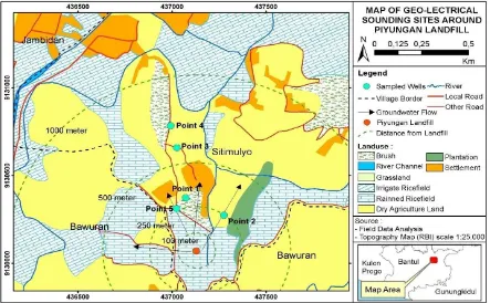
he Electrical Resistivity Tomography (ERT) method in this research applies Wanner Array electrode to obtain primary data from direct measurement at the ield [Oladapo et al., 2013]. It irstly determines ive measuring points, which are located on the north, west, east, and center of the landill. he measuring points provide information on areas with the greatest and smallest pollutant anomaly by interpreting the diference of electrical resistivity levels acquired from geo-electrical sounding [G. Tamma Rao et al.,2013].
he electrical resistivity of clean water is between 10-100 ohm-m [Loke, 2000], which is the base value for determining which point has the greatest or the smallest pollutant anomaly and for identifying the spread direction of leachate. he tools used in this research are GPS Garmin Vista, compass, roll-up tape
measure, and ERT Geoelectric Instrument. ERT is utilized for assessing the layers of materials beneath the land surface based on the characters of their electrical resistivity [Telford et al., 2004].
Electrical resistivity (ρ) is based on electrical current (I) and electrical potential diference (V), which are obtained from direct measurement at the ield [Okan Evans Onojasun, 2015]. Electrical current and electrical potential diference are acquired through injecting electrical current underground using pairs of current electrodes (C1, C2) and potential electrodes (P1, P2) [Loke, 2012; Vincent Bichet, Elise Grisey, Loti Aleya, 2016].
Data Acquisition
Electrical current is injected through a set of electrodes arranged in Dipol-Dipole coniguration [Loke, 2000] (Figure 2). Electrical current lows through a circuit, as illustrated in Figure 2. Current electrode pairs (C1, C2) are placed in a wider distance than potential electrode pairs (P1, P2). he distance between the current electrode pairs (AB or L) is wider in order to measure the electrical resistivity of deeper materials. When electrical potential diference becomes diicult to measure, the sensitivity of the measuring instrument decreases; hence, the distance between potential electrode pairs (MN or a) has to be widened. he electrical current and electrical potential diference for every distance formed between current electrodes and potential electrodes is observed in order to calculate the pseudo-electrical resistivity of the materials of the research area. Data acquisition is conducted at ive
measuring points throughout Piyungan Landill. he reasons location reasons are the location should be open and not close to the power line,the length and width of the location should be suicient for the span of the cable geoelectric survey,the ground surface is not covered by cement or asphalt as it will complicate when electrode insertion, there are no puddles as they may endanger safety,location does not endanger the survey, e.g. areas prone to landslides or very clifs and the location is not a funeral area. hese points are distributed evenly in all under lying geological Formations in the research area is a Semilir Formation composed of rocks consisting of breccias between breccia, breccia tuf, tuf, tuf andesite and tuf dacite and tuf in clay [Rahardjo, et al, 1995 in Sismanto, 2004].
Data Processing
Data acquisition process results in electrical current (I) and electrical potential diference (V) [Lowrie,W, 2014; Eugeniusz Koda et.al, 2017]. However, data processing requires pseudo-electrical resistivity instead of these two data. Pseudo-electrical resistivity (ρa) is calculated based on electrical current and electrical potential diference using the following equations: R = , (1.1)
ρa = , (1.2) ρa = . (1.3)
In inverse modeling technique, the inversion process of pseudo-electrical resistivity is conducted using Res2DINV in computer program. his process aims to convert pseudo-electrical resistivity into the actual electrical resistivity of the materials.[Walid Al-Fares,2014; George Vargemezis et.al, 2015]
Data Analysis Technique
In order to identify the location of leachate accumulation, this research uses quantitative descriptive analysis, i.e. an analysis technique for understanding the distribution of electrical resistivity in polluted areas. Every material has its own range of electrical resistivity. A lower electrical resistivity than the inherent range of related materials indicates the presence of leachate
[Umar Hamzah, Mark Jeeva and Nur Atikah Mohd Ali, 2014]. For example, a groundwater aquifer (freshwater) with electrical resistivity between 10-100 Ώ m will present a reading of lower than 10 Ώ m if it is polluted [Loke,2000]. Identifying the spread direction of leachate is based on the electrical resistivity pseudo-section and three-dimensional model that are correlated with hydrologic and geologic data. he pseudo-section provides information on both lateral and vertical distribution of electrical resistivity. he distribution is presented in a log data model in order to create a three-dimensional model for either electrical resistivity or material/lithology. he three-dimensional model that has been correlated with hydrologic and geologic data shows the spread direction of the leachate. Laboratory analysis on groundwater quality aims to validate the ERT survey result, which is a quantitative descriptive analysis, with the Regulation of the Ministry of Health No. 492/MenKes/Per/IV/2010 on the Requisite of Drinking Water Quality as reference.
3.Results and Discussion
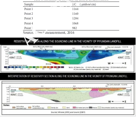
he ERT measurement results show that the distribution of electrical resistivity along the sounding line is between 0.5-800 Ωm. he analysis results of geo-electrical sounding data in the research area show an indication of pollution because leachate in Piyungan Landill seeps through intermittent river system. he intermittent river makes leachate-contaminated water absorbable by the underlying soil through iniltration process, the measurements of leachate in this place show the value 22,565 (µS/cm). his process, then, slowly triggers percolation, i.e., the vertical low of luids or liquid materials into groundwater system. he contamination is indicated by very low electrical resistivity in aquifer zone, i.e., 3-9 Ωm. According to Loke [2000], the value of groundwater resistivity does not experience pollution that is 10-100 Ώ meters, so it is suspected that this groundwater has been polluted due to the movement of leachate water. Results of similar research conducted by Chambers et al., [2006] successfully identiied groundwater pollution in the
Scottish Midland Valley region with a groundwater resistivity value of 2.2-9 Ώ meters.Such low electrical resistivity is caused by increased ions in groundwater as the results of leachate migrating downward into groundwater. he increased ions will trigger an increase in electrical conductivity (EC), i.e. up to 1,284 μmhos/ cm, and a decline in electrical resistivity level.
Groundwater pollution in the area is found at a depth of 6-17 m with a thickness of 4-11 m. he distribution and interpretation of electrical resistivity in this zone are presented in Figure 3.
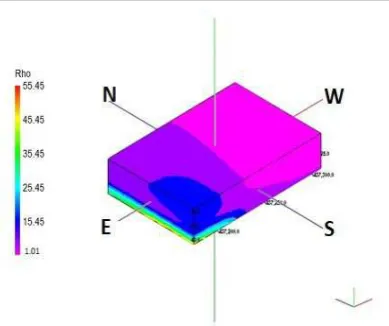
he shape and plume of leachate distribution depend on the concentration of pollutant and the type of groundwater low. Contaminants with high concentration and fast groundwater low result in a big and extensive plume. he model shows the three-dimensional topography of the research area, which describes groundwater low. Based on the three-dimensional model of the distribution of electrical conductivity, the obtained shape and plume are presented in Figure 4. According to the three-dimensional model (Fance model) resulted from ERT survey at G1 and G2 with intersecting lines, the spread direction of leachate is indicated by low electrical
resistivity, as presented in Figure 4.
Figure 4 shows that the lithology of Piyungan Landill consists of either dry or saturated clay, a mix of clay and sand/sandy, and hard rocks at the base. he materials are vertically distributed from soil surface down to 1.5 m in depth. Meanwhile, soil surface with dry clay has an electrical resistivity of 8-20 Ωm with vertical distribution from soil surface to 4 m deep. Beneath this material, there is a mix of clay and sand with electrical resistivity between 20-200 Ωm. It is the primary material and the major composing material of aquifer in the research area. Its thickness is more than 20 m. Meanwhile, the aquifer layers in the area contain sandy clay, which is found at a depth of 6 m from soil surface. he thickness of aquifer along the sounding line is between 14 m and more than 17 m. he last layer at the bottom of the resistivity section has an electrical resistivity of 1,000-8,000 Ωm, which indicates the presence of breccia as the underlying impermeable layer because the study area is located on sediments of young Merapi that lies on Semilir Formation. Semilir Formation is made up from tuf, pumice breccias, tufaceous sandstone, and shale.
Figure 5 shows that the movement of leachate
Table 1. he Electrical Conductivity (EC) in around location
Sample EC ( μmhos/cm)
Point 1 1164
Point 2 1160
Point 3 1284
Point 4 1068
Point 5 982
Source: Direct measurement, 2016
follows the direction of groundwater movement, which is controlled or inluenced by the direction of rock layers. he rock layers around Piyungan Landill have a strike of 900-1050 and a dip of 50-100. he direction of the rock layers show that groundwater in the area tends to low westward and northward. herefore, the leachate in the area lows westward and northward as well, following the direction of groundwater low. he depth of groundwater level in the stratigraphic level is 5.4 m at the east end and 6 m at the west end. he westward and northward groundwater lows tend to cause leachate that seeps into the groundwater system to low westward and northward. he cause of groundwater pollution in the research area is poor leachate treatment. Leachate that comes from a pile of wastes stored in landill requires a proper treatment that can reduce its harmful contents. Ithas to go through a proper treatment process before its disposal. A properly treated leachate will not introduce any pollutants when it seeps into groundwater. Immediate improvement of leachate treatment becomes necessary in order to prevent a wider groundwater pollution.
he landill management model, basing on leachate movement and groundwater system vulnerability,is designed as follows:
Base Lining (Liner)
Inilling requires a base lining system that aims to reduce the mobility of leachate into groundwater. An efective liner prevents pollutants from migrating to the environment, especially groundwater. However, there is empirically no 100% eicient liner system. he discharge of leachate is inevitable, implying the need of leachate collection channel aside from liner system. herefore, the bottom of landill has to be sealed with layers of liner materials to prevent leachate from migrating to outside of the landill and equipped with leachate collection channel. he liner is made of natural materials (e.g., clay, bentonite) or synthetic materials. It may comprise one material (single) or a combination between natural and synthetic materials,
commonly referred to as geocomposite, depending on the necessary functions.
he layer formations and the types of liner materials vary according to the characteristics of solid waste piled on to the landill. R.Kerry Rowe, F.ASCE et al.,2010 recommends that applying single liner system with clay as its material is suicient for city waste. he recommended base lining is geosynthetic or known as lexible membrane liner (FML) [R.Kerry Rowe, F.ASCE et al., 2010]. he commonly used geosyntheticfor base lining is Geotextile as ilter, Geonet as drainage channel, and Geomembrane and geocomposite as bufer layer. Geomembrane, as an impermeable layer, is a geosynthetic made of impermeable polymer. he best polymer is high-density polyethylene (HDPE) that is resistant to chemical reactions occurring in B3 waste. he scheme of double liner system between FML and compacted soil is presented in Figure 6.
Leachate Collection Channel
Leachate collection system is recommended to have holed pipes located inside the rock-coated channels. In addition, it requires coated channels that contain hollow river stones (N.I. husyanthan, S.P.G. Madabhushi, S. Singh,2007). he facilities required for pipe-equipped leachate collection channels are as follows:
Terraced Slope
In order to prevent leachate from accumulating at the bottom of landill, the base of landill is transformed into terraces with certain slope (1-5%) that allows leachate to low into collection channels (0.5-1%). In order to make leachate low into collection or re-circulation unit, every collection channel is equipped with holed pipes. he maximum slope and length of collection channels are designed based on the capacity of collection channel facility. In order to assess this capacity, the research uses Manning’s equation.
Piped Bottom
he bottom of landill is divided into several Figure 4.he three-dimensional pattern of leachate Figure 5.he three-dimensional spread direction of
rectangles with clay divides. he width of the divide depends on the width of the cells. Leachate collection pipes are placed parallel to the length of cells and directly on geomembrane.
Final Cap
he inal cap of landill consists of several parts. he upper part is soil that functions as protection and plant-growing medium (top soil). When soil in the area does not accord to the requisites, it needs an improvement, i.e. by mixing or replacing it with soils from other areas. he thickness of top soil is 60 cm. he layer beneath it functions as drainage system, which drains as much precipitation as possible so that rainwater does not seep into the layer beneath it. he materials used for composing this layer are porous, e.g., sand, gravels, and synthetic materials like geonet. he thickness of this layer is around 30 cm. he second part is leachate-retaining layer, which is commonly composed of geocomposite (geomembrane and compacted clay). he thickness of geomembrane is recommended to be more than 2.5 mm, while the thickness of clay is more than 50 cm. Beneath this layer is the gas ventilation system, which is a requisite for city waste treatment because most of city waste is organic matters that decompose biologically. In aerobic condition, the resultant gas is mainly carbon dioxide and methane. herefore, this biogas can be utilized as an alternative source of energy. he layer of gas ventilation system consists of porous medium like sand/gravel or pipe system. he lowest part of the inal cap is subgrade layer that functions to increase the stability of the surface of landill. Furthermore, it helps to form a necessary slope for accelerating lateral drainage and reducing hydraulic level. Its thickness is 30 cm. Aside from this inal cap, reducing the amount of overland low that enters landill involves slope arrangement, equipped with surface drainage and sowing.
Leachate Treatment
Leachate contains the same composition of liquid domestic waste, but the concentration of its organic matters is higher than a pile of domestic waste, as indicated by the high BOD5 level of leachate, i.e. around 2,000-30,000. Leachate treatment system is
divided into two steps, namely secondary treatment and tertiary treatment. he secondary treatment consists of stabilization pond (facultative and anaerobic) and aeration pond.
4.Conclusion
According to the aforementioned results, the research conclusion is as follows data analysis of geo-electrical sounding in the research area results in indications of pollution. he indications are potentially caused by the presence of leachate originating in Piyungan landill that seeps into intermittent river system, the measurements of leachate in this place show the value 22,565 (µS/cm). he intermittent river makes leachate-contaminated water absorbable by the underlying soil through iniltration process. his process, then, slowly triggers percolation, i.e. the vertical low of luids or liquid materials into groundwater system. Such pollution is indicated by very low electrical resistivity (3-9 Ωm) in aquifer zone.
he leachate spreads westwardat a depth of 6-17 m with a thickness between 4-11 m. he spread direction of leachate in this area is westward, following the direction of groundwater low. he westward and northward groundwater lows tend to cause leachate that seeps into groundwater system to low westward and northward as well.
he landill management model, basing on leachate movement against groundwater system vulnerability, consists of base lining (liner), leachate collection channel, inal cap composed of geomembrane, and leachate treatment.
Acknowledgments
he author would like to thank all of the research assistants: Erik Febriarta, S.Si., Lili Ismangil, Sambodo,S.Si., Roza Oktama., as well as those who have helped the implementation of the research
References
Chambers, J.E., Kuras, O., Meldrum, P.I., Ogilvy, R.D., Hollands, J. (2006). Electrical Resistivity Tomography Applied To Geologic, Hydrogeologic,And Engineering Investigations at A Former Waste-Disposal Site. Journal of Figure 6.he structure of base lining (liner) system [R.Kerry Rowe,
Geophysic, 71 (6), hal. B231–B239.
Cyril Chibueze Okpoli (2013). Application of 2D Electrical Resistivity Tomography in Landill Site: A Case Study of Iku, Ikare Akoko, Southwestern Nigeria. Journal of Geological Research Volume 2013, Article ID 895160, 8 pages http://dx.doi. org/10.1155/2013/895160.
Eugeniusz Koda, Andrzej Tkaczyk, Mariusz Lech and Piotr Osinski (2017). Application of Electrical Resistivity Data Sets for the Evaluation of the Pollution Concentration Level within Landill Subsoil. Applied. Sciences journal. 2017, 7, 262; doi:10.3390/app7030262.
G. Tamma Rao, V. V. S. Gurunadha Rao, G. Padalu, Ratnakar Dhakate and V. Subrahmanya Sarma (2013). Application of electrical resistivity tomography methods for delineation of groundwater contamination and potential zones Arab J Geosci (2014) 7:1373–1384 DOI 10.1007/ s12517-013-0835-3.
George Vargemezis, PanayiotisTsourlos, Antonios Giannopoulos and Pavlostrilyrakis (2015). 3D electrical resistivity tomography technique for the investigation of a construction and demolition waste landill site. Stud. Geophys. Geod., 59 (2015), 461- 476, DOI: 10.1007/s11200-014-0146-5 © 2015 Inst. Geophys. CAS, Prague .
Irhamni, Setiaty Pandia, Edison Purba, Wirsal Hasan (2017). Prosiding Seminar Nasional Pascasarjana (SNP) Unsyiah 2017, April 13, 2017, Banda Aceh, Indonesia (in bahasa Indonesia).
Loke, M.H. (2000). Electrical Imaging Survey for Environmental and Engineering.Studies. Diterima 06 Maret 2009, dari http://www. geometrics.com. Loke, M.H. (2012). Tutorial: 2-D and 3-D Electrical
Imaging Surveys. (110 pp., http://www. geotomosot.com/downloads.php, Tutorial Notes-19th October 2012 update).
Lowrie, W. (2007). Fundamentals of Geophysics.New York: Cambridge University Press.
Milsom, J. (2003). Field Geophysics he Geological Field Guide Series. New York: John Wiley & Sons Ltd.
N.I. husyanthana,,S.P.G. Madabhushia, S. Singh (2007). Tension in geomembranes on landill slopes under static and earthquake Loading-Centrifuge study. Geotextiles and Geomembranes 25 (2007) 78–95.Elsiever Journal.
Oladapo, M.I, Adeoye-Oladapo, O.O., Adebobuyi, F.S. (2013). Geoelectric Study of Major Landills in the Lagos Metropolitan Area,South western Nigeria. International Journal of Water Resources and Environmental Engineering 5 (7), 387-398.
R. Kerry Rowe, F.ASCE1; M. Z. Islam, M.Asce; R. W. I. Brachman; D. N. Arnepalli; and A. Ragab Ewais (2010). Antioxidant Depletion from a High-Density Polyethylene Geomembrane under Simulated Landill Conditions. Journal Of Geotechnical And
Geoenvironmental Engineering.
Sismanto (2004). Estimasi Distribusi Pencemaran Leachate Pada Airtanah dengan Metode Geolistrik Dipole-Dipole di Lokasi TPA Piyungan Yogyakarta. Dalam: Prosiding Seminar Nasional Penelitian Pendidikan dan Penerapan MIPA: Yogyakarta.(in bahasa Indonesia)
Sayed Hemeda (2013). Electrical Resistance Tomography (ERT) Subsurface Imaging for Non- destructive Testing and Survey in Historical Buildings Preservation. Australian Journal of Basic
and Applied Sciences • January 2013.
Okan Evans Onojasun (2015). 2-D Electrical Resistivity Tomography Investigation in Landill Site: A Case Study of Millar Road Landill, Baldivis, Western Australia. International Research Journal of Earth Sciences.
Telford , WM, Geldart, LP, and RE Sherif (2004). Applied Geophysics. Cambridge University Press, London.
Umar Hamzah, Mark Jeeva and Nur Atikah Mohd Ali (2014). Electrical Resitivity Techniques ang Chemical Analysis in he SungaiSedu landill. Asian Journal of Applied Sciences 7(7):518-585. Vincent Bichet,Elise Grisey, Loti Aleya, (2016). Spatial
characterization of leachate plume using electrical resistivity tomography in a landill composed of old and new cells (Belfort, France). Engineering Geology 211 (2016) 61-73.Elsevier Journal.
![Figure 2. he arrangement of electrodes in Dipol-Dipole coniguration forms an electrical circuit [Loke,2000]](https://thumb-ap.123doks.com/thumbv2/123dok/1377197.1514449/3.595.150.428.595.747/figure-arrangement-electrodes-dipol-dipole-coniguration-electrical-circuit.webp)