The journal homepage www.jpacr.ub.ac.id p-ISSN : 2302 – 4690 | e-ISSN : 2541 – 0733
Morphology of TiAlN Thin Film onto HSS as Cutting Tools by
Using Mosaic-Styled Target RF Sputtering Method
Sigit Tri Wicaksono*1, Agung Purniawan1,I G.N.B. Dwistha Prayukti1, Tri Mardji Atmono2
1
Department of Materials and Metallurgical Engineering, Institut Teknologi Sepuluh Nopember, Sukolilo, Surabaya, 60111, Indonesia
2
Pusat Sains dan Teknologi Akselerator, Badan Tenaga Nuklir Nasional (BATAN), Babarsari Yogyakarta, Indonesia
*
Corresponding e-mail: [email protected]
Received 23 February 2016; Revised 30 April 2016; Accepted 30 April 2016
ABSTRACT
High Speed Steel (HSS) has been widely used in manufacturing industry as cutting tools. Several methods have been used to improve the cutting performance of HSS in dry cutting. One of them was by growing a thin layer of hard coating on the contact surface of the cutting tool material. In this research, Titanium Aluminum Nitride (TiAlN) layer were deposited on AISI M41 HSS substrate by using Radio Frequency (RF) sputtering method with mosaic styled of target materials. The aluminum surface area ratios on the Titanium target are 10, 20, 30, and 40 % respectively. The deposition time is 15, 30, and 45 minutes respectively. The formation of TiAlN and AlN crystalline compounds were observed by X-Ray Diffraction method. The morphology of thin film layer with a thickness range from 1.4 to 5.2 µm was observed by using a Scanning Electron Microscopy. It was known that the deposition time affect to the thickness and also the roughness of the layer. The topography images by Atomic Force Microscopy showed that the deposition time of 45 minutes produce the finest layer with the surface roughness of 10.8 nm.
Keywords: mosaic-styled target, TiAlN, RF Sputtering, HSS
INTRODUCTION
Requirements for greater productivity and better quality of products in the manufacturing process increase the need for high performance cutting tools. Some mechanical properties that must be owned by these high performance cutting tools such as high hardness, high wear resistance, thermal stability and also high oxidation resistance. High Speed Steel (HSS) is one of the cutting tools that have been widely used in manufacturing industries. However, the performance of this material is not high enough to support an advance cutting processes such as dry cutting.
deposition and arc bonding sputtering [5].
In this research TiAlN thin layers were deposited on an AISI M41 HSS substrate by Radio Frequency magnetron sputtering. The effects of various surface area ratios of Al to Ti and deposition time on the composition, layer thickness, phase, and roughness of TiAlN layer were investigated. The phase and morphology characterization of the TiAlN layer were examined by X-Ray Diffraction (XRD) and Scanning Electron Microscopy method, respectively. The composition of the layer was determined by using Energy Dispersive X-Ray spectroscopy (EDX). Atomic Force Microscopy (AFM) was used to identify surface topology and roughness of the TiAlN layer.
EXPERIMENT Materials
The substrate material employed for this research was AISI M41 High Speed Steel with the composition of alloys given in Table 1 [6]. Before deposition, the substrates were abraded with SiC paper and then cleaned in alcohol for 10 min. The targets used for TiAlN deposition were pure (99.99 %) titanium 75 mm in diameter and pure aluminum (99.00 %). The aluminum targets then covered titanium targets to achieve various surface area ratios of Al to Ti which were used in this research (10, 20, 30, and 40 %).
Table 1. Composition of AISI M41
Element C Si Cr V W Mo Co
Amount (%) 1.10 0.33 4.13 2.00 6.63 3.75 8.25
Thin Layer Deposition
Before sputtering, the chamber was evacuated down to base pressure of 9 × 10⁻⁶ Torr by using both mechanical and diffusion pumps. Once the vacuum was achieved, argon (Ar) was introduced into the chamber in order to achieve a pressure of 0.9 × 10⁻² Torr.
A radiofrequency power of 210 W was used with 1100 V of voltage. After the plasma was formed, nitrogen was introduced into the chamber and nitriding began. The total working pressure was 1.8 × 10⁻² Torr and the deposition time were set for 15, 30, and 45 minutes.
Thin Layer characterization
The compositions of the layers as well as the morphological measurements and layer thickness were identified with SEM FEI Inspect S50 scanning electron microscope which was also equipped with an Energy Dispersive X-Ray Spectroscopy to obtain the chemical composition of the TiAlN layer. The X-Ray Diffraction (XRD) was used to study the phase and crystal structure of TiAlN layer, using Phillips Analytical equipment and a Cu-Kα1 with a wavelength of 1.54056 Å. The topography characterization and roughness were measured by NEOS N8 Atomic Force Microscopy equipment.
RESULT AND DISCUSSION Film Thickness Measurement
target is replaced by Al disks, there are more sputtered atoms arriving at the substrate. While the deposition time does not significantly impacts the TiAlN composition.
Table 2.Composition of TiAlN thin layer
Deposition of the ternary compounds by physical vapor deposition usually requires an alloy target like smelting targets or hot-pressed powder targets. But several reports show that these methods have many difficulties and problems such as potential of oxidation and high melting temperature requirement. However in this research it is observed a mosaic method by put aluminum plate on the titanium target surface provides an easy and convenient approach to the fabrication of compound targets.
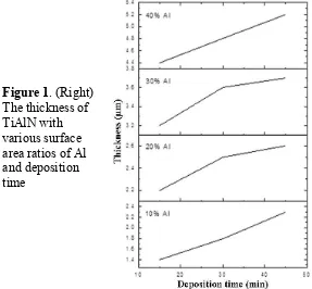
time. The increase in thickness is attributed to the composition of TiAlN and also the deposition time. As the deposition time become longer, it increases the growth time of TiAlN layer on the substrate.
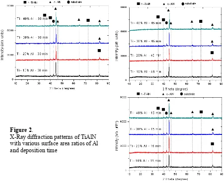
The X-ray diffraction patterns of the TiAlN layer with various surface ratio of Al and deposition time of 15, 30, and 45 minutes are shown in Figure-2. Two primary crystalline phases, cubic structured AlN (c-AlN) and hexagonal structured TiAlN (h-TiAlN) can be identified in all composition. The 10 % Al sample shows the characteristic peak of the (200) AlN phase which slightly shift toward higher 2θ value due to the addition of Al surface ratio on the Ti target. This may indicate a change in the arrangement of atoms in the AlN crystal. According to Bragg’s Law, the higher value of diffraction peak will make the interplanar spacing (d) become much smaller. This can be caused by the stress release in the crystal that is characterized by impairment of micro strain in the crystal.
Figure 2.
X-Ray diffraction patterns of TiAlN with various surface area ratios of Al and deposition time
It is observed that all the diffraction peaks of TiAlN are shifted to higher 2θ angles when the Al percentage is increased, as indicated in Figure-1. This implies that the lattice spacing of former TiN cell is decreased with increasing aluminum content due to the substitution of titanium atoms with aluminum atoms in TiN cell. In general the interstitial site should be large enough to accommodate the interstitial atom, otherwise the presence of the interstitial atom will expand the metalhost lattice to the point where metal-metal interactions become weak and the structure will lose its stability [11].
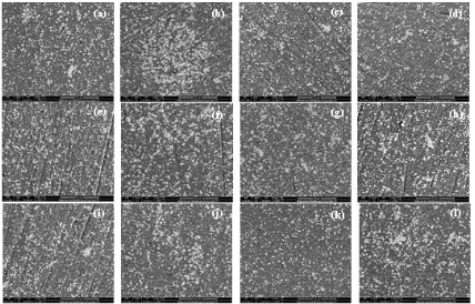
In Figure 3 we can see SEM images of TiAlN thin layer surface morphology, magnified 2000 times. It is observed that the substrate is not fully covered by TiAlN layer with only ~70% areas are covered. Since the distance of substrate material and sputtering target was too close when the sputtering process took place, it caused the sputtered atoms spread out wide and not focused on the substrate surface. However, it is also identified that the increase of deposition time may increase the coverage area of the TiAlN layer.
Figure 3. SEM images of the TiAlN surface with various surface area ratios of Al (a) 10 % Al; 15 min, (b) 20 % Al; 15 min, (c) 30 % Al; 15 min, (d) 40 % Al; 15 min (e) 10 % Al; 30 min, (f) 20 % Al; 30 min, (g) 30 % Al; 30 min, (h) 40 % Al; 30 min (i) 10 % Al; 45 min, (j) 20 % Al; 45 min, (k) 30 % Al; 45 min, (l) 40 % Al; 45 min
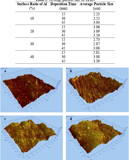
layer. The decline in surface roughness from 11.75 nm to 10.8 nm is observed when increased deposition time from 15 minutes to 45 minutes. The same thing occurs in 40 % Al, where in the deposition time of 15 minutes produces a layer with 12.8 nm surface roughness and then slightly decreases to 12.6 nm with increasing the deposition time to 45 minutes.
CONCLUSION
TiAlN thin layer were deposited on HSS AISI M41 by radio frequency sputtering. A mosaic target with various surface area ratios of Al to Ti obtained by put Al disks on the Ti target. This provides an easy and handy approach to fabrication of compound targets.
Increasing aluminum area on the sputtering target, produces TiAlN layer with a rich content of Al due to the sputtering yield of Al that much higher than Ti. While the deposition time does not significantly impacts the TiAlN composition.
The thickness of TiAlN layer varies from 1.4 µm to 5.2 µm. The increase in thickness is attributed to the composition of TiAlN and also the deposition time. As the deposition time become longer, it increases the growth time of TiAlN layer on the substrate.
The structure of the TiAlN layers was identified as a multiphase consist of cubic structure AlN and hexagonal TiAlN. With the addition of Al, the 2θ angle slightly shifts toward higher 2θ value. Which is caused by the stress is released in the crystal that is characterized by impairment of micro strain in the crystal.
TiAlN layer consists of a round and smooth micro particles. Increasing Al percentage affects the particle size to become much larger particles due to the amount of AlN phase that grow in TiAlN layer.
A 10% Al with the deposition time of 45 minutes has a finest surface roughness of 10.8 nm. Increasing Al surface area ratios affect the surface topography of TiAlN layer to become much denser. While increasing deposition time affect the homogeneity of the TiAlN particles on the substrate.
ACKNOWLEDGMENT
This research is supported by Department of Materials and Metallurgical Engineering, Institut Teknologi Sepuluh Nopember (ITS) Surabaya. The authors are also thankful to Pusat Sains dan Teknologi Akselerator Badan Tenaga Nuklir Nasional (PSTA-BATAN) for providing Radio Frequency Sputtering unit that used in this research and other facilities support.
REFERENCES
[1] Bouzakis, K. D., Bouzakis, E., Kombogiannis, S., Paraskevopoulou, R., Skordaris, G., Makrimallakis, S., Katirtzoglou, G., Pappa, M., Gerardis, S., M’Saoubi, R., Andersson, J.M., Surf. Coat. Tech., 2013, 237: 379-389.
[8] Garcia-Gonzalez, L., Garnica-Romo, M. G., Hernandez-Torres, J., Espinoza-Beltran, F.
J., Braz. J. Chem. Eng., 2007, 24(2): 249-257.
[9] Tanaka, Y., Gur, T. M., Kelly, M., Hogstrom, S. B., Ikeda, T., Thin Solid Films, 1993, 228: 238-241.