SOFTWARE TESTING
AND QUALITY
ASSURANCE
Theory and Practice
KSHIRASAGAR NAIK
Department of Electrical and Computer Engineering University of Waterloo, Waterloo
PRIYADARSHI TRIPATHY
NEC Laboratories America, Inc.
SOFTWARE TESTING
AND QUALITY
SOFTWARE TESTING
AND QUALITY
ASSURANCE
Theory and Practice
KSHIRASAGAR NAIK
Department of Electrical and Computer Engineering University of Waterloo, Waterloo
PRIYADARSHI TRIPATHY
NEC Laboratories America, Inc.
Published by John Wiley & Sons, Inc., Hoboken, New Jersey Published simultaneously in Canada
No part of this publication may be reproduced, stored in a retrieval system, or transmitted in any form or by any means, electronic, mechanical, photocopying, recording, scanning, or otherwise, except as permitted under Section 107 or 108 of the 1976 United States Copyright Act, without either the prior written permission of the Publisher, or authorization through payment of the appropriate per-copy fee to the Copyright Clearance Center, Inc., 222 Rosewood Drive, Danvers, MA 01923, (978) 750-8400, fax (978) 750-4470, or on the web at www.copyright.com. Requests to the Publisher for permission should be addressed to the Permissions Department, John Wiley & Sons, Inc., 111 River Street, Hoboken, NJ 07030, (201) 748-6011, fax (201) 748-6008, or online at
http://www.wiley.com/go/permission.
Limit of Liability/Disclaimer of Warranty: While the publisher and author have used their best efforts in preparing this book, they make no representations or warranties with respect to the accuracy or completeness of the contents of this book and specifically disclaim any implied warranties of merchantability or fitness for a particular purpose. No warranty may be created or extended by sales representatives or written sales materials. The advice and strategies contained herein may not be suitable for your situation. You should consult with a professional where appropriate. Neither the publisher nor author shall be liable for any loss of profit or any other commercial damages, including but not limited to special, incidental, consequential, or other damages.
For general information on our other products and services or for technical support, please contact our Customer Care Department within the United States at (800) 762-2974, outside the United States at (317) 572-3993 or fax (317) 572-4002.
Wiley also publishes its books in a variety of electronic formats. Some content that appears in print may not be available in electronic formats. For more information about Wiley products, visit our web site at www.wiley.com.
Library of Congress Cataloging-in-Publication Data:
Naik, Kshirasagar, 1959–
Software testing and quality assurance / Kshirasagar Naik and Priyadarshi Tripathy. p. cm.
Includes bibliographical references and index. ISBN 978-0-471-78911-6 (cloth)
1. Computer software—Testing. 2. Computer software—Quality control. I. Tripathy, Piyu, 1958–II. Title.
QA76.76.T48N35 2008 005.14—dc22
2008008331
Printed in the United States of America
CONTENTS
Preface xvii
List of Figures xxi
List of Tables xxvii
CHAPTER 1 BASIC CONCEPTS AND PRELIMINARIES 1
1.1 Quality Revolution 1
1.2 Software Quality 5
1.3 Role of Testing 7
1.4 Verification and Validation 7
1.5 Failure, Error, Fault, and Defect 9
1.6 Notion of Software Reliability 10
1.7 Objectives of Testing 10
1.8 What Is a Test Case? 11
1.9 Expected Outcome 12
1.10 Concept ofCompleteTesting 13
1.11 Central Issue in Testing 13
1.12 Testing Activities 14
1.13 Test Levels 16
1.14 Sources of Information for Test Case Selection 18
1.15 White-Box and Black-Box Testing 20
1.16 Test Planning and Design 21
1.17 Monitoring and Measuring Test Execution 22
1.18 Test Tools and Automation 24
1.19 Test Team Organization and Management 26
1.20 Outline of Book 27
References 28
Exercises 30
CHAPTER 2 THEORY OF PROGRAM TESTING 31
2.1 Basic Concepts in Testing Theory 31
2.2 Theory of Goodenough and Gerhart 32
2.2.1 Fundamental Concepts 32
2.2.2 Theory of Testing 34
2.2.3 Program Errors 34
2.2.4 Conditions for Reliability 36
2.2.5 Drawbacks of Theory 37
2.3 Theory of Weyuker and Ostrand 37
2.4 Theory of Gourlay 39
2.4.1 Few Definitions 40
2.4.2 Power of Test Methods 42
2.5 Adequacy of Testing 42
2.6 Limitations of Testing 45
2.7 Summary 46
Literature Review 47
References 48
Exercises 49
CHAPTER 3 UNIT TESTING 51
3.1 Concept of Unit Testing 51
3.2 Static Unit Testing 53
3.3 Defect Prevention 60
3.4 Dynamic Unit Testing 62
3.5 Mutation Testing 65
3.6 Debugging 68
3.7 Unit Testing in eXtreme Programming 71
3.8 JUnit: Framework for Unit Testing 73
3.9 Tools for Unit Testing 76
3.10 Summary 81
Literature Review 82
References 84
Exercises 86
CHAPTER 4 CONTROL FLOW TESTING 88
4.1 Basic Idea 88
4.2 Outline of Control Flow Testing 89
4.3 Control Flow Graph 90
4.4 Paths in a Control Flow Graph 93
4.5 Path Selection Criteria 94
4.5.1 All-Path Coverage Criterion 96
4.5.2 Statement Coverage Criterion 97
4.5.3 Branch Coverage Criterion 98
4.5.4 Predicate Coverage Criterion 100
4.6 Generating Test Input 101
4.7 Examples of Test Data Selection 106
4.8 Containing Infeasible Paths 107
4.9 Summary 108
Literature Review 109
References 110
Exercises 111
CHAPTER 5 DATA FLOW TESTING 112
5.1 General Idea 112
5.2 Data Flow Anomaly 113
5.3 Overview of Dynamic Data Flow Testing 115
CONTENTS ix
5.5 Data Flow Terms 119
5.6 Data Flow Testing Criteria 121
5.7 Comparison of Data Flow Test Selection Criteria 124
5.8 Feasible Paths and Test Selection Criteria 125
5.9 Comparison of Testing Techniques 126
5.10 Summary 128
Literature Review 129
References 131
Exercises 132
CHAPTER 6 DOMAIN TESTING 135
6.1 Domain Error 135
6.2 Testing for Domain Errors 137
6.3 Sources of Domains 138
6.4 Types of Domain Errors 141
6.5 ON and OFF Points 144
6.6 Test Selection Criterion 146
6.7 Summary 154
Literature Review 155
References 156
Exercises 156
CHAPTER 7 SYSTEM INTEGRATION TESTING 158
7.1 Concept of Integration Testing 158
7.2 Different Types of Interfaces and Interface Errors 159
7.3 Granularity of System Integration Testing 163
7.4 System Integration Techniques 164
7.4.1 Incremental 164
7.4.2 Top Down 167
7.4.3 Bottom Up 171
7.4.4 Sandwich and Big Bang 173
7.5 Software and Hardware Integration 174
7.5.1 Hardware Design Verification Tests 174
7.5.2 Hardware and Software Compatibility Matrix 177
7.6 Test Plan for System Integration 180
7.7 Off-the-Shelf Component Integration 184
7.7.1 Off-the-Shelf Component Testing 185
7.7.2 Built-in Testing 186
7.8 Summary 187
Literature Review 188
References 189
Exercises 190
CHAPTER 8 SYSTEM TEST CATEGORIES 192
8.1 Taxonomy of System Tests 192
8.2 Basic Tests 194
8.2.1 Boot Tests 194
8.2.3 Light Emitting Diode Tests 195
8.2.4 Diagnostic Tests 195
8.2.5 Command Line Interface Tests 196
8.3 Functionality Tests 196
8.3.1 Communication Systems Tests 196
8.3.2 Module Tests 197
8.3.3 Logging and Tracing Tests 198
8.3.4 Element Management Systems Tests 198
8.3.5 Management Information Base Tests 202
8.3.6 Graphical User Interface Tests 202
8.3.7 Security Tests 203
8.3.8 Feature Tests 204
8.4 Robustness Tests 204
8.4.1 Boundary Value Tests 205
8.4.2 Power Cycling Tests 206
8.4.3 On-Line Insertion and Removal Tests 206
8.4.4 High-Availability Tests 206
8.4.5 Degraded Node Tests 207
8.5 Interoperability Tests 208
8.6 Performance Tests 209
8.7 Scalability Tests 210
8.8 Stress Tests 211
8.9 Load and Stability Tests 213
8.10 Reliability Tests 214
8.11 Regression Tests 214
8.12 Documentation Tests 215
8.13 Regulatory Tests 216
8.14 Summary 218
Literature Review 219
References 220
Exercises 221
CHAPTER 9 FUNCTIONAL TESTING 222
9.1 Functional Testing Concepts of Howden 222
9.1.1 Different Types of Variables 224
9.1.2 Test Vector 230
9.1.3 Testing a Function in Context 231
9.2 Complexity of Applying Functional Testing 232
9.3 Pairwise Testing 235
9.3.1 Orthogonal Array 236
9.3.2 In Parameter Order 240
9.4 Equivalence Class Partitioning 244
9.5 Boundary Value Analysis 246
9.6 Decision Tables 248
9.7 Random Testing 252
9.8 Error Guessing 255
9.9 Category Partition 256
CONTENTS xi
Literature Review 260
References 261
Exercises 262
CHAPTER 10 TEST GENERATION FROM FSM MODELS 265
10.1 State-Oriented Model 265
10.2 Points of Control and Observation 269
10.3 Finite-State Machine 270
10.4 Test Generation from an FSM 273
10.5 Transition Tour Method 273
10.6 Testing with State Verification 277
10.7 Unique Input–Output Sequence 279
10.8 Distinguishing Sequence 284
10.9 Characterizing Sequence 287
10.10 Test Architectures 291
10.10.1 Local Architecture 292
10.10.2 Distributed Architecture 293
10.10.3 Coordinated Architecture 294
10.10.4 Remote Architecture 295
10.11 Testing and Test Control Notation Version 3 (TTCN-3) 295
10.11.1 Module 296
10.11.2 Data Declarations 296
10.11.3 Ports and Components 298
10.11.4 Test Case Verdicts 299
10.11.5 Test Case 300
10.12 Extended FSMs 302
10.13 Test Generation from EFSM Models 307
10.14 Additional Coverage Criteria for System Testing 313
10.15 Summary 315
Literature Review 316
References 317
Exercises 318
CHAPTER 11 SYSTEM TEST DESIGN 321
11.1 Test Design Factors 321
11.2 Requirement Identification 322
11.3 Characteristics of Testable Requirements 331
11.4 Test Objective Identification 334
11.5 Example 335
11.6 Modeling a Test Design Process 345
11.7 Modeling Test Results 347
11.8 Test Design Preparedness Metrics 349
11.9 Test Case Design Effectiveness 350
11.10 Summary 351
Literature Review 351
References 353
CHAPTER 12 SYSTEM TEST PLANNING AND AUTOMATION 355
12.1 Structure of a System Test Plan 355
12.2 Introduction and Feature Description 356
12.3 Assumptions 357
12.4 Test Approach 357
12.5 Test Suite Structure 358
12.6 Test Environment 358
12.7 Test Execution Strategy 361
12.7.1 Multicycle System Test Strategy 362
12.7.2 Characterization of Test Cycles 362
12.7.3 Preparing for First Test Cycle 366
12.7.4 Selecting Test Cases for Final Test Cycle 369
12.7.5 Prioritization of Test Cases 371
12.7.6 Details of Three Test Cycles 372
12.8 Test Effort Estimation 377
12.8.1 Number of Test Cases 378
12.8.2 Test Case Creation Effort 384
12.8.3 Test Case Execution Effort 385
12.9 Scheduling and Test Milestones 387
12.10 System Test Automation 391
12.11 Evaluation and Selection of Test Automation Tools 392
12.12 Test Selection Guidelines for Automation 395
12.13 Characteristics of Automated Test Cases 397
12.14 Structure of an Automated Test Case 399
12.15 Test Automation Infrastructure 400
12.16 Summary 402
Literature Review 403
References 405
Exercises 406
CHAPTER 13 SYSTEM TEST EXECUTION 408
13.1 Basic Ideas 408
13.2 Modeling Defects 409
13.3 Preparedness to Start System Testing 415
13.4 Metrics for Tracking System Test 419
13.4.1 Metrics for Monitoring Test Execution 420
13.4.2 Test Execution Metric Examples 420
13.4.3 Metrics for Monitoring Defect Reports 423
13.4.4 Defect Report Metric Examples 425
13.5 Orthogonal Defect Classification 428
13.6 Defect Causal Analysis 431
13.7 Beta Testing 435
13.8 First Customer Shipment 437
13.9 System Test Report 438
13.10 Product Sustaining 439
13.11 Measuring Test Effectiveness 441
13.12 Summary 445
CONTENTS xiii
References 447
Exercises 448
CHAPTER 14 ACCEPTANCE TESTING 450
14.1 Types of Acceptance Testing 450
14.2 Acceptance Criteria 451
14.3 Selection of Acceptance Criteria 461
14.4 Acceptance Test Plan 461
14.5 Acceptance Test Execution 463
14.6 Acceptance Test Report 464
14.7 Acceptance Testing in eXtreme Programming 466
14.8 Summary 467
Literature Review 468
References 468
Exercises 469
CHAPTER 15 SOFTWARE RELIABILITY 471
15.1 What Is Reliability? 471
15.1.1 Fault and Failure 472
15.1.2 Time 473
15.1.3 Time Interval between Failures 474
15.1.4 Counting Failures in Periodic Intervals 475
15.1.5 Failure Intensity 476
15.2 Definitions of Software Reliability 477
15.2.1 First Definition of Software Reliability 477
15.2.2 Second Definition of Software Reliability 478
15.2.3 Comparing the Definitions of Software Reliability 479
15.3 Factors Influencing Software Reliability 479
15.4 Applications of Software Reliability 481
15.4.1 Comparison of Software Engineering Technologies 481
15.4.2 Measuring the Progress of System Testing 481
15.4.3 Controlling the System in Operation 482
15.4.4 Better Insight into Software Development Process 482
15.5 Operational Profiles 482
15.5.1 Operation 483
15.5.2 Representation of Operational Profile 483
15.6 Reliability Models 486
15.7 Summary 491
Literature Review 492
References 494
Exercises 494
CHAPTER 16 TEST TEAM ORGANIZATION 496
16.1 Test Groups 496
16.1.1 Integration Test Group 496
16.1.2 System Test Group 497
16.2 Software Quality Assurance Group 499
16.4 Effective Staffing of Test Engineers 501
16.5 Recruiting Test Engineers 504
16.5.1 Job Requisition 504
16.5.2 Job Profiling 505
16.5.3 Screening Resumes 505
16.5.4 Coordinating an Interview Team 506
16.5.5 Interviewing 507
16.5.6 Making a Decision 511
16.6 Retaining Test Engineers 511
16.6.1 Career Path 511
16.6.2 Training 512
16.6.3 Reward System 513
16.7 Team Building 513
16.7.1 Expectations 513
16.7.2 Consistency 514
16.7.3 Information Sharing 514
16.7.4 Standardization 514
16.7.5 Test Environments 514
16.7.6 Recognitions 515
16.8 Summary 515
Literature Review 516
References 516
Exercises 517
CHAPTER 17 SOFTWARE QUALITY 519
17.1 Five Views of Software Quality 519
17.2 McCall’s Quality Factors and Criteria 523
17.2.1 Quality Factors 523
17.2.2 Quality Criteria 527
17.2.3 Relationship between Quality Factors and Criteria 527
17.2.4 Quality Metrics 530
17.3 ISO 9126 Quality Characteristics 530
17.4 ISO 9000:2000 Software Quality Standard 534
17.4.1 ISO 9000:2000 Fundamentals 535
17.4.2 ISO 9001:2000 Requirements 537
17.5 Summary 542
Literature Review 544
References 544
Exercises 545
CHAPTER 18 MATURITY MODELS 546
18.1 Basic Idea in Software Process 546
18.2 Capability Maturity Model 548
18.2.1 CMM Architecture 549
18.2.2 Five Levels of Maturity and Key Process Areas 550
18.2.3 Common Features of Key Practices 553
18.2.4 Application of CMM 553
CONTENTS xv
18.3 Test Process Improvement 555
18.4 Testing Maturity Model 568
18.5 Summary 578
Literature Review 578
References 579
Exercises 579
GLOSSARY 581
PREFACE
karmany eva dhikaras te; ma phalesu kadachana; ma karmaphalahetur bhur; ma te sango stv akarmani.
Your right is to work only; but never to the fruits thereof; may you not be motivated by the fruits of actions; nor let your attachment to be towards inaction. — Bhagavad Gita
We have been witnessing tremendous growth in the software industry over the past 25 years. Software applications have proliferated from the original data processing and scientific computing domains into our daily lives in such a way that we do not realize that some kind of software executes when we do even something ordinary, such as making a phone call, starting a car, turning on a microwave oven, and making a debit card payment. The processes for producing software must meet two broad challenges. First, the processes must produce low-cost software in a short time so that corporations can stay competitive. Second, the processes must produce usable, dependable, and safe software; these attributes are commonly known as quality attributes. Software quality impacts a number of important factors in our daily lives, such as economy, personal and national security, health, and safety.
Twenty-five years ago, testing accounted for about 50% of the total time and more than 50% of the total money expended in a software development project—and, the same is still true today. Those days the software industry was a much smaller one, and academia offered a single, comprehensive course entitled
Software Engineering to educate undergraduate students in the nuts and bolts of software development. Although software testing has been a part of the classical software engineering literature for decades, the subject is seldom incorporated into the mainstream undergraduate curriculum. A few universities have started offering an option in software engineering comprising three specialized courses, namely,
Requirements Specification,Software Design, andTesting and Quality Assurance. In addition, some universities have introduced full undergraduate and graduate degree programs in software engineering.
Considering the impact of software quality, or the lack thereof, we observe that software testing education has not received its due place. Ideally, research should lead to the development of tools and methodologies to produce low-cost, high-quality software, and students should be educated in the testing fundamentals. In other words, software testing research should not be solely academic in nature but must strive to be practical for industry consumers. However, in practice, there
is a large gap between the testing skills needed in the industry and what are taught and researched in the universities.
Our goal is to provide the students and the teachers with a set of well-rounded educational materials covering the fundamental developments in testing theory and common testing practices in the industry. We intend to provide the students with the “big picture” of testing and quality assurance, because software quality concepts are quite broad. There are different kinds of software systems with their own intricate characteristics. We have not tried to specifically address their testing challenges. Instead, we have presented testing theory and practice as broad stepping stones which will enable the students to understand and develop testing practices for more complex systems.
We decided to write this book based on our teaching and industrial experi-ences in software testing and quality assurance. For the past 15 years, Sagar has been teaching software engineering and software testing on a regular basis, whereas Piyu has been performing hands-on testing and managing test groups for testing routers, switches, wireless data networks, storage networks, and intrusion preven-tion appliances. Our experiences have helped us in selecting and structuring the contents of this book to make it suitable as a textbook.
Who Should Read This Book?
We have written this book to introduce students and software professionals to the fundamental ideas in testing theory, testing techniques, testing practices, and quality assurance. Undergraduate students in software engineering, computer science, and computer engineering with no prior experience in the software industry will be introduced to the subject matter in a step-by-step manner. Practitioners too will benefit from the structured presentation and comprehensive nature of the materials. Graduate students can use the book as a reference resource. After reading the whole book, the reader will have a thorough understanding of the following topics:
• Fundamentals of testing theory and concepts
• Practices that support the production of quality software • Software testing techniques
• Life-cycle models of requirements, defects, test cases, and test results • Process models for unit, integration, system, and acceptance testing • Building test teams, including recruiting and retaining test engineers • Quality models, capability maturity model, testing maturity model, and test
process improvement model
How Should This Book be Read?
PREFACE xix
quality questions to a later part of the book. It is difficult to intelligently discuss for beginners what software qualitymeans until one has a firm sense of what software testing does. However, practitioners with much testing experience can jump to Chapter 17, entitled “Software Quality,” immediately after Chapter 1.
There are three different ways to read this book depending upon someone’s interest. First, those who are exclusively interested in software testing concepts and want to apply the ideas should read Chapter 1 (“Basic Concepts and Preliminaries”), Chapter 3 (“Unit Testing”), Chapter 7 (“System Integration Testing”), and Chapters 8–14, related to system-level testing. Second, test managers interested in improving the test effectiveness of their teams can read Chapters 1, 3, 7, 8–14, 16 (“Test Team Organization”), 17 (“Software Quality”), and 18 (“Maturity Models”). Third, beginners should read the book from cover to cover.
Notes for Instructors
The book can be used as a text in an introductory course in software testing and quality assurance. One of the authors used the contents of this book in an under-graduate course entitled Software Testing and Quality Assurance for several years at the University of Waterloo. An introductory course in software testing can cover selected sections from most of the chapters except Chapter 16. For a course with more emphasis on testing techniques than on processes, we recommend to choose Chapters 1 (“Basic Concepts and Preliminaries”) to 15 (“Software Reliability”). When used as a supplementary text in a software engineering course, selected por-tions from the following chapters can help students imbibe the essential concepts in software testing:
• Chapter 1: Basic Concepts and Preliminaries • Chapter 3: Unit Testing
• Chapter 7: System Integration Testing • Chapter 8: System Test Category • Chapter 14: Acceptance Testing
Supplementary materials for instructors are available at the following Wiley web-site: http:/www.wiley.com/sagar.
Acknowledgments
all his effort and encouragement. The second author, Piyu Tripathy, would like to thank his former colleagues at Nortel Networks, Cisco Systems, and Airvana Inc., and present colleagues at NEC Laboratories America.
Finally, the support of our parents, parents-in-law, and partners deserve a special mention. I, Piyu Tripathy, would like to thank my dear wife Leena, who has taken many household and family duties off my hands to give me time that I needed to write this book. And I, Sagar Naik, would like to thank my loving wife Alaka for her invaluable support and for always being there for me. I would also like to thank my charming daughters, Monisha and Sameeksha, and exciting son, Siddharth, for their understanding while I am writing this book. I am grateful to my elder brother, Gajapati Naik, for all his support. We are very pleased that now we have more time for our families and friends.
Kshirasagar Naik
University of Waterloo Waterloo
Priyadarshi Tripathy
LIST OF FIGURES
1.1 Shewhart cycle 2
1.2 Ishikawa diagram 4
1.3 Examples of basic test cases 11
1.4 Example of a test case with a sequence of<input, expected outcome> 12
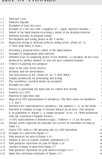
1.5 Subset of the input domain exercising a subset of the program behavior 14
1.6 Different activities in program testing 14
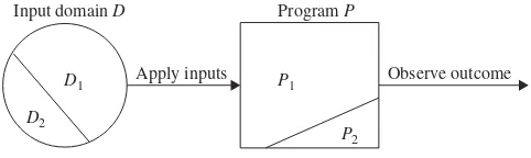
1.7 Development and testing phases in the V model 16
1.8 Regression testing at different software testing levels. (From ref. 41.
©2005 John Wiley & Sons.) 17
2.1 Executing a program with a subset of the input domain 32
2.2 Example of inappropriate path selection 35
2.3 Different ways of comparing power of test methods: (a) produces all test cases produced by another method; (b) test sets have common elements. 43
2.4 Context of applying test adequacy 44
3.1 Steps in the code review process 55
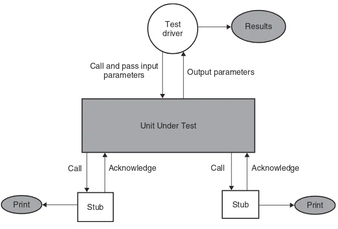
3.2 Dynamic unit test environment 63
3.3 Test-first process in XP. (From ref. 24.©2005 IEEE.) 72
3.4 Sample pseudocode for performing unit testing 73
3.5 The assertTrue() assertion throws an exception 75
3.6 Example test suite 76
4.1 Process of generating test input data for control flow testing 90
4.2 Symbols in a CFG 91
4.3 Function to open three files 91
4.4 High-level CFG representation of openfiles(). The three nodes are numbered
1, 2, and 3. 92
4.5 Detailed CFG representation of openfiles(). The numbers 1–21 are the nodes 93
4.6 Function to compute average of selected integers in an array. This program is an adaptation of “Figure 2. A sample program” in ref. 10. (With permission
from the Australian Computer Society.) 94
4.7 A CFG representation of ReturnAverage(). Numbers 1–13 are the nodes. 95
4.8 Dashed arrows represent the branches not covered by statement covering in
Table 4.4 99
4.9 Partial CFG with (a) OR operation and (b) AND operations 100
4.10 Example of a path from Figure 4.7 102
4.11 Path predicate for path in Figure 4.10 102
4.12 Method in Java to explain symbolic substitution [11] 103
4.13 Path predicate expression for path in Figure 4.10 105
4.14 Another example of path from Figure 4.7 105
4.15 Path predicate expression for path shown in Figure 4.14 106
4.16 Input data satisfying constraints of Figure 4.13 106
4.17 Binary search routine 111
5.1 Sequence of computations showing data flow anomaly 113
5.2 State transition diagram of a program variable. (From ref. 2.©1979 IEEE.) 115
5.3 Definition and uses of variables 117
5.4 Data flow graph of ReturnAverage() example 118
5.5 Relationship among DF (data flow) testing criteria. (From ref. 4.©1988
IEEE.) 125
5.6 Relationship among FDF (feasible data flow) testing criteria.
(From ref. 4.©1988 IEEE.) 127
5.7 Limitation of different fault detection techniques 128
5.8 Binary search routine 133
5.9 Modified binary search routine 133
6.1 Illustration of the concept of program domains 137
6.2 A function to explain program domains 139
6.3 Control flow graph representation of the function in Figure 6.2 139
6.4 Domains obtained from interpreted predicates in Figure 6.3 140
6.5 Predicates defining the TT domain in Figure 6.4 141
6.6 ON and OFF points 146
6.7 Boundary shift resulting in reduced domain (closed inequality) 147
6.8 Boundary shift resulting in enlarged domain (closed inequality) 149
6.9 Tilted boundary (closed inequality) 149
6.10 Closure error (closed inequality) 150
6.11 Boundary shift resulting in reduced domain (open inequality) 151
6.12 Boundary shift resulting in enlarged domain (open inequality) 152
6.13 Tilted boundary (open inequality) 153
6.14 Closure error (open inequality) 153
6.15 Equality border 154
6.16 DomainsD1,D2 andD3 157
7.1 Module hierarchy with three levels and seven modules 168
7.2 Top-down integration of modules A and B 169
7.3 Top-down integration of modules A, B, and D 169
7.4 Top-down integration of modules A, B, D, and C 169
7.5 Top-down integration of modules A, B, C, D, and E 170
7.6 Top-down integration of modules A, B, C, D, E, and F 170
7.7 Top-down integration of modules A, B, C, D, E, F and G 170
7.8 Bottom-up integration of modules E, F, and G 171
7.9 Bottom-up integration of modules B, C, and D with E, F, and G 172
7.10 Bottom-up integration of module A with all others 172
7.11 Hardware ECO process 179
7.12 Software ECO process 180
7.13 Module hierarchy of software system 190
8.1 Types of system tests 193
8.2 Types of basic tests 194
8.3 Types of functionality tests 197
8.4 Types of robustness tests 205
8.5 Typical 1xEV-DO radio access network. (Courtesy of Airvana, Inc.) 206
9.1 Frequency selection box of Bluetooth specification 224
LIST OF FIGURES xxiii
9.3 Functionally related variables 231
9.4 Function in context 232
9.5 (a) Obtaining output values from an input vector and (b) obtaining an input
vector from an output value in functional testing 233
9.6 Functional testing in general 234
9.7 SystemS with three input variables 235
9.8 (a) Too many test inputs; (b) one input selected from each subdomain 244
9.9 Gold standard oracle 253
9.10 Parametric oracle 253
9.11 Statistical oracle 254
10.1 Spectrum of software systems 266
10.2 Data-dominated systems 266
10.3 Control-dominated systems 267
10.4 FSM model of dual-boot laptop computer 267
10.5 Interactions between system and its environment modeled as FSM 268
10.6 PCOs on a telephone 269
10.7 FSM model of a PBX 270
10.8 FSM model of PBX 271
10.9 Interaction of test sequence with SUT 274
10.10 Derived test case from transition tour 275
10.11 Conceptual model of test case with state verification 278
10.12 Finite-state machineG1(From ref. 5.©1997 IEEE.) 281
10.13 UIO tree forG1in Figure 10.12. (From ref. 5.©1997 IEEE.) 282
10.14 Identification of UIO sequences on UIO tree of Figure 10.13 283
10.15 Finite-state machineG2 286
10.16 Distinguishing sequence tree forG2in Figure 10.15 286
10.17 FSM that does not possess distinguishing sequence. (From ref. 11.©1994
IEEE.) 287
10.18 DS tree for FSM (Figure 10.17) 288
10.19 Abstraction ofN-entity in OSI reference architecture 291
10.20 Abstract local test architecture 292
10.21 Abstract external test architecture 292
10.22 Local architecture 293
10.23 Distributed architecture 293
10.24 Coordinated architecture 294
10.25 Remote architecture 295
10.26 Structure of module in TTCN-3 297
10.27 Definitions of two subtypes 297
10.28 Parameterized template for constructing message to be sent 298
10.29 Parameterized template for constructing message to be received 298
10.30 Testing (a) square-root function (SRF) calculator and (b) port between
tester and SRF calculator 299
10.31 Defining port type 300
10.32 Associating port with component 300
10.33 Test case for testing SRF calculator 301
10.34 Executing test case 302
10.35 Comparison of state transitions of FSM and EFSM 303
10.36 Controlled access to a door 304
10.38 Door control behavior specification 306
10.39 Door control behavior specification 307
10.40 Transition tour from door control system of Figures 10.38 and 10.39 309
10.41 Testing door control system 309
10.42 Output and input behavior obtained from transition tour of Figure 10.40 310
10.43 Test behavior obtained by refining if part in Figure 10.42 310
10.44 Test behavior that can receive unexpected events (derived from Figure 10.43) 311
10.45 Core behavior of test case for testing door control system (derived from
Figure 10.44) 312
10.46 User interface of ATM 314
10.47 Binding of buttons with user options 314
10.48 Binding of buttons with cash amount 315
10.49 FSM G 318
10.50 FSM H 318
10.51 FSM K 319
10.52 Nondeterministic FSM 319
11.1 State transition diagram of requirement 323
11.2 Test suite structure 336
11.3 Service interworking between FR and ATM services 337
11.4 Transformation of FR to ATM cell 338
11.5 FrAtm test suite structure 342
11.6 State transition diagram of a test case 345
11.7 State transition diagram of test case result 349
12.1 Concept of cycle-based test execution strategy 363
12.2 Gantt chart for FR–ATM service interworking test project 390
12.3 Broad criteria of test automation tool evaluation 393
12.4 Test selection guideline for automation 396
12.5 Characteristics of automated test cases 397
12.6 Six major steps in automated test case 399
12.7 Components of a automation infrastructure 401
13.1 State transition diagram representation of life cycle of defect 409
13.2 Projected execution of test cases on weekly basis in cumulative chart form 417
13.3 PAE metric of Bazooka (PE: projected execution; AE: actually executed)
project 421
13.4 Pareto diagram for defect distribution shown in Table 13.12 431
13.5 Cause–effect diagram for DCA 434
15.1 Relationship between MTTR, MTTF, and MTBF 475
15.2 Graphical representation of operational profile of library information system 484
15.3 Failure intensityλas function of cumulative failureμ(λ0=9 failures
per unit time,ν0=500 failures,θ=0.0075) 488
15.4 Failure intensityλas function of execution timeτ(λ0=9 failures
per unit time,ν0=500 failures,θ=0.0075) 490
15.5 Cumulative failureμas function of execution timeτ (λ0=9 failures per unit
time,ν0=500 failures,θ=0.0075) 490
16.1 Structure of test groups 498
16.2 Structure of software quality assurance group 499
16.3 System test team hierarchy 500
LIST OF FIGURES xxv
16.5 System test organization as part of development 518
17.1 Relation between quality factors and quality criteria [6] 528
17.2 ISO 9126 sample quality model refines standard’s features into
subcharacteristics. (From ref. 4.©1996 IEEE.) 532
18.1 CMM structure. (From ref. 3.©2005 John Wiley & Sons.) 549
18.2 SW-CMM maturity levels. (From ref. 3©2005 John Wiley & Sons.) 550
LIST OF TABLES
3.1 Hierarchy of System Documents 56
3.2 Code Review Checklist 58
3.3 McCabe Complexity Measure 79
4.1 Examples of Path in CFG of Figure 4.7 95
4.2 Input Domain of openfiles() 97
4.3 Inputs and Paths in openfiles() 97
4.4 Paths for Statement Coverage of CFG of Figure 4.7 98
4.5 Paths for Branch Coverage of CFG of Figure 4.7 99
4.6 Two Cases for Complete Statement and Branch Coverage of CFG of
Figure 4.9a 101
4.7 Interpretation of Path Predicate of Path in Figure 4.10 104
4.8 Interpretation of Path Predicate of Path in Figure 4.14 105
4.9 Test Data for Statement and Branch Coverage 106
5.1 Def() and c-use() Sets of Nodes in Figure 5.4 120
5.2 Predicates and p-use() Set of Edges in Figure 5.4 121
6.1 Two Interpretations of Second if() Statement in Figure 6.2 140
6.2 Detection of Boundary Shift Resulting in Reduced Domain
(Closed Inequality) 148
6.3 Detection of Boundary Shift Resulting in Enlarged Domain
(Closed Inequality) 149
6.4 Detection of Boundary Tilt (Closed Inequality) 150
6.5 Detection of Closure Error (Closed Inequality) 151
6.6 Detection of Boundary Shift Resulting in Reduced Domain (Open Inequality) 151
6.7 Detection of Boundary Shift Resulting in Enlarged Domain (Open Inequality) 152
6.8 Detection of Boundary Tilt (Open Inequality) 153
6.9 Detection of Closure Error (Open Inequality) 154
7.1 Check-in Request Form 166
7.2 Example Software/Hardware Compatibility Matrix 178
7.3 Framework for SIT Plan 181
7.4 Framework for Entry Criteria to Start System Integration 182
7.5 Framework for System Integration Exit Criteria 182
8.1 EMS Functionalities 199
8.2 Regulatory Approval Bodies of Different Countries 217
9.1 Number of Special Values of Inputs to FBS Module of Figure 9.1 230
9.2 Input and Output Domains of Functions ofP in Figure 9.6 234
9.3 Pairwise Test Cases for SystemS 236
9.4 L4(23)Orthogonal Array 236
9.5 Commonly Used Orthogonal Arrays 237
9.6 Various Values That Need to Be Tested in Combinations 238
9.7 L9(34)Orthogonal Array 239
9.8 L9(34)Orthogonal Array after Mapping Factors 239
9.9 Generated Test Cases after Mapping Left-Over Levels 240
9.10 Generated Test Cases to Cover Each Equivalence Class 246
9.11 Decision Table Comprising Set of Conditions and Effects 248
9.12 Pay Calculation Decision Table with Values for Each Rule 250
9.13 Pay Calculation Decision Table after Column Reduction 251
9.14 Decision Table for Payment Calculation 252
10.1 PCOs for Testing Telephone PBX 270
10.2 Set of States in FSM of Figure 10.8 272
10.3 Input and Output Sets in FSM of Figure 10.8 272
10.4 Transition Tours Covering All States in Figure 10.8 276
10.5 State Transitions Not Covered by Transition Tours of Table 10.4 277
10.6 Transition Tours Covering All State Transitions in Figure 10.8 277
10.7 UIO Sequences of Minimal Lengths Obtained from Figure 10.14 284
10.8 Examples of State Blocks 284
10.9 Outputs of FSMG2 in Response to Input Sequence 11 in Different States 287
10.10 Output Sequences Generated by FSM of Figure 10.17 as Response toW1 289
10.11 Output Sequences Generated by FSM of Figure 10.17 as Response toW2 289
10.12 Test Sequences for State Transition (D,A,a/x) of FSM in Figure 10.17 290
11.1 Coverage Matrix [Aij] 322
11.2 Requirement Schema Field Summary 324
11.3 Engineering Change Document Information 329
11.4 Characteristics of Testable Functional Specifications 333
11.5 Mapping of FR QoS Parameters to ATM QoS Parameters 340
11.6 Test Case Schema Summary 346
11.7 Test Suite Schema Summary 348
11.8 Test Result Schema Summary 348
12.1 Outline of System Test Plan 356
12.2 Equipment Needed to be Procured 360
12.3 Entry Criteria for First System Test Cycle 368
12.4 Test Case Failure Counts to Initiate RCA in Test Cycle 1 374
12.5 Test Case Failure Counts to Initiate RCA in Test Cycle 2 375
12.6 Test Effort Estimation for FR–ATM PVC Service Interworking 379
12.7 Form for Computing Unadjusted Function Point 382
12.8 Factors Affecting Development Effort 382
12.9 Empirical Relationship between Function Points and LOC 383
12.10 Guidelines for Manual Test Case Creation Effort 384
12.11 Guidelines for Manual Test Case Execution Effort 386
12.12 Guidelines for Estimation of Effort to Manually Execute Regression
Test Cases 386
12.13 Benefits of Automated Testing 391
13.1 States of Defect Modeled in Figure 13.1 410
13.2 Defect Schema Summary Fields 412
13.3 State Transitions to Five Possible Next States from Open State 413
13.4 Outline of Test Execution Working Document 416
13.5 EST Metric in Week 4 of Bazooka Project 422
LIST OF TABLES xxix
13.7 DAR Metric for Stinger Project 425
13.8 Weekly DRR Status for Stinger Test Project 426
13.9 Weekly OD on Priority Basis for Stinger Test Project 427
13.10 Weekly CD Observed by Different Groups for Stinger Test Project 427
13.11 ARD Metric forBayonet 428
13.12 Sample Test Data of Chainsaw Test Project 430
13.13 Framework for Beta Release Criteria 436
13.14 Structure of Final System Test Report 438
13.15 Scale for Defect Age 443
13.16 Defect Injection versus Discovery on Project Boomerang 443
13.17 Number of Defects Weighted by Defect Age on Project Boomerang 444
13.18 ARD Metric for Test Project 448
13.19 Scale for PhAge 449
14.1 Outline of ATP 462
14.2 ACC Document Information 464
14.3 Structure of Acceptance Test Status Report 465
14.4 Structure of Acceptance Test Summary Report 466
15.1 Example of Operational Profile of Library Information System 484
17.1 McCall’s Quality Factors 524
17.2 Categorization of McCall’s Quality Factors 527
17.3 McCall’s Quality Criteria 529
18.1 Requirements for Different Maturity Levels 564
CHAPTER
1
Basic Concepts and Preliminaries
Software is like entropy. It is difficult to grasp, weighs nothing, and obeys the second law of thermodynamics, i.e., it always increases.
— Norman Ralph Augustine
1.1 QUALITY REVOLUTION
People seek quality in every man-made artifact. Certainly, the concept of quality did not originate with software systems. Rather, the quality concept is likely to be as old as human endeavor to mass produce artifacts and objects of large size. In the past couple of decades a quality revolution, has been spreading fast throughout the world with the explosion of the Internet. Global competition, outsourcing, off-shoring, and increasing customer expectations have brought the concept of quality to the forefront. Developing quality products on tighter schedules is critical for a company to be successful in the new global economy. Traditionally, efforts to improve quality have centered around the end of the product development cycle by emphasizing the detection and correction of defects. On the contrary, the new approach to enhancing quality encompasses all phases of a product development process—from a requirements analysis to the final delivery of the product to the customer. Every step in the development process must be performed to the highest possible standard. An effective quality process must focus on [1]:
• Paying much attention to customer’s requirements • Making efforts to continuously improve quality
• Integrating measurement processes with product design and development • Pushing the quality concept down to the lowest level of the organization • Developing a system-level perspective with an emphasis on methodology
and process
• Eliminating waste through continuous improvement
Software Testing and Quality Assurance: Theory and Practice, Edited by Kshirasagar Naik and Priyadarshi Tripathy Copyright©2008 John Wiley & Sons, Inc.
A quality movement started in Japan during the 1940s and the 1950s by William Edwards Deming, Joseph M. Juran, and Kaoru Ishikawa. In circa 1947, W. Edwards Deming “visited India as well, then continued on to Japan, where he had been asked to join a statistical mission responsible for planning the 1951 Japanese census” [2], p. 8. During his said visit to Japan, Deming invited statis-ticians for a dinner meeting and told them how important they were and what they could do for Japan [3]. In March 1950, he returned to Japan at the invitation of Managing Director Kenichi Koyanagi of the Union of Japanese Scientists and Engineers (JUSE) to teach a course to Japanese researchers, workers, executives, and engineers on statistical quality control (SQC) methods. Statistical quality con-trol is a discipline based on measurements and statistics. Decisions are made and plans are developed based on the collection and evaluation of actual data in the form of metrics, rather than intuition and experience. The SQC methods use seven basic quality management tools: Pareto analysis, cause-and-effect diagram, flow chart, trend chart, histogram, scatter diagram, and control chart [2].
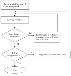
In July 1950, Deming gave an eight-day seminar based on the Shewhart meth-ods of statistical quality control [4, 5] for Japanese engineers and executives. He introduced theplan–do–check–act (PDCA) cycle in the seminar, which he called the Shewhart cycle (Figure 1.1). The Shewhart cycle illustrates the following activ-ity sequence: setting goals, assigning them to measurable milestones, and assessing the progress against those milestones. Deming’s 1950 lecture notes formed the basis for a series of seminars on SQC methods sponsored by the JUSE and provided the criteria for Japan’s famed Deming Prize. Deming’s work has stimulated several dif-ferent kinds of industries, such as those for radios, transistors, cameras, binoculars, sewing machines, and automobiles.
Between circa 1950 and circa 1970, automobile industries in Japan, in par-ticular Toyota Motor Corporation, came up with an innovative principle to com-press the time period from customer order to banking payment, known as the “lean principle.” The objective was to minimize the consumption of resources that added no value to a product. The lean principle has been defined by the National Institute of Standards and Technology (NIST) Manufacturing Extension Partnership program [61] as “a systematic approach to identifying and eliminat-ing waste through continuous improvement, floweliminat-ing the product at the pull of the customer in pursuit of perfection,” p.1. It is commonly believed that lean principles were started in Japan by Taiichi Ohno of Toyota [7], but Henry Ford
Plan—Establish the objective and process to deliver the results.
Do—Implement the plan and measure its performance.
Check—Assess the measurements and report the results to decision makers.
Act—Decide on changes needed to improve the process.
Act Plan
Check Do
PDCA
1.1 QUALITY REVOLUTION 3
had been using parts of lean as early as circa 1920, as evidenced by the following quote (Henry Ford, 1926) [61], p.1:
One of the noteworthy accomplishments in keeping the price of Ford products low is the gradual shortening of the production cycle. The longer an article is in the process of manufacture and the more it is moved about, the greater is its ultimate cost.
This concept was popularized in the United States by a Massachusetts Insti-tute of Technology (MIT) study of the movement from mass production toward production, as described in The Machine That Changed the World, by James P. Womack, Daniel T. Jones, and Daniel Roos, New York: Rawson and Associates, 1990. Lean thinking continues to spread to every country in the world, and lead-ers are adapting the principles beyond automobile manufacturing, to logistics and distribution, services, retail, health care, construction, maintenance, and software development [8].
Remark: Walter Andrew Shewhart was an American physicist, engineer, and statistician and is known as the father of statistical quality control. Shewhart worked at Bell Telephone Laboratories from its foundation in 1925 until his retirement in 1956 [9]. His work was summarized in his book Economic Control of Quality of Manufactured Product, published by McGraw-Hill in 1931. In 1938, his work came to the attention of physicist W. Edwards Deming, who developed some of Shewhart’s methodological proposals in Japan from 1950 onward and named his synthesis the Shewhart cycle.
In 1954, Joseph M. Juran of the United States proposed raising the level of quality management from the manufacturing units to the entire organization. He stressed the importance of systems thinking that begins with product requirement, design, prototype testing, proper equipment operations, and accurate process feed-back. Juran’s seminar also became a part of the JUSE’s educational programs [10]. Juran spurred the move from SQC to TQC (total quality control) in Japan. This included companywide activities and education in quality control (QC), audits, quality circle, and promotion of quality management principles. The term TQC was coined by an American, Armand V. Feigenbaum, in his 1951 book Quality Control Principles, Practice and Administration. It was republished in 2004 [11]. By 1968, Kaoru Ishikawa, one of the fathers of TQC in Japan, had outlined, as shown in the following, the key elements of TQC management [12]:
• Quality comes first, not short-term profits. • The customer comes first, not the producer. • Decisions are based on facts and data.
• Management is participatory and respectful of all employees.
Remark: A quality circle is a volunteer group of workers, usually members of the same department, who meet regularly to discuss the problems and make presenta-tions to management with their ideas to overcome them. Quality circles were started in Japan in 1962 by Kaoru Ishikawa as another method of improving quality. The movement in Japan was coordinated by the JUSE.
One of the innovative TQC methodologies developed in Japan is referred to as theIshikawa or cause-and-effect diagram. Kaoru Ishikawa found from sta-tistical data that dispersion in product quality came from four common causes, namely materials, machines, methods, and measurements, known as the 4 Ms (Figure 1.2). The bold horizontal arrow points to quality, whereas the diagonal arrows in Figure 1.2 are probable causes having an effect on the quality. Mate-rials often differ when sources of supply or size requirements vary. Machines, or equipment, also function differently depending on variations in their parts, and they operate optimally for only part of the time. Methods, or processes, cause even greater variations due to lack of training and poor handwritten instructions. Finally, measurements also vary due to outdated equipment and improper calibra-tion. Variations in the 4 Ms parameters have an effect on the quality of a product. The Ishikawa diagram has influenced Japanese firms to focus their quality control attention on the improvement of materials, machines, methods, and measurements. The total-quality movement in Japan has led to pervasive top-management involvement. Many companies in Japan have extensive documentation of their qual-ity activities. Senior executives in the United States either did not believe qualqual-ity mattered or did not know where to begin until the National Broadcasting Corpora-tion (NBC), an America television network, broadcast the documentary “If Japan Can . . . Why Can’t We?” at 9:30 P.M. on June 24, 1980 [2]. The documentary was produced by Clare Crawford-Mason and was narrated by Lloyd Dobyns. Fif-teen minutes of the broadcast was devoted to Dr. Deming and his work. After the
Quality
Materials Machines
Methods Measurements
Causes
Effect
1.2 SOFTWARE QUALITY 5
broadcast, many executives and government leaders realized that a renewed empha-sis on quality was no longer an option for American companies but a necessity for doing business in an ever-expanding and more demanding competitive world market. Ford Motor Company and General Motors immediately adopted Deming’s SQC methodology into their manufacturing process. Other companies such as Dow Chemical and the Hughes Aircraft followed suit. Ishikawa’s TQC management phi-losophy gained popularity in the United States. Further, the spurred emphasis on quality in American manufacturing companies led the U.S. Congress to establish the Malcolm Baldrige National Quality Award—similar to the Deming Prize in Japan—in 1987 to recognize organizations for their achievements in quality and to raise awareness about the importance of quality excellence as a competitive edge [6]. In the Baldrige National Award, quality is viewed as something defined by the customer and thus the focus is on customer-driven quality. On the other hand, in the Deming Prize, quality is viewed as something defined by the pro-ducers by conforming to specifications and thus the focus is on conformance to specifications.
Remark: Malcolm Baldrige was U.S. Secretary of Commerce from 1981 until his death in a rodeo accident in July 1987. Baldrige was a proponent of quality management as a key to his country’s prosperity and long-term strength. He took a personal interest in the quality improvement act, which was eventually named after him, and helped draft one of its early versions. In recognition of his contributions, Congress named the award in his honor.
Traditionally, the TQC and lean concepts are applied in the manufacturing process. The software development process uses these concepts as another tool to guide the production of quality software [13]. These concepts provides a frame-work to discuss software production issues. The software capability maturity model (CMM) [14] architecture developed at the Software Engineering Institute is based on the principles of product quality that have been developed by W. Edwards Deming [15], Joseph M. Juran [16], Kaoru Ishikawa [12], and Philip Crosby [17].
1.2 SOFTWARE QUALITY
The question “What is software quality?” evokes many different answers. Quality is a complex concept—it means different things to different people, and it is highly context dependent. Garvin [18] has analyzed how software quality is perceived in different ways in different domains, such as philosophy, economics, marketing, and management. Kitchenham and Pfleeger’s article [60] on software quality gives a succinct exposition of software quality. They discuss five views of quality in a comprehensive manner as follows:
of everyday life. For example, In 1964, Justice Potter Stewart of the U.S. Supreme Court, while ruling on the case Jacobellis v. Ohio, 378 U.S. 184 (1964), which involved the state of Ohio banning the French filmLes Amants (“The Lovers”) on the ground of pornography, wrote “I shall not today attempt further to define the kinds of material I under-stand to be embraced within that shorthand description; and perhaps I could never succeed in intelligibly doing so. But I know it when I see it, and the motion picture involved in this case is not that” (emphasis added).
2. User View: It perceives quality as fitness for purpose. According to this view, while evaluating the quality of a product, one must ask the key question: “Does the product satisfy user needs and expectations?”
3. Manufacturing View: Here quality is understood as conformance to the specification. The quality level of a product is determined by the extent to which the product meets its specifications.
4. Product View: In this case, quality is viewed as tied to the inherent char-acteristics of the product. A product’s inherent charchar-acteristics, that is, internal qualities, determine its external qualities.
5. Value-Based View: Quality, in this perspective, depends on the amount a customer is willing to pay for it.
The concept of software quality and the efforts to understand it in terms of measurable quantities date back to the mid-1970s. McCall, Richards, and Walters [19] were the first to study the concept of software quality in terms ofquality factors
and quality criteria. A quality factor represents a behavioral characteristic of a system. Some examples of high-level quality factors are correctness,reliability,
efficiency, testability, maintainability, and reusability. A quality criterion is an attribute of a quality factor that is related to software development. For example, modularity is an attribute of the architecture of a software system. A highly modular software allows designers to put cohesive components in one module, thereby improving the maintainability of the system.
Various software quality models have been proposed to define quality and its related attributes. The most influential ones are the ISO 9126 [20–22] and the CMM [14]. The ISO 9126 quality model was developed by an expert group under the aegis of the International Organization for Standardization (ISO). The docu-ment ISO 9126 defines six broad, independent categories of quality characteristics:
functionality, reliability, usability, efficiency, maintainability, and portability. The CMM was developed by the Software Engineering Institute (SEI) at Carnegie Mel-lon University. In the CMM framework, a development process is evaluated on a scale of 1–5, commonly known as level 1 through level 5. For example, level 1 is called the initial level, whereas level 5—optimized—is the highest level of process maturity.
1.4 VERIFICATION AND VALIDATION 7
of their software testing processes, identify the next logical area for improvement, and recommend an action plan for test process improvement.
1.3 ROLE OF TESTING
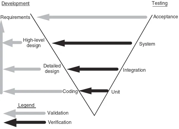
Testing plays an important role in achieving and assessing the quality of a software product [25]. On the one hand, we improve the quality of the products as we repeat atest–find defects–fixcycle during development. On the other hand, we assess how good our system is when we perform system-level tests before releasing a product. Thus, as Friedman and Voas [26] have succinctly described, software testing is a verification process for software quality assessment and improvement. Generally speaking, the activities for software quality assessment can be divided into two broad categories, namely,static analysis anddynamic analysis.
• Static Analysis: As the term “static” suggests, it is based on the examina-tion of a number of documents, namely requirements documents, software models, design documents, and source code. Traditional static analysis includes code review, inspection, walk-through, algorithm analysis, and proof of correctness. It does not involve actual execution of the code under development. Instead, it examines code and reasons over all possible behav-iors that might arise during run time. Compiler optimizations are standard static analysis.
• Dynamic Analysis: Dynamic analysis of a software system involves actual program execution in order to expose possible program failures. The behav-ioral and performance properties of the program are also observed. Pro-grams are executed with both typical and carefully chosen input values. Often, the input set of a program can be impractically large. However, for practical considerations, a finite subset of the input set can be selected. Therefore, in testing, we observe some representative program behaviors and reach a conclusion about the quality of the system. Careful selection of a finite test set is crucial to reaching a reliable conclusion.
By performing static and dynamic analyses, practitioners want to identify as many faults as possible so that those faults are fixed at an early stage of the software development. Static analysis and dynamic analysis are complementary in nature, and for better effectiveness, both must be performed repeatedly and alternated. Practitioners and researchers need to remove the boundaries between static and dynamic analysis and create a hybrid analysis that combines the strengths of both approaches [27].
1.4 VERIFICATION AND VALIDATION
Two similar concepts related to software testing frequently used by practitioners are
realized by a set of concrete, executable activities. The two concepts are explained as follows:
• Verification: This kind of activity helps us in evaluating a software system by determining whether the product of a given development phase satisfies the requirements established before the start of that phase. One may note that a product can be an intermediate product, such as requirement speci-fication, design specispeci-fication, code, user manual, or even the final product. Activities that check the correctness of a development phase are called
verification activities.
• Validation: Activities of this kind help us in confirming that a product meets its intendeduse. Validation activities aim at confirming that a product meets its customer’s expectations. In other words, validation activities focus on the final product, which is extensively tested from the customer point of view. Validation establishes whether the product meets overall expectations of the users.
Late execution of validation activities is often risky by leading to higher development cost. Validation activities may be executed at early stages of the software development cycle [28]. An example of early exe-cution of validation activities can be found in the eXtreme Programming (XP) software development methodology. In the XP methodology, the cus-tomer closely interacts with the software development group and conducts acceptance tests during each development iteration [29].
The verification process establishes the correspondence of an implementation phase of the software development process with its specification, whereas validation establishes the correspondence between a system and users’ expectations. One can compare verification and validation as follows:
• Verification activities aim at confirming that one isbuilding the product cor-rectly, whereas validation activities aim at confirming that one isbuilding the correct product [30].
• Verification activities review interim work products, such as requirements specification, design, code, and user manual, during a project life cycle to ensure their quality. The quality attributes sought by verification activities are consistency, completeness, and correctness at each major stage of sys-tem development. On the other hand, validation is performed toward the end of system development to determine if the entire system meets the customer’s needs and expectations.
1.5 FAILURE, ERROR, FAULT, AND DEFECT 9
1.5 FAILURE, ERROR, FAULT, AND DEFECT
In the literature on software testing, one can find references to the termsfailure,
error,fault, anddefect. Although their meanings are related, there are important distinctions between these four concepts. In the following, we present first three terms as they are understood in the fault-tolerant computing community:
• Failure: A failure is said to occur whenever the external behavior of a system does not conform to that prescribed in the system specification.
• Error: An error is astate of the system. In the absence of any corrective action by the system, an error state could lead to a failure which would not be attributed to any event subsequent to the error.
• Fault: A fault is the adjudged cause of an error.
A fault may remain undetected for a long time, until some event activates it. When an event activates a fault, it first brings the program into an intermediate error state. If computation is allowed to proceed from an error state without any corrective action, the program eventually causes a failure. As an aside, in fault-tolerant com-puting, corrective actions can be taken to take a program out of an error state into a desirable state such that subsequent computation does not eventually lead to a failure. The process of failure manifestation can therefore be succinctly represented as a behavior chain [31] as follows: fault→error→failure. The behavior chain can iterate for a while, that is, failure of one component can lead to a failure of another interacting component.
The above definition of failure assumes that the given specification is accept-able to the customer. However, if the specification does not meet the expectations of the customer, then, of course, even a fault-free implementation fails to satisfy the customer. It is a difficult task to give a precise definition of fault, error, or failure of software, because of the “human factor” involved in the overall acceptance of a system. In an article titled “What Is Software Failure” [32], Ram Chillarege com-mented that in modern software business software failure means “the customer’s expectation has not been met and/or the customer is unable to do useful work with product,” p. 354.
Roderick Rees [33] extended Chillarege’s comments of software failure by pointing out that “failure is a matter of function only [and is thus] related to purpose, not to whether an item is physically intact or not” (p. 163). To substantiate this, Behrooz Parhami [34] provided three interesting examples to show the relevance of such a view point in wider context. One of the examples is quoted here (p. 451):
Consider a small organization.Defectsin the organization’s staff promotion policies can cause improper promotions, viewed asfaults. The resulting ineptitudes & dissatisfac-tions areerrorsin the organization’s state. The organization’s personnel or departments probably begin tomalfunctionas result of the errors, in turn causing an overall degra-dation of performance. The end result can be the organization’s failure to achieve its goal.
context, a software system may be defective due to design issues; certain system states will expose a defect, resulting in the development of faults defined as incor-rect signal values or decisions within the system. In industry, the term defect is widely used, whereas among researchers the term fault is more prevalent. For all practical purpose, the two terms are synonymous. In this book, we use the two terms interchangeably as required.
1.6 NOTION OF SOFTWARE RELIABILITY
No matter how many times we run the test–find faults–fix cycle during software development, some faults are likely to escape our attention, and these will even-tually surface at the customer site. Therefore, a quantitative measure that is useful in assessing the quality of a software is itsreliability [35].Software reliability is defined as the probability of failure-free operation of a software system for a speci-fied time in a specispeci-fied environment. The level of reliability of a system depends on those inputs that cause failures to be observed by the end users. Software reliability can be estimated viarandom testing, as suggested by Hamlet [36]. Since the notion of reliability is specific to a “specified environment,” test data must be drawn from the input distribution to closely resemble the future usage of the system. Captur-ing the future usage pattern of a system in a general sense is described in a form called theoperational profile. The concept of operational profile of a system was pioneered by John D. Musa at AT&T Bell Laboratories between the 1970s and the 1990s [37, 38].
1.7 OBJECTIVES OF TESTING
The stakeholders in a test process are the programmers, the test engineers, the project managers, and the customers. A stakeholder is a person or an organization who influences a system’s behaviors or who is impacted by that system [39]. Different stakeholders view a test process from different perspectives as explained below:
• It does work: While implementing a program unit, the programmer may want to test whether or not the unit works in normal circumstances. The programmer gets much confidence if the unit works to his or her satisfac-tion. The same idea applies to an entire system as well—once a system has been integrated, the developers may want to test whether or not the system performs the basic functions. Here, for the psychological reason, the objective of testing is to show that the system works, rather than it does not work.
1.8 WHAT IS A TEST CASE? 11
• Reduce the risk of failure: Most of the complex software systems contain faults, which cause the system to fail from time to time. This concept of “failing from time to time” gives rise to the notion of failure rate. As faults are discovered and fixed while performing more and more tests, the failure rate of a system generally decreases. Thus, a higher level objective of performing tests is to bring down the risk of failing to an acceptable level.
• Reduce the cost of testing: The different kinds of costs associated with a test process include
the cost of designing, maintaining, and executing test cases, the cost of analyzing the result of executing each test case, the cost of documenting the test cases, and
the cost of actually executing the system and documenting it.
Therefore, the less the number of test cases designed, the less will be the associated cost of testing. However, producing a small number of arbitrary test cases is not a good way of saving cost. The highest level of objective of performing tests is to produce low-risk software with fewer number of test cases. This idea leads us to the concept of effectiveness of test cases. Test engineers must therefore judiciously select fewer, effective test cases.
1.8 WHAT IS A TEST CASE?
In its most basic form, atest case is a simple pair of<input, expected outcome>. If a program under test is expected to compute the square root of nonnegative numbers, then four examples of test cases are as shown in Figure 1.3.
In stateless systems, where the outcome depends solely on the current input, test cases are very simple in structure, as shown in Figure 1.3. A program to compute the square root of nonnegative numbers is an example of a stateless system. A compiler for the C programming language is another example of a stateless system. A compiler is a stateless system because to compile a program it does not need to know about the programs it compiled previously.
In state-oriented systems, where the program outcome depends both on the current state of the system and the current input, a test case may consist of a
TB1: <0, 0>,
TB2: <25, 5>,
TB3: <40, 6.3245553>,
TB4: <100.5, 10.024968>.
TS1: <check balance, $500.00>,<withdraw, ‘‘amount?’’>,
<$200.00, ‘‘$200.00’’>,<check balance, $300.00>.
Figure 1.4 Example of a test case with a sequence of<input, expected outcome>.
sequence of<input, expected outcome>pairs. A telephone switching system and an automated teller machine (ATM) are examples of state-oriented systems. For an ATM machine, a test case for testing thewithdraw function is shown in Figure 1.4. Here, we assume that the user has already entered validated inputs, such as the cash card and the personal identification number (PIN).
In the test case TS1, “check balance” and “withdraw” in the first, second, and fourth tuples represent the pressing of the appropriate keys on the ATM keypad. It is assumed that the user account has $500.00 on it, and the user wants to withdraw an amount of $200.00. The expected outcome “$200.00” in the third tuple represents the cash dispensed by the ATM. After the withdrawal operation, the user makes sure that the remaining balance is $300.00.
For state-oriented systems, most of the test cases include some form of deci-sion and timing in providing input to the system. A test case may include loops and timers, which we do not show at this moment.
1.9 EXPECTED OUTCOME
An outcome of program execution is a complex entity that may include the following:
• Values produced by the program:
Outputs for local observation (integer, text, audio, image)
Outputs (messages) for remote storage, manipulation, or observation
• State change:
State change of the program
State change of the database (due to add, delete, and update operations)
• A sequence or set of values