PREVENTION AND
DETECTION
FOR THE
TWENTY
-FIRST
CENTURY
The author and publisher have taken care in the preparation of this book, but make no expressed or implied warranty of any kind and assume no responsibility for errors or omissions. No liability is assumed for incidental or consequential damages in connection with or arising out of the use of the information or programs contained herein. The publisher offers excellent discounts on this book when ordered in quantity for bulk purchases or special sales, which may include electronic versions and/or custom covers and content particular to your business, training goals, marketing focus, and branding interests. For more information, please contact:
U.S. Corporate and Government Sales (800) 382-3419
corpsales@pearsontechgroup.com For sales outside the United States please contact:
International Sales international@pearson.com Visit us on the Web: informit.com/aw
Library of Congress Cataloging-in-Publication Data: Trost, Ryan.
Practical intrusion analysis : prevention and detection for the twenty-first century / Ryan Trost.
p. cm. Includes index.
ISBN-13: 978-0-321-59180-7 (pbk. : alk. paper) ISBN-10: 0-321-59180-1
1. Computer networks--Security measures. 2. Computer networks--Monitoring. 3. Computer security. 4. Computers--Access control. I. Title.
TK5105.59.T76 2009 005.8--dc22
2009019158 Copyright © 2010 Pearson Education, Inc.
All rights reserved. Printed in the United States of America. This publication is protected by copyright, and permission must be obtained from the publisher prior to any prohibited reproduction, storage in a retrieval system, or transmission in any form or by any means, electronic, mechanical, photocopying, recording, or likewise. For information regarding permissions, write to:
Pearson Education, Inc Rights and Contracts Department 501 Boylston Street, Suite 900 Boston, MA 02116 Fax (617) 671-3447 ISBN-13: 978-0-321-59180-7 ISBN-10: 0-321-59180-1
me and somehow sustained my endless IT ramblings. And to my wife’s family, the Arbacas clan, who have only had to endure my InfoSec rambling for a couple years and still invite me to dinner.
Preface xv
Chapter 1 Network Overview 1
Key Terms and Concepts 2
Brief History of the Internet 2
Layered Protocols 3
TCP/IP Protocol Suite 10
Internet Protocol 14
Addressing 21
IP Addresses 22
IPv6 27
Summary 29
Chapter 2 Infrastructure Monitoring 31
Network-Analysis Tools 32
Packet Sniffing 35
Accessing Packets on the Network 40
SPANs (Port Mirroring) 40
Network Taps 43
To Tap or to SPAN 48
Defense-in-Depth 50
Summary 51
viii
Chapter 3 Intrusion Detection Systems 53
IDS Groundwork 54
From the Wire Up 55
DoS Attacks 55
IP Fragmentation 57
TCP Stream Issues 58
Target-Based Reassembly 59
Two Detection Philosophies: Signature and Anomaly Based 60
Snort: Signature-Based IDS 61
Two Signature Writing Techniques 67
Bro: An Anomaly-Based IDS 74
Similarities Between the Systems 82
Summary 85
Chapter 4 Lifecycle of a Vulnerability 87
A Vulnerability Is Born 87
FlashGet Vulnerability 88
Collecting a Sample Packet Capture 90
Packet Analysis and Signature-Writing 95
Signature Tuning 100
Detection Tuning 100
Performance Tuning 101
Advanced Examples 104
CitectSCADA ODBC Server Buffer Overflow: Metasploit 104 FastStone Image Viewer Bitmap Parsing 109
Libspf2 DNS TXT Record Size Mismatch 114
Summary 117
Chapter 5 Proactive Intrusion Prevention and Response via Attack Graphs 119
Topological Vulnerability Analysis (TVA) 121
Overview of Approach 121
Illustrative Example 122
Limitations 125
Attack Modeling and Simulation 126
Network Attack Modeling 126
Attack Simulation 130
Optimal Network Protection 134
Vulnerability Mitigation 135
Attack Graph Visualization 137
Intrusion Detection and Response 141
Intrusion Detection Guidance 141
Attack Prediction and Response 144
Summary 147
Acknowledgments 147
Endnotes 148
Chapter 6 Network Flows and Anomaly Detection 151
IP Data Flows 152
NetFlow Operational Theory 153
A Matter of Duplex 155
Cisco IOS NetFlow and Flexible NetFlow 156
sFlow: More Data, But Less Frequency 159
Internet Protocol Flow Information Export (IPFIX) 161
It’s a Virtual World 162
Endless Streams of Data 164
Behavioral Analysis and Anomaly Detection 167
Compare and Contrast 172
IDS and NetFlow 172
Signature Updates 173
IDS System Resources 174
Syslog and NetFlow 178
Technology Matrix 180
Summary 182
Endnotes 183
Chapter 7 Web Application Firewalls 185
Web Threat Overview 186
Why a WAF? 189
WAF Protection Models 191
Positive Security Model 191
Negative Security Model 192
Virtual Patching Model 193
Output Detection Model/Content Scrubbing 194
WAF Policy Models 195
Learning 195
Vulnerability Assessment Feedback 195
ModSecurity 196
ModSecurity Rule Sets 196
VA+WAF 201
VA+WAF Example: WhiteHat Security and F5 Networks 201
WAFs and PCI Compliance 203
WAF Realities 203
IDS/IPS != WAF 204
False Positives 205
Misconfigured WAFs 205
WAFs Do Not Fix Bad Logic 205
WAFs != Bad Code Patch 206
Summary 206
References 207
Chapter 8 Wireless IDS/IPS 209
Why a Wireless IDS? 209
Wireless Intrusion Detection/Prevention Realities 212
Types of Wireless IDSs/IPSs 213
Overlay 213
Combined AP/WIDS 214
Combined AP/WIDS/Access Controller 215
Wireless IDS Events 215
Unauthorized Activity 216
Active Recon/Cracking 217
DoS Attacks 221
Intrusion Prevention Techniques 224
Limitations 224
Isolation 225
WEP Cloaking (WEP Chaffing) 228
Location Detection 229
Honeypot 231
Other Wireless Threats 233
Legacy Wireless Technology 233
Bluetooth 233
Sniffers 233
Summary 234
Endnote 234
Chapter 9 Physical Intrusion Detection for IT 235
Origins of Physical Security 236
Assumed, Yet Overlooked 236
A Parallel Universe to IT Security 239
Physical Security Background 241
Common Physical Access Control Components 243
This Is Not Your Father’s CCTV 255
Old Habits Die Hard 259
Convergence of Physical and Logical Security 260
How Convergence Works 261
HSPD-12: Convergence Trial by Fire 265
A Look at Some Vendor Offerings 266
Intrusion Detection Examples in a Converged Environment 270
Summary 274
Endnotes 274
Chapter 10 Geospatial Intrusion Detection 275
Current Uses of Geocoding 278
Introduction to Geographic Information Systems 279
GIS Basic Functions 282
Framework for Cooperation 282
Map Projection 283
Raster Versus Vector 285
Vector Data Model 287
Spatial Point Pattern Analysis 288
Classes of Spatial Analysis 289
Point Intensity 290
Point Process Statistics 290
Dynamics of a Professional Attack 293
Cornerstone Theory 295
Example of Attack Steps and Methods 296
Geocoding Techniques 299
Geocoding Limitations 315
Accuracy 316
Case Study of Geographic Intrusion Detection 320
Case Outline 322
Breakdown of the Steps 322
Summary 344
Endnotes 345
References 346
Chapter 11 Visual Data Communications 347
Introduction to Visualization 348
Developing a Visualization Strategy 355
User Audiences 356
Statistical Graphing Techniques 361
Technological Considerations 365
Scalability 365
Installation and Support 366
Data Management 368
Security Event Visualization 370
Example Graphs 371
Starlight Visual Information System 378
ETRI: VisNet and VisMon 381
Use-Case: Security Audit 385
Summary 387
Terminology 388
Endnotes 390
Reference 390
Chapter 12 Return on Investment: Business Justification 391
Not If, But When 393
Compliance Plays a Role 394
CoBIT Framework 394
ISO 27001/27002 Frameworks 395
ITIL Framework 396
Health Insurance Portability and Accountability Act of 1996 (HIPAA) 397 Payment Card Industry Data Security Standard (PCI-DSS) 398 Federal Information Security Management Act of 2002 (FISMA)/National
Institute of Standards and Technology 399
Security Breaches 400
Breach Costs 401
Security Investment Within the Organization 402
Data Breaches and the Law 402
ROI as a Unifying Benchmark 404
Cost Breakdown 405
Cost-Benefit Analysis: Building an Economic Model 408
Gain from Investment 409
Cost of Investment 413
Return on Investment 414
Net Present Value 414
Internal Rate of Return 416
ROI Versus NPV Versus IRR 417
Security Investment: Should Security Operations Be Outsourced? 418
Benefits of MSSPs 418
Downfalls of MSSPs 419
The Financial Aspect of an MSSP 422
Cyber Liability Insurance (CLI) 426
CLI Coverage Types 428
Privacy Liability Insurance 429
Network Security Liability Insurance 429
Property Loss Insurance 429
Loss of Revenue Insurance 429
Cyber Extortion Insurance 430
Notification Costs Insurance 430
Regulatory Defense Insurance 430
Media Liability Insurance 430
CLI Underwriting Process 431
Summary 432
Endnotes 434
Appendix Bro Installation Guide 435
Compiling and Building Options 437
Operations Use 438
References 440
Preface
This book was developed to help fill multiple gaps in practical intrusion detection within a single cover-to-cover publication. Traditionally, intrusion detection books concentrate on narrow subject matter that focuses on vendor-specific information, like Snort or Cisco MARS, Intrusion Detection System (IDS) installation, and sensor placement or signature writing. This book incorporates the essential core knowledge to understand the IDS, but it also expands the subject matter to other relevant areas of intrusion inter-est, such as NetFlow, wireless IDS/Intrusion Prevention System (IPS), physical security, and geospatial intrusion detection. Don’t get me wrong…the previously mentioned books are the foundation of my security knowledge, but as the industry matures to include various facets of incursion, its books should incorporate those facets into a single publication so security aficionados don’t have to fracture their attention across so many titles.
W
HOS
HOULDR
EADT
HISB
OOKThis book’s audience is any and all security practitioners; whether you’re an entry-level security analyst, a chief security officer, or even a prospective college student researching a career in network security. Every chapter might not provide a silver-bullet solution that protects your company from every well-versed attacker. But, as you peel back the onion layers, you will find a combination of included security defenses that help ensure your company’s security posture and out-endure even the most motivated attacker(s).
H
OW TOR
EADT
HISB
OOKphysical and logical security, and geospatial intrusion detection. Several traditional chap-ters explore new approaches, including ones that cover IDSs, vulnerability signature dis-section, and Web Application Firewalls (WAF).
I was lucky enough to have several knowledgeable friends that, with some begging and pleading, agreed to include their extensive security insight, experience, and opinions. I avoid duplicating materials presented in other books because I want to fill the gaps of current security initiatives and/or explore the arena of new concepts and strategies.
H
OWT
HISB
OOKI
SO
RGANIZEDThis book follows a compartmentalized organization because each chapter focuses on specific intrusion techniques. The beginning of this book introduces basic networking terminology, and it transitions into providing an overview of intrusion detection, which caters to the InfoSec newbies and finally dives into more sophisticated and advanced intrusion defenses. Here is a brief description of each chapter:
• Chapter 1, “Network Overview,” focuses on basic network structure and briefly explains the anatomy of TCP/IP and OSI. Most IT-related books must include some introduc-tory chapter to either define the foundation of the technology or refresh readers that might not deal with it in their daily lives; this book is no different. It is not meant to be an in-depth analysis, but it eases you into the more sophisticated work to come. • Chapter 2, “Infrastructure Monitoring,” explores some common network security
practices, including vulnerability assessments, packet sniffing, IDS, file integrity checking, password auditing, wireless toolkits, exploitation toolkits, and network reconnaissance tools. Network security heavily relies on the tools used to “see” the traffic. However, as the chapter title indicates, a majority of this chapter concentrates on mainstream monitoring capabilities and the never-ending battle between using a tap or SPAN for monitoring purposes.
• Chapter 3, “Intrusion Detection Systems,” provides you with insight into the IDS industry by introducing fundamental concepts and then progressively jumping into more complex topics, including evasion techniques, signature dissection, and a look into the Snort and BRO IDSs, while simultaneously providing as little duplication of previous material as possible. Most IDS books written in the past focus solely on Snort, snort.conf (Snort’s configuration file), and the signature syntax. However, few publications truly clarify the distinction between writing a signature looking for an exploit versus writing a signature identifying a system’s vulnerability. Finally, the chapter ends with an assessment of two open source systems, Snort and Bro, which take different approaches to intrusion detection.
• Chapter 4, “Lifecycle of a Vulnerability,” steps you through the natural evolution of a vulnerability, from discovering the vulnerability, to capturing the packet stream, to analyzing the malicious content within the packet, and writing an efficient Snort sig-nature to alert on it. It does all this, while simultaneously exposing you to a small sub-set of necessary tools to help you in your quest. The examples escalate in complexity and are specifically chosen to reflect relatively recent events, because they were all released within the past few months. For newcomers, the analysis of a packet might appear overwhelming and tedious, but if you segment it and step through the packet capture packet-by-packet, the process starts to fall into place. For the already skilled signature writers, the advanced examples, which use flowbits, PCRE, and newly shared object rules, shed some light on the thought process and technique that the Sourcefire VRT team uses.
• Chapter 5, “Proactive Intrusion Prevention and Response via Attack Graphs,” exam-ines proactive methods of attack risk reduction and response through attack graphs. Administrators and security analysts are overwhelmed by constant outside threats, complexity of security measures, and network growth. Today’s status quo for network defense is often reduced to mere triage and post-mortem remediation. The attack graphs map potential paths of vulnerability through a network, showing exactly how attackers might penetrate a network. Attack graph analysis identifies critical vulnera-bilities and provides strategies for protecting critical network assets. But, because of operational realities, vulnerability paths often remain visible. In such cases, attack graphs provide an ideal methodology for planning appropriate attack responses. This includes optimal placement of intrusion detection sensors, correlating intrusion alarms, accounting for missed detections, prioritizing alarms, and predicting the next possible attack steps.
• Chapter 6, “Network Flows and Anomaly Detection,” explores the topic of network flow data: its collection for network security analysis and, specifically, an emerging field called Network Behavior Analysis (NBA). First, this chapter explores flow tech-nology and analyzes the different flow formats: their characteristics, respective datasets, and key fields. It discusses how network flow deployments affect device per-formance and statistical sampling and then introduces possible data flow collection strategies. IDS and packet sniffing software are microanalytical tools that examine packet contents, data flow is a macroanalytical mechanism that characterizes large volumes of traffic in real time. Although traditional IDS/IPS technologies are still an environment staple, they are blind to specific attacks, whereas NBA fills those gaps and perfectly complements them because it excels at immediately detecting polymor-phic worms, zero-day exploits, and botnet denial of service (DoS) attacks.
becoming a solution of choice for companies who operate mission-critical Web sites. With the explosion of the Internet, an entire new family of attack vectors has been created that redefine the traditional concept of a threat. Whether it is the database server, Web server or even the visitors of the targeted site, these threats are often embedded in seemingly innocent traffic that many IDSs do not have the power or capability to detect.
• Chapter 8, “Wireless IDS/IPS,” details how wireless deployments have a whole new set of problems than traditional IDSs address. For the most part, intrusion detection focuses on the data passing from point A to point B. However, this is a limited view of data transmission, because it fails to consider the physical properties of the transmis-sion process. Thanks to wireless networking, data no longer has to exist as electronic pulses on a wire, but can now live as radio waves in the air. Unfortunately, this means traditional IDS solutions are no longer qualified to fully protect this information, if only because they cannot interpret RF energy. In this chapter, you gain an under-standing of the issues related to wireless security, the shortcomings of the network-based IDS, and the options available to those who want to keep a close eye on their wireless traffic.
• Chapter 9, “Physical Intrusion Detection for IT,” gets IT security staffs thinking about how intrusion detection efforts can be bolstered by converging with the physical secu-rity team. This chapter includes an overview of physical secusecu-rity technologies to help IT security personnel understand the perspective of the physical security team and familiarize themselves with the physical security technology terrain. A few example scenarios illustrate the possibilities of what converged detection can offer.
• Chapter 10, “Geospatial Intrusion Detection,” proves how the source IP address is one of the most overlooked and powerful components of an intrusion detection log. IDSs/IPSs are becoming more advanced, and geocoding source IP addresses is adding another layer of defensive intelligence. The ultimate goal of geospatial intrusion detection is to maximize situational awareness and threat visualization techniques among security analysts. Most attackers use multiple zombie machines to launch pro-fessional attacks, but even a zombie’s network reconnaissance leaves geographic fin-gerprints that are easily picked up by pattern recognition algorithms from the Geographic Information Systems (GIS) industry.
• Chapter 11, “Visual Data Communications”: Visualization of security data has become an increasingly discussed topic. As data retention policies increasingly capture the compliance spotlight, it is forcing companies to retain audit logs for extended time periods and, in some cases indefinitely. NetFlow is a perfect example of how beneficial visualizing data can be. As it samples the network traffic, an analyst can immediately
identify suspicious patterns. Countless possible datapoints can be tracked and visual-ized within a company’s network. The driving focus is to put into words that visualiz-ing security alerts are left to interpretation because what helps me defend my network might not help you preserve yours. This chapter provides a broad view of the different visualization possibilities.
• Chapter 12, “Return on Investment: Business Justification,” involves the nontechnical anomaly as it focuses on management decisions regarding intrusion detection secu-rity. This chapter conveys valuable insight on the compliance landscape, a breakdown on ROI strategies, and introduces cyber liability insurance. This chapter conveys valu-able insight for both today’s, and tomorrow’s, security directors. Regardless of what your security tier, you’re always training for the next escalation of privileges.
Acknowledgments
I attribute my security success and drive to family, colleagues, and hard work. My fasci-nation with network security all started with conversations with my little brother, Adam, who at the time was pursuing his computer science degree at the University of Virginia, all while I was finishing up my business management degree at York College of
Pennsylvania. As I spoke of economics and statistics, he introduced me to programming, networking, and cryptography, and he awakened my calling with IT and network secu-rity. Immediately after completing my undergrad, the thirst for a more in-depth techni-cal education level quickly became reality as I completed my master’s degree in computer science from George Washington University. In addition to my brother, I want to thank my parents and sister for their support and always motivating me. Who said a little bit of sibling rivalry isn’t healthy? Publications = Ryan +1.
Throughout my career, I have been privileged to work with some of the most intelli-gent and driven security professionals in the industry. I have been fortunate to work in atmospheres where managers welcome new ideas and coworkers share knowledge. I thank everyone at DeYoung & Associates for taking me under their wing (especially Marilyn) and introducing me to spaghetti code and computers. My next career move found me in the middle of a federal government project surrounded by an engineering and operations team, and the rules and regulations that all government-funded projects must comply with. I want to thank Margaret, Maryanne, Deb, Malek, Trung, Morales, Mohler, Farred, Dunia, Harwell, Assad, Roesch, Karabelas, Roney, Tom, Salim, Christina, Lisa, Mike, Dave, Dae, Jim, Stephanie, Quyen, Josh, and Tim.
My current residence at Comprehensive Health Services has been the most enriching, because it has the level of dedication and teamwork among the staff for which every CEO hopes. The company’s highly dynamic environment proves challenging, motivating work, and truth be told, even my worst day is better than most people’s best day. I thank the senior executives for the opportunity and I especially thank the IT team, including Chris, Todd, Dave, Peter, Foote, Wesam, Brian, Kasia®, Melissa, Christy, Ben, Chet, Jerry, PJ, Dan, Trish, Nadim, Mark, Christina, Bill, and the rest of the gang. I will continue to try and keep up if you continue to motivate and amaze me.
All security experts have an “inner circle” of security friends to whom they turn when they just are not 100 percent sure of a technology, a configuration setting, or even a sus-picious event log. To Rob Kerns, Luis Sepulveda, Orlando Ferreiras, Nate Miller, and
Trevor Hawthorn at Stratum Security, Richard Bejtlich, and of course, the technical contributors: Thanks for all the great advice and guidance.
I am especially grateful to several industry professionals that expanded my vision and brought their subject matter expertise to several chapters—I cannot express how grateful I am. Andy Wilson, a senior systems engineer at Lancope, for all his help and insight on the NBA chapter. Jake Babbins, who on short notice, helped me refine the intrusion detection chapter, specifically Bro. Barbara Bennett and Marcy Wilder from Hogan & Hartson took time from their hectic schedule to educate me on HIPAA and the new presidential stimulus package. Stephanie Shelton ensured that my GIS interpretations weren’t too far off the mark. Gary Connor at Quova opened his door and gave me a first-hand look at Quova’s strategies and methodology for translating IP addresses to geo-graphic coordinates…absolutely amazing! John McLaughlin helped me navigate through the cyber liability insurance obstacle course. I also want to express an ENORMOUS amount of gratitude to Ron O’Meara for assisting me with the organization and struc-ture of several chapters, but specifically the Visualization chapter. To all: Your dedication, experience, and suggestions were intuitive and a saving grace.
I also greatly appreciate the invaluable feedback from the technical review committee for their expertise, time and effort, Jan Monsch, Raffael Marty, and Tom Jacobs, whose insight absolutely strengthened this book. I also thank the Pearson folks, who have been integral in the publication of this book: Jessica Goldstein and Romny French guided me through the publication process, and Chris Zahn provided integral writing feedback and somehow saw through my infamous sentence structure! And last but not least, Jovana San Nicolas-Shirley, Sheri Cain, and the rest of the Indianapolis crew for their final review and layout assistance. THANKS!
About the Author
Ryan Trostis the Director of Security and Data Privacy Officer at Comprehensive Health Services where he oversees all the organization’s security and privacy decisions. He teaches several Information Technology courses, including Ethical Hacking, Intrusion Detection, and Data Visualization at Northern Virginia Community College. This enables him to continue exploring his technical interests among the endless managerial meetings. In his spare time, Ryan works to cross-pollinate network security, GIS, and data visualization. He is considered a leading expert in geospatial intrusion detection techniques and has spoken at several conferences on the topic, most notably DEFCON 16. Ryan participated as a RedTeamer in the first annual Collegiate Cyber Defense Competition (CCDC) and now fields a team of students in the annual event. Ryan has been a senior security consultant for several government agencies before transitioning over to the private sector. In 2005, Ryan received his masters of science degree in com-puter science from George Washington University where he developed his first geospatial intrusion detection tool.
About the
Contributing Authors
Seth Fogieis the CEO of Airscanner USA, where he oversees the research and develop-ment of security products for mobile platforms. Seth has coauthored several books, such asXSS Attacks,Aggressive Network Self Defense,Security Warrior, and even contributed to
PSP Hacks. Seth also writes articles for various online resources, including Pearson Education’s InformIT.com, where he is acting cohost for its security section. In addition, and as time permits, Seth provides training on wireless, Web application security, and mobile device security. He speaks at IT and security-related conferences and seminars, such as BlackHat, Defcon, and RSA.
Jeff Forristal, a.k.a. Rain Forest Puppy and creator of libwhisker, is a senior security pro-fessional with more than a decade of security-specific experience. He currently works for Zscaler, and he previously worked at HP, SPI Dynamics, and Neohapsis in senior posi-tions related to security consulting and security research. Jeff has written multiple arti-cles and cover stories for Network ComputingandSecure Enterprisemagazines on various topics, such as physical security, source code static analysis products, and network vul-nerability scanners.
Dr. Sushil Jajodiais a university professor, BDM International Professor of Information Technology, and the director of the Center for Secure Information Systems at the George Mason University, Fairfax, Virginia. He joined GMU after serving as the director of the Database and Expert Systems Program at the National Science Foundation. Before that, he was the head of the Database and Distributed Systems Section at the Naval Research Laboratory, Washington. He received the 1996 Kristian Beckman award from IFIP TC 11 for his contributions to the discipline of information security, the 2000 Outstanding Research Faculty Award from George Mason’s Volgenau School of Information Technology and Engineering, and the 2008 ACM SIGSAC Outstanding Contributions Award for his research and teaching contributions to the information security field and his service to the ACM SIGSAC and the computing community. Dr. Jajodia is the found-ing editor-in-chief ofJournal of Computer Securityand on the editorial boards ofIET Information Security,International Journal of Cooperative Information Systems,
International Journal of Information and Computer Security, and International Journal of Information Security and Privacy.
Alex Kirk’s earliest memories revolve around computers, including learning to type on his parents’ TRS-80 Model III at the age of 4. Following a high school journalism career that included a stint as editor-in-chief of a paper ranked ninth in the country by the National Scholastic Press Association, Alex worked briefly as a freelancer for The Sacramento Beebefore attending George Washington University as a journalism major. The fiscal lure of the dot-com boom led him to switch his career focus in 2000, when he took a job as a Web master contracting to the U.S. Department of Agriculture. After completing a degree in computer information systems at Strayer University and surviv-ing a pair of post-bubble layoffs, Alex joined the Sourcefire Vulnerability Research Team in early 2004, and has since become an expert in all things Snort. Alex continues to write in his spare time, including an article published in the August 2001 issue ofSysAdmin
magazine on CheckPoint firewalls and work as a public relations officer for The Mars Society, a nonprofit space advocacy group. Since joining the Sourcefire team, Alex has become one of the world’s leading experts on intrusion detection using Snort.
Knowledge of the structure of Internet Protocol (IP) packets is a fundamental part of understanding the Internet and how information moves from one point to another. The benefits of such knowledge extend to virtually all networking disciplines, not the least of which is intrusion detection. Rules-based intrusion-detection mechanisms, for example, can flag packets as suspicious if their structure mimics that of a known malicious string. While this is happening, another rule might cause an action in response to a packet that has no conceivable reason to exist, as when both the SYN and RST flags are set. There are many ways to probe and attack from within a packet, and the problem only gets worse as a network gets larger. The shotgun approach of enabling all possible Intrusion Detection Systems (IDS) rules is sure to fail in most environments, particularly when busy, high-speed circuits threaten to overtax IDS deployments that must decode every packet on the wire. In IP networks, bit-level expertise cannot be overvalued when you are designing solutions or choosing the most appropriate defense technologies.
The topic of this chapter—the structure and functions of TCP/IP—is uniquely appro-priate in any discussion of intrusion-detection techniques. This chapter begins with a clarification of key terms and concepts, and then it discusses the genesis of current refer-ence models that were introduced in the early 1980s. Following that is a detailed exami-nation of TCP/IP, and the final section describes modern networking.
1
2
K
EYT
ERMS ANDC
ONCEPTSIt is important to clarify certain key terms that this chapter uses. Readers who know the standards that are under review by more than one name will see them here as TCP/IP and the OSI Model, which represent Transmission Control Protocol over Internet Protocol
andOpen Systems Interconnection, respectively. Because all the popular terms are essen-tially correct, it is best to declare this common ground before the details are discussed.
When reading technical information or preparing for a network-analysis effort, it helps to have certain issues and concepts in mind. These items serve that purpose regarding TCP/IP and the OSI Model:
•
All implementations are not created equal. Conforming to standards made by devel-opers and manufacturers is practically voluntary.•
In nearly all real-world cases, the OSI Model nomenclature is used in documents and discussions, regardless of the technology.•
Although it can be made to work, communication between TCP/IP and the OSI Model systems can have undesirable effects, at least in the form of more difficult implementation.B
RIEFH
ISTORY OF THEI
NTERNETThe goal that was realized by the creation of this protocol mix, which is often called a “protocol stack,” is a means for open communication between disparate computers. The driving forces behind the Internet was the United States Department of Defense (DoD), specifically the Defense Advanced Research Projects Agency (DARPA), and two interna-tional organizations: the Internainterna-tional Organization for Standardization (ISO) and the International Telecommunications Union (ITU).
DARPA began work on its network, ARPANET, in 1968, which went into full produc-tion in 1970. At the time, the protocol in use was the ARPANET Network Control Program (NCP) host-to-host protocol, and the first five nodes added belonged to Bolt, Beranek, and Newman (BBN); Stanford University; UCLA; UC Santa Barbara; and the University of Utah.
•
RFC 791, Internet Protocol•
RFC 793, Transmission Control ProtocolThese are the most current RFC numbers and descriptions; the authoritative organi-zation of the day was the Internet Configuration Control Board (ICCB), who designated the original releases as RFC 760, DoD Standard Internet Protocol and RFC 761, DoD Standard Transmission Control Protocol.
In the mid to late 1970s, the ITU and ISO were working independently to develop an open set of standards for network architectures. This presented significant challenges that DARPA did not encounter, which, by comparison, operated in a controlled environ-ment. The ISO and ITU architects faced the daunting task of convincing equipment manufacturers to agree with each and every standard.
ISO and ITU established a positive vendor relationship with Honeywell Information Systems, which worked with the international teams. In 1984, the ITU and ISO teams merged their respective standards work into a single document, and much of the final product came from Honeywell engineers. The standards document was released under the umbrella name Open Systems Interconnection, which is now referred to as the OSI Reference Model (or simply the OSI Model). The cooperating international organiza-tions designate the specification as follows:
•
ITU-T, X-Series Recommendation X.200•
ISO 7498, Open Systems Interconnection, Basic Reference ModelThe ARPANET transition to TCP/IP happened between October 1981 and October 1983. During this time, the protocols were intensely researched and scrutinized by their developers. The official release came on January 1, 1983, and the Internet was born. The headstart that was gained by the development period and 1983 release date is said to be the reason that TCP/IP is now the global standard for Internet communications. Now that you have an abridged knowledge of the history of the Internet it’s time to explore the OSI Model and TCP/IP.
L
AYEREDP
ROTOCOLSInternet hosts communicate by using a special software mechanism called layers(or
4
NOTE
The depiction of layers might depend on which reference document is chosen as the authoritative model. Although most Internet Engineering Task Force (IETF) documents reference TCP/IP as having the four layers shown in Figure 1-1, RFC 1983, “Internet User’s Glossary,” lists the number of layers at five. Commercial doc-uments also reflect this difference, but Cisco Systems, the current and long-standing leader in network technologies, teaches in CCENT/CCNA ICND1 Official Exam Certification Guide(Odom 2007) that TCP/IP has four layers.
Figure 1-1 makes it easy to understand why the world is comfortable with TCP/IP as the Internet standard protocol suite, but it still uses the OSI Model terms in documents and discussions. The end result is the same with both versions, but TCP/IP has an edge over the OSI Model in terms of simplicity. The Internet Society can divide TCP/IP into two areas of responsibility in support of developers and users: The lower three layers (link, Internet, and transport) are the communication layers, which focus on networking requirements, and the application layer covers host software. On the other hand, the OSI Model gives the technical community a clear set of terms for communication between humans. A minor point is the fact that many readers interpret Figure 1-1 to be based on “incorrect” names. For example, the link layer is also known as the access layer and media access layer.
As previously mentioned, OSI Model nomenclature is used in nearly all discussions and documents, even though TCP/IP is the Internet standard. Figure 1-1 shows that TCP/IP is at Layer 2 if the counting starts at the bottom and moves up; however, because it is functionally the same as the OSI Model network layer, referring to it as a Layer 3 protocol causes no problems.
TCP/IP OSI Model Application Presentation
Session Transport
Network Data Link Physical Application
Transport Internet
Link
Figure 1-1 TCP/IP and OSI Model comparison
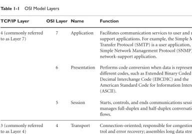
Table 1-1 OSI Model Layers
TCP/IP Layer OSI Layer Name Function
4 (commonly referred to as Layer 7)
7 Application Facilitates communication services to user and network support applications. For example, the Simple Mail Transfer Protocol (SMTP) is a user application, and the Simple Network Management Protocol (SNMP) is a network-support application.
6 Presentation Performs code conversion when data is represented by different codes, such as Extended Binary Coded Decimal Interchange Code (EBCDIC) and the American Standard Code for Information Interchange (ASCII).
5 Session Starts, controls, and ends communications sessions; manages full-duplex and half-duplex conversation flows.
3 (commonly referred to as Layer 4)
6
Table 1-1 OSI Model Layers
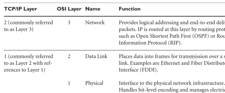
TCP/IP Layer OSI Layer Name Function
2 (commonly referred to as Layer 3)
3 Network Provides logical addressing and end-to-end delivery of packets. IP is routed at this layer by routing protocols, such as Open Shortest Path First (OSPF) or Routing Information Protocol (RIP).
1 (commonly referred to as Layer 2 with ref-erences to Layer 1)
2 Data Link Places data into frames for transmission over a single link. Examples are Ethernet and Fiber Distributed Data Interface (FDDI).
1 Physical Interface to the physical network infrastructure. Handles bit-level encoding and manages electrical characteristics of the circuit.
Consider an analogy of what is required for a personal computer in Redmond, Washington, to converse with a mainframe computer in Armonk, New York:
1.The first, and most obvious, requirement is that both computers must be physically connected to a network that, in turn, has physical connectivity between the locations. 2.The computers need to be told that they can talk and decipher the communication
that comes their way as being real or garbage (errors).
3.At least one of the computers in the conversation must know the address of the other computer and the wherewithal to initiate the data communication.
4.The data traffic might be heavy, so both computers need to know how to go with the flow and have their data arrive in one piece at the other end.
5.The participants must have the sense not to talk at the same time. They must know when to shut up!
6.Knowing that they are foreign to each other, an interpreter must be available. 7.The personal computer and mainframe can exchange information.
Disregarding that this analogy is fiction, the conversation became easier because traf-fic cops along the route did not spend time meeting all the same requirements. All they needed was physical connectivity, a common language for communication, and a list of recipient addresses that they could share.
•
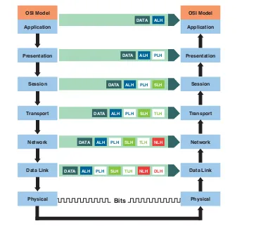
Same-layer interaction. The layered networking model has a peer-to-peer interac-tion between equal layers on different computers.•
Adjacent-layer interaction. Layered networking involves an interaction between adjacent layers on the same computer.The same-layer interaction is how each layer communicates its intended action to its peer on the receiving end of a connection. Adjacent-layer interaction involves attaching a PDU to a protocol header as it moves through the layers, which is a process called
encapsulation. As its name implies, a header is at the front of the transmitted data and is the first thing that the receiving host interprets. It contains source and destination addresses, and it can include error checking or other fields. Figure 1-2 and Figure 1-3 show same-layerandadjacent-layercommunications.
OSI Model
Application
Presentation
DATA ALH
DATA ALH PLH
DATA ALH PLH SLH
DATA ALH PLH SLH TLH
DATA ALH PLH SLH TLH NLH
DATA ALH PLH SLH TLH NLH DLH
Session
Transport
Network
Data Link
Physical Bits
OSI Model
Application
Presentation
Session
Transport
Network
Data Link
Physical
8
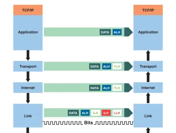
An example using TCP/IP hosts shows how layered protocols enable communication. Assume that a host application program needs to send data to another host that is sev-eral hops away. Figure 1-4 illustrates the following steps:
1.The application program at the originating host passes its data, the destination address, and other parameters required to the transport layer as arguments in a sys-tem call.
TCP/IP
Application
Transport
DATA ALH
DATA ALH TLH
DATA ALH TLH
DATA ALH ILH ILH LLH
Internet
Link
Bits
TCP/IP
Application
Transport
Internet
Link
Figure 1-3 TCP/IP same-layer and adjacent-layer interactions
Gateway Gateway
Ethernet
HDLC HDLC
Ethernet
2.The transport layer encapsulates the data by attaching it to a header that it has cre-ated and then passes it to the Internet layer.
3.The Internet layer encapsulates the data inside an IP header and passes it to the link layer.
4.The link layer (in this example, Ethernet) encapsulates the data as a frame inside an Ethernet header and trailer for transmission by the physical media.
5.Data is encoded as bits on the physical medium. This is called electrical encoding. 6.The Ethernet frame arrives at the interface of a router that is on the same segment.
The router also has a connection to the wide area network (WAN). This router func-tions as a gateway.1
7.The IP packet is extracted and routed to the next hop in the path. At this point, the entire operation is internal to the router, which effectively switches the packet from its Ethernet interface to a WAN interface; in this example, it is a serial interface. This is path switching, not switched Ethernet.
8.The serial interface is configured to use high-level data link control (HDLC) as the WAN protocol, so the packet is encapsulated inside an HDLC frame, and then for-warded over the WAN to the next hop in the path. HDLC is a Layer 2 protocol in OSI terminology.
9.At each hop, the IP packet is extracted, switched to an outbound interface, and encapsulated as required for transmission to the next hop.
10.Routing along the way to the final destination is facilitated by routing protocol oper-ations in each hop. Path selection is based on IP address tables (routing tables) and routing algorithms, such as Open Shortest Path First (OSPF) and Interior Gateway Routing Protocol (IGRP). Large networks that are logically divided into “domains” also use special routing protocols for interdomain path selection, such as Border Gateway Protocol (BGP).
11.At the destination router, the IP packet is extracted and switched to an outbound Ethernet interface; the destination host is on this segment.
12.The packet is encapsulated inside an Ethernet header and trailer.
13.The Ethernet frame is encoded in electrical bits, transmitted over the physical medium, and delivered to the interface of the destination host.
1The word gateway references functionality, not a special type of device. In TCP/IP terms, gateway and router
10
14.The Internet layer extracts the IP packet from the Ethernet frame and passes it to the transport layer.
15.The transport layer ensures that all segments are in order and delivers the data to the host application program.
TCP/IP P
ROTOCOLS
UITESpecifications in RFC 1122,“Requirements for Internet Hosts—Communication Layers,” state that Internet hosts must implement at least one protocol from each layer of the TCP/IP protocol suite. In light of the fact that the link, Internet, and transport layer protocols must be operational for an implementation to work, it might appear as though the IETF is “requiring the obvious.” Additional details clarify the requirement by distin-guishing two categories of application layer protocols:user protocolsthat provide services to users, and support protocolsthat enable common system functions. RFC authors explain that the most common examples of each are as follows:
•
Application layer user protocols. Telnet, File Transfer Protocol (FTP), and Simple Mail Transfer Protocol (SMTP).•
Application layer support protocols. Simple Network Management Protocol (SNMP), BOOTP, Reverse Address Resolution Protocol (RARP), and Domain Name System (DNS).Tables 1-2 through 1-5 offer brief definitions of these protocols and others that are widely used today. To be consistent with typical industry language, OSI Model terms describe the layers at which each protocol operates.
Although developers have latitude for implementing the TCP/IP protocol suite, there are some stringent requirements to consider. A good example is the robustness principle, which stresses that software is written in such a way that it deals with every conceivable error condition. The principle also involves performance in a network-friendly manner and drives the point home with specific verbiage, such as “be liberal in what you accept and conservative in what you send.”
To clarify, for applications that do not require reliable transport services, UDP is avail-able. This is called a UDP/IP application, and it is distinct from TCP/IP.
Table 1-2 Application Layer Protocols
Application Layer Protocol Description
Domain Name System (DNS) A data query service that is used primarily to translate human-readable system names into IP addresses. The query parameter is an Internet host name that is associated with the address. It is called the Domain Name System instead of Host Name System because its services are of a global nature. For example, a Web site’s host name can be as simple as ABCD; the fully qualified domain name (FQDN) would be ABCD.com, assum-ing that it is operated by a commercial entity. Country domain names, such as .us or .uk, are based on ISO specification 3166.
File Transfer Protocol (FTP) Enables users to transfer files to and from other hosts. Typically, FTP is used to transfer large files that are not e-mail friendly, such as images, hefty database files, or in my case, wedding photos from the wedding photographer.
Hyper Text Transfer Protocol (HTTP)
Used on the Internet to transfer hypertext markup language (HTML) files. Since its creation, an increasing number of applications have been built for transferring information in Web pages with HTTP as the foun-dation.
Simple Mail Transfer Protocol (SMTP)
Transfers electronic mail. SMTP is completely transparent to users. Behind the scenes, SMTP connects to remote machines and transfers mail messages much like FTP transfers files.
Simple Network Management Protocol (SNMP)
The Internet standard protocol for device management. It reads data from device Management Information Base (MIB) tables, which can create performance and health reports. SNMP also sets parameters in remote devices, and it supports real-time event and alert generation. Software in the managed device is called an SNMP agent, while software at the operator’s end of the network is called a network management system.
12
Table 1-3 Session Layer Protocols
Session Layer Protocol Description
Remote Procedure Call (RPC) Session layer
Implements the client-server model of distributed computing. Its main function is to remotely request the execution of a particular process.
Table 1-2 Application Layer Protocols
Application Layer Protocol Description
Kerberos A widely supported security protocol for centralized authentication management. Kerberos uses a special application, called an authentica-tion server, to validate passwords and encrypauthentica-tion schemes.
Network File System (NFS) A network file-sharing protocol developed by Sun Microsystems. It allows computers to access and use files on other systems over the net-work as if they were on a local disk. This is accomplished by a distrib-uted file system scheme. It is the de facto Internet standard for remote file management.
Telnet The Internet standard protocol for remote terminal connection services. Although it is intended for a hands-on user, many shops employ automation scripts that periodically open Telnet sessions to perform a particular function. This is negative from both security and perform-ance perspectives because it transfers results over the network in unen-crypted packets and generates much overhead traffic. Telnet is being replaced by Secure Shell (SSH), which provides encrypted and secure remote terminal access.
Server Message Block (SMB) A network file-sharing protocol developed by Microsoft. It allows com-puters to access and use files on other systems over the network as if they were on a local disk.
Trivial File Transfer Protocol (TFTP)
Table 1-5 Internet Layer Protocols
Internet Layer Protocol Description
Internet Control Message Protocol (ICMP)
An extension to IP that facilitates the generation of error messages and test packets, and it manages informational messages. It has been a part of the TCP/IP protocol suite from the beginning, and it is an important part of making IP work. It is so important, in fact, that RFC 1122, “Requirements for Internet Hosts—Communication Layers,” states a requirement that “the Internet layer of host software MUST implement both IP and ICMP.”
Internet Protocol (IP) The packet-switching protocol for TCP/IP; it uses logical addressing.
Table 1-4 Transport Layer Protocols
Transport Layer Protocol Description
Secure Shell (SSH) Used for secure remote login capabilities over an otherwise unsecured network. It is slowly replacing Telnet as the preferred method of remotely accessing devices. SSH has three compo-nents: Secure Shell Transport Layer Protocol (SSH-TRANS), which provides server authentication and integrity; User Authentication Protocol (SSH-USERAUTH), which runs over the transport layer and authenticates the client side user to the server; and the Connection Protocol (SSH-CONNECT), which runs over SSH-USERAUTH and multiplexes the encrypted tun-nel into logical chantun-nels.
Transmission Control Protocol (TCP) The Internet standard transport layer protocol. It is connection oriented, which is why it is classified as a reliable transport proto-col, and stream oriented. It is responsible for congestion control, error recovery, and segment assembly and sequencing, which is how it reorders data streams that arrive out of order.
14
A common vehicle for malicious network activity is an altered header field. Attackers capture all (or part) of a message so that it can be used for illegal purposes. The first line of defense is to know which headers are subject to legitimate change and which headers need to be fixed at a specific value, either because of protocol requirements or local secu-rity policies. The following list includes high-level categories for expected header behav-ior. Detailed IP header information is displayed later in this chapter:
•
Inferred. Values that can be inferred from other values. An example is packet length.•
Static. Values in these fields are expected to be constant throughout the packet stream’s life; they must be communicated at least once. The IP version number is an example.•
Static-Def. Static fields whose values define a packet stream. IP source and destina-tion addresses are in this classificadestina-tion.•
Static-Known. Static fields that are expected to have well-known values and do not need to be communicated, such as an IP version 4 (IPv4) header length field.•
Changing. These fields are expected to vary randomly within a limited value set or range; the TTL field is an example.I
NTERNETP
ROTOCOLIP is a primary protocol of the OSI Model and, as its name suggests, an integral part of TCP/IP. Although the word Internet appears in its name, IP is not restricted to use on the global Internet, where it is implemented on all participating hosts. So, what’s in a name?
Application Program / User Data Segment
Packet Frame
Application Data
TCP Header Application Data
IP Header TCP Header
Application Data
IP Header TCP Header
Application Data Ethernet Header
Ethernet Trailer
Readers interested in Internet history may enjoy visiting one of several Web sites that the Internet Society sponsors. The society rests at the top of a loosely formed organization of engineers, researchers, operators, and visionaries from the academic community. The IETF is connected to that hierarchy and, through its working groups, keeps the Internet running and is involved in its continued evolution. The URL for the IETF site is www. ietf.org/.
Because it is connectionless and uses logical addressing, IP is easily ported to networks that are isolated from the Internet. It is an excellent choice for managers of enterprise networks who need efficient, machine-to-machine communications today, but must pre-pare for Internet connectivity tomorrow. As a practical matter, when compre-pared with non-IP networks, an existing IP infrastructure is cheaper to migrate to the Internet or to an extranet2connection with another organization. NetWare environments, where IPX is
a competing protocol, face bigger challenges as the need for growth becomes a reality. A key concept about IP is that it is a routed protocol, not a routing protocol. An IP packet knows where it is going in the network because it holds addressing information that is unique to its destination. Furthermore, it can only be destined for an IP host, which is termed as such because it contains an IP address. To reach that destination, the packet depends on a routing protocol to direct its path by creating routing tables in infrastructure devices (hence the term router). The dependency ofroutedprotocols on
routingprotocols is only a small sample, albeit an important one, of a larger set of inter-actions between software entities that keep the electronic world connected.
IP serves two basic purposes: addressing and fragmentation. The protocol is rigidly structured, and the logical part of its addressing capabilities does not imply a logical or virtual circuit. Fragmentation and reassembly is used for traversing networks3where
transmission units are smaller than at the packet’s source.
Engineers who have supported Ethernet segments might have a better grasp of what connectionless means, at least in the context of TCP/IP. They learned quickly enough that, however voluminous the trouble calls were from first-level support personnel, colli-sions were generally a good thing. As a shared medium, Ethernet reported collicolli-sions when multiple hosts transmitted simultaneously, mainly so some would back off and wait in line to retransmit. Too many collisions were symptomatic of error conditions, but more often than not, there was no cause for alarm. Just as “management events” might have been a better term than “collisions,” connectionless is a better term than “unreliable” when discussing IP. One of the reasons that IP is a robust, efficient protocol
16
is that it leaves time-consuming tasks, such as looking up addresses in routing tables, to resident modules in devices along its path. By design, it is not involved in connection establishment and has no flow-control mechanism. When reliable delivery is necessary, the connection-oriented, higher layer protocol, TCP, produces that service.
The closest thing to flow control in IP—and it is not close at all—is the TTL field in its header. The upper bound of the TTL value is set at the sending side, and it is decre-mented by one at each point along the route. If the value reaches zero before the packet reaches its destination, the packet is destroyed, which prevents an infinite routing loop. IP packets do not have a checksum function for the data contents of their payload; that’s only for header information.
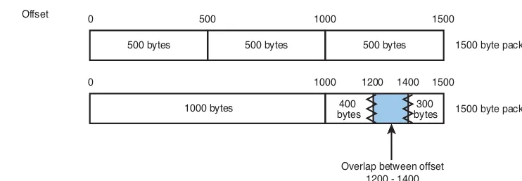
IP provides for a maximum packet size of 65,535 octets, which is much larger than most networks can handle, hence the need for fragmentation. When the first fragment arrives at its destination, the receiving host’s Internet layer starts a reassembly timer; if all fragments are not received by the time a predetermined value is reached, the received fragments are discarded. When fragments are received on time, the receiving host uses the identification field in the IP header to ensure that fragments are inserted back into the correct packet.
This fragmentation method is called Internet fragmentation, and it is documented in the specification for the IP protocol. An intranetfragmentation method is in existence that might be implemented by software developers, but it is outside of RFC specifica-tions. It is a LAN-only method that is transparent to the Internet module in host soft-ware.
Attackers can use altered fragments to allow incoming connections on outgoing-only ports. In 2001, this was exemplified by the Tiny Fragment Attack and the Overlapping Fragment Attack, both of which are explained in RFC 3138, “Protection Against a Variant of the Tiny Fragment Attack.” Do not confuse reassembling fragmented packets with situations where packets unexpectedly arrive out of order. Out-of-order packet arrival is symptomatic of one or more situations that are far more serious than a route through a small packet network. Some of the more worrisome causes for out-of-order packet arrival are
•
Packets have been captured, tampered with, and then played back for intrusion or reconnaissance purposes. An example is a man-in-the-middle (MITM) attack (also called a replay attack).•
Asymmetric routing4is occurring, which, under certain conditions, causesout-of-order packet arrival. For example, when the return path has changed because of a
4Asymmetric routing is when a packet takes a different path on the inbound side of a link than it took on the
circuit failure and the new path has higher propagation delays, an increase in the overall round trip time (RTT) is experienced. This particular condition is known to cause out-of-order packet arrivals.
•
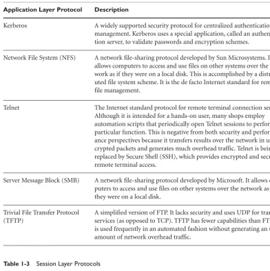
Certain router load-sharing configurations, where the outbound packet stream splits across multiple interfaces, can cause out-of-order packet arrival at the destination.The IPv4 header is specified in RFC 791, “Internet Protocol,” as being six 32-bit words in length when all optional fields are populated and with a minimum value of five words. It has no hardware dependencies and must be compatible with previous versions of IP. The requirement in RFC 791 for compatibility with earlier versions was important at the time because there had been six prior versions in production on ARPANET. This becomes relevant again as IP version 6 (IPv6) becomes a reality on the Internet. Figure 1-6 shows the IPv4 header layout.
Version (4 bits)
0 1 2 3 4 5 6 7 8 9 10 11 12 13 14 15 16 17 18 19 20 21 22 23 24 25 26 27 28 29 30 31 IHL (4 bits)
Identification (16 bits) (3 bits)Flags Fragment Offset (13 bits) Header Checksum (16 bits) Protocol (8 bits)
Source Address (32 bits) Destination Address (32 bits)
Options (variable bit length) Padding (variable bit length) Time to Live (8 bits)
DSCP (6 bits) (2 bits)ECN Total Length (16 bits)
Figure 1-6 IPv4 header layout
A more detailed explanation of an IP packet structure is expounded in the following list. The field name is followed by its length and description:
•
Version Number(4 bits). Contains the IP version of the packet, which is how gate-ways along network paths know how to interpret data in the packet. If the version number is incorrect, the packet is silently discarded, which simply means that no error message is sent.•
Internet Header Length (IHL)(4 bits). Reflects the total length of the IP header built by the sending host. The unit of measure is defined in RFC 791, “Internet Protocol,” as 32-bit words. The minimum value is five.18
Differentiated Services Field (DS Field) in the IPv4 and IPv6 Headers.” A further update, RFC 3168, “The Addition of Explicit Congestion Notification (ECN) to IP,” added Explicit Congestion Notification (ECN), which is the next entry in this list. Differentiated services enable service discrimination by mapping the Differentiated Services Codepoint (DSCP) to a value that changes the treatment of packets by routers in its path. This essentially changes the per hop behavior (PHB).
•
Explicit Congestion Notification (ECN)(2 bits). The bits are used together to indi-cate any of the following status conditions:00. Not ECN-Capable Transport (Not-ECT) 01. ECN-Capable Transport (ECT 1)
10. ECN-Capable Transport (ECT 0). This is the same as ECT 1; implementations may use either.
11. Congestion Experienced (CE)
Equipment manufacturers slowly adopted ECN, but it is now available in most IP devices as a configuration option. Its main benefit is that routers can actually send notifications of congestion instead of simply dropping packets.
•
Total Length(16 bits).5Indicates the total length of the datagram, including the header and data; the unit of measure is octets. The length of the data field can be computed by subtracting the Internet header length from this value. A recommenda-tion is given in RFC 791, “Internet Protocol,” that hosts only send datagrams larger than 576 octets if there is assurance that the receiving end can accept large data-grams. The maximum Internet header length is 60 octets, although the most typical size is 20, which leaves ample room for a considerable amount of data. The liability of sending larger datagrams is that fragmentation can occur.•
Identification(16 bits). Holds an identifying value that is assigned by the sending host. This number is required when reassembling fragmented messages, which ensures that the fragments of one message are not intermixed with other messages.•
Flags (3 bits). Control flags used by the fragmentation process include the following: Bit position 0 is reserved and must be zero.Bit position 1 indicates either may fragment (0) or don’t fragment (1). Bit position 2 indicates last fragment (0) or more fragments (1).
5In keeping with the rest of the list, this is the number of bit positions taken by the Total Length field. It should
Decimal Keyword Protocol Reference
0 HOPOPT IPv6 Hop-by-Hop Option RFC 1883
1 ICMP Internet Control Message RFC 792
2 IGMP Internet Group Management RFC 1112
3 GGP Gateway-to-Gateway RFC 823
4 IP IP in IP (encapsulation) RFC 2003
5 ST Stream RFC 1190 and RFC 1819
6 TCP Transmission Control RFC 793
7 CBT CBT Tony Ballardie
8 EGP Exterior Gateway Protocol RFC888 and David Mills
•
Fragment Offset(13 bits). Indicates where this fragment belongs in the datagram; it is measured in units of 8 octets. This enables IP to reassemble fragmented pack-ets in the proper order.•
Time to Live (TTL)(8 bits). Also called the hop limit. Generally automatically set by the sender and is decremented by 1 at each hop during its journey to the destination node. If the value reaches zero before the datagram reaches its destination, the data-gram, which is probably undeliverable anyway, is discarded. The purpose of the TTL field is to avoid the risk of eternal packets overwhelming the Internet.•
Protocol(8 bits). Identifies the next level protocol in the data portion of the Internet datagram as specified by the Internet Assigned Numbers Authority (IANA) in coordi-nation with the IETF. A list used to be maintained in an RFC, but that was replaced by an online database at http://iana.org. Some examples include the following.20
•
Source IP Address (32 bits). The IP addresses of the sending host.•
Destination IP Address(32 bits). The IP addresses of the receiving host.•
Options(variable length). A mandatory implementation for all IP hosts and gate-ways; transmission of the field is optional. There are two possible use cases: Case 1. One octet as option-type.Case 2. One octet as option-type; one octet as option-length; and a variable amount of option-data octets.
The option-type octet has three fields that convey information:
•
One bit for the copied flag (0 = not copied; 1 = copied).•
Two bits for the option class (0 = control; 1 = future use; 2 = debugging and measurement; 3 = future use).•
Five bits for the option number.There are seven control class(0) options and one debugging and measurement(2) option, as shown in Table 1-6.
Table 1-6 Options
Class Number Length Description
0 0 — End of option list. Occupies one octet and has no length octet.
0 1 — No operation. Occupies one octet and has no length octet.
0 2 11 Security. Carries security, compartmentation,*user group, and handling
restriction codes.
0 3 Variable Loose source routing. Routes datagrams based on information supplied by the source host. Allowed to use any route or number of intermediate gate-ways.
0 9 Variable Strict source routing. Allows no deviations from the specified route. If the route cannot be followed, the datagram is dropped. Strict routing is fre-quently used for testing routes, but rarely for transmission of user datagrams. This is because of the increased chances of the datagram being dropped.
0 7 Variable Record route. Used to trace the datagram route.
0 8 4 Stream ID. Carries the stream identifier.
2 4 Variable Internet timestamp.
•
Padding(variable bits). Padding of zero values to ensure that the header ends on a 32-bit boundary.A
DDRESSINGMoving datagrams through the Internet or through an enterprise network requires the use of three important protocol components: name, address, and route. A name describes the target host; an address identifies where the target is located, usually its physical or logical location in a network; and a route shows how to get there.
In many ways, network addresses are analogous to the addresses that the postal service uses to deliver mail. Both have standard addressing conventions that everyone must use; the source and destination is included, although the postal service is flexible in that regard; there are times when the payload they are associated with is lost along the way. Where networks are concerned,topology, which shows computers and the links between them, is the deciding factor for choosing the correct addressing convention. Topologies are formed over one or more of the following network types: