DISSERTATION RC 14-3505
BEHAVIOR OF REINFORCED CONCRETE
COLUMNS RETROFITTED BY EXTERNAL STEEL
ANGLE COLLARS UNDER AXIAL COMPRESSION
AND COMBINED AXIAL COMPRESSION AND
REVERSED CYCLIC LOADING
NAME : PAMUDA PUDJISURYADI ID NO. : 311 030 1005
SUPERVISOR : PROF. TAVIO, S.T. M.T. PH.D.
CO-SUPERVISOR : PROF. IR. PRIYO SUPROBO, M.S. PH.D.
GRADUATE DIVISION
STRUCTURAL ENGINEERING PROGRAM DEPARTMENT OF CIVIL ENGINEERING
FACULTY OF CIVIL ENGINEERING AND PLANNING SEPULUH NOPEMBER INSTITUTE OF TECHNOLOGY SURABAYA - INDONESIA
iii
BEHAVIOR OF REINFORCED CONCRETE COLUMNS
RETROFITTED BY EXTERNAL STEEL ANGLE COLLARS
UNDER AXIAL COMPRESSION AND COMBINED AXIAL
COMPRESSION AND REVERSED CYCLIC LOADING
Name : Pamuda Pudjisuryadi ID No. : 3110 301 005
Supervisor : Prof. Tavio, S.T. M.T. Ph.D. Co-Supervisor : Prof. Ir. Priyo Suprobo, M.S. Ph.D
ABSTRACT
In reinforced concrete (RC) buildings, damages in columns should be avoided during the earthquakes since they have less ductile inelastic behavior which can lead to proggressive damages and collapse of the structure. Researchers have developed several retrofitting techniques to improve the performance or ductility of RC columns. Concrete jacketing, steel jacketing, external strand prestressing, Fiber Reinforced Polymer (FRP) jacketing, and steel collar jacketing to name a few are among the developed retrofit approaches. In this study, a new retrofitting technique utilizing steel collars as external confinement is proposed. The aim of the study is to develop an effective, yet economical, and practical method to retrofit square, and rectangular, or even elongated RC column sections. Steel angle or L-shapep sections were used as collar elements, which were mounted externally at spacing surrounding the perimeter of the column to enhance the column’s strength, particularly its ductility. To achieve this objective, two phases of experimental program were carried out.
In the first phase of the experimental program, fourteen concrete column specimens were built and tested under monotonic axial compressive load in order to study the impact of the proposed external retrofitting method to the strength and most importantly to the ductility enhancement of the columns. To study this effect, volumetric ratio of confining elements was set as the main parameter. Some stiffening techniques of the collars were also investigated to further examine the potential of the proposed method. The results indicated that the strength, and strain ductility of the retrofitted specimens were enhanced. An analytical model to predict the actual stress-strain curve of the columns confined by external steel angle collars was developed and verified against the experimental stress-strain data. The predictions were in good agreement with the experimental results. The peak stress, strain at peak stress and strains at 50 and 80 percent of the peak stress can be predictied reasonably well.
iv
indicated that the proposed approach can predict with reasonable margins on the conservative side.
In the second phase, five concrete column specimens were cast, and tested under combined axial compression, and quasi-static reversed cyclic lateral load. These tests were intended to investigate the performance of the retrofitted specimens under simulated earthquake load. The enhancement of strength, and ductility which lead to larger energy dissipation capacity are clearly identified. The acceptance criteria set by ACI 374.1-05 is also satisfied. Additionally, a proposed design procedure is also developed based on the limited data obtained from the second phase of the experimental program. The step-by-step design procedure accommodates the need of additional external steel angle collars to retrofit the existing column to improve its ductility. In conclusion, the proposed retrofitting method can be applied as an alternative solution on rehabilitation of seismically deficient square RC columns.
v
PERILAKU KOLOM BETON BERTULANG YANG DIRETROTIT
SECARA EKSTERNAL DENGAN SABUK BAJA SIKU YANG
DIBEBANI AKSIAL TEKAN DAN KOMBINASI BEBAN AKSIAL
TEKAN DAN BEBAN LATERAL SIKLIK
Nama : Pamuda Pudjisuryadi NRP : 3110 301 005
Pembimbing : Prof. Tavio, S.T. M.T. Ph.D. Ko-Pembimbing: Prof. Ir. Priyo Suprobo, M.S. Ph.D.
ABSTRAK
Pada bangunan beton bertulang (BB), kerusakan kolom sebaiknya dihindari saat gempa karena perilaku in-elastis yang kurang daktail pada kolom dapat menyebabkan kerusakan progresif, dan keruntuhan struktur. Para peneliti telah mengembangkan banyak teknik retrofit untuk memperbaiki kinerja atau daktilitas kolom BB. Pembesaran penampang beton, penambahan baja lembaran / cincin, stran eksternal prategang, Fiber Reinforced Polymer (FRP), dan sabuk baja merupakan beberapa metode retrofit yang dikembangkan. Pada penelitian ini, diusulkan sebuah teknik baru menggunakan sabuk baja sebagai pengekang eksternal. Tujuan dari penelitian ini adalah untuk mengembangkan metode retrofit untuk kolom BB bujursangkar, atau bahkan persegi panjang yang efektif, tapi ekonomis, dan praktis / mudah dilaksanakan. Profil baja siku atau L digunakan sebagai elemen sabuk, yang diaplikasikan secara eksternal mengelilingi keliling kolom BB dengan spasi tertentu untuk meningkatkan kekuatan, dan daktilitasnya. Untuk mencapai tujuan ini, dua fase ekperimen dilakukan.
vi
yang dipengaruhi masing-masing. Perbandingan dengan data eksperimen mengindikasikan bahwa pendekatan yang diusulkan dapat memprediksi dengan marjin yang baik pada kecenderungan yang konservatif.
Pada fase kedua, lima spesimen kolom beton dibuat dan diuji dengan kombinasi beban aksial dan lateral siklik bolak-balik quasi-static. Uji ini dilakukan untuk menyelidiki kinerja spesimen yang diretrofit terhadap simulasi beban gempa. Peningkatan kekuatan dan daktilitas yang berujung pada lebih besarnya kapasistas disipasi energi terlihat dengan jelas. Kriteria penerimaan dari ACI 374.1-05 juga terpenuhi. Sebagai tambahan, prosedur perencanaan juga dikembangkan berdasarkan data terbatas yang diperoleh dari eksperimen fase kedua. Prosedur perencanan langkah demi langkah mengakomodasi kebutuhan tambahan sabuk siku baja eksternal dalam meretrofit kolom untuk meningkatkan daktilitasnya. Pada akhirnya, dapat disimpulkan bahwa metode retrofit yang diusulkan dapat dipakai sebagai solusi alternatif pada rehabilitasi kolom BB yang tidak memenuhi persyaratan gempa.
vii
ACKNOWLEDGEMENT
First of all, I would like to praise God for His great blessings that I achieved doctoral degree in the Sepuluh Nopember Institute of Technology. I hope that this dissertation could minimize the loss during earthquake events by enriching retrofitting methods of reinforced concrete columns. I also hope that it provides alternative answer to National demand of upgrading existing deficient reinforced concrete buildings.
I would like to sincerely thank Professor Tavio, my supervisor, and dissertation committee chair, for his wisdom, enthusiasm, inspiration, invalueable guidance, effort, time, and patience in supporting me to complete this dissertation. He has shared his broad knowledge, continuous supports, inspiring ideas, keen supervision, and meticulous revisions tremendously helped me to complete this study. I learned a lot through his rich experience, and his excellent academic, professional, and personal levels.
I would like to extend my gratitude to my co-supervisor Professor Priyo Suprobo, for his priceless advises, time, and supports during my study in Sepuluh Nopember Institute of Technology.
I would also like to thank my committee members, Professor I Gusti Putu Raka, Professor I Nyoman Budiantara, and Professor Adang Surahman for their time in giving valuable input, and constructive suggestions of the dissertation.
Many thanks are also extended to the PETRA Christian University, Surabaya; the place where I have been working as a faculty for more than fifteen years. The supports given for accomplishing my doctoral degree is highly appreciated. I would also like to thank all my colleagues in the University, especially from the Department of Civil Engineering for their warm encouragements, and supports during my study.
The financial supports from Directorate General of Higher Education through the multiyears Program Hibah Kompetisi are also greatly appreciated.
I would like to extend my appreciation, and gratitude to Postgraduate Program of Sepuluh Nopember Institute of Technology, Surabaya, and also Structural Laboratory of Research Center for Human Settlement, Cileunyi, Bandung that provided professional administrative, technical service, and facilities to support study.
viii
ix
TABLE OF CONTENT
TITLE PAGE ... i
APPROVAL PAGE ... ii
ABSTRACT ... iii
ABSTRAK ... v
ACKNOWLEDGEMENT ... vii
TABLE OF CONTENT ... ix
LIST OF TABLES ... xiii
LIST OF FIGURES ... xiv
LIST OF NOTATIONS ... xxxii
CHAPTER 1. INTRODUCTION ... 1
1.1 BACKGROUND ... 1
1.2 RETROFITTING METHODS ... 3
1.3 PROBLEM STATEMENT ... 5
1.4 RESEARCH OBJECTIVES ... 5
1.5 SCOPE OF RESEARCH ... 6
1.6 RESEARCH SIGNIFICANCE ... 7
1.7 STATE OF THE ART... 7
1.8 HYPOTHESIS ... 9
1.9 ORGANIZATION OF DISSERTATION ... 9
CHAPTER 2. THEORETICAL BACKGROUND AND LITERATURE REVIEW ... 11
2.1 GENERAL ... 11
x
2.3 STRESS-STRAIN RELATIONSHIP MODEL OF CONFINED
CONCRETE ... 13
2.4 EXTERNAL CONFINEMENT TECHNIQUES OF REINFORCED CONCRETE COLUMNS ... 35
2.5 STRESS-STRAIN RELATIONSHIP MODEL OF EXTERNALLY CONFINED CONCRETE ... 49
2.6 STRESS STRAIN RELATIONSHIP OF STEEL ... 61
2.7 DUCTILITY ... 62
CHAPTER 3. EXPERIMENTAL PROGRAM ... 67
3.1 INTRODUCTION ... 67
3.2 DESIGN AND DETAILS OF SPECIMENS FOR MONOTONIC - STATIC - AXIAL COMPRESSIVE TEST ... 67
3.3 DESIGN AND DETAILS OF SPECIMENS FOR COMBINED AXIAL COMPRESSIVE AND REVERSED CYCLIC LATERAL LOADING TEST... 83
3.4 MATERIAL MECHANICAL PROPERTIES ... 89
3.5 CONSTRUCTION OF PHASE 1 SPECIMENS ... 90
3.6 CONSTRUCTION OF PHASE 2 SPECIMENS ... 99
3.7 TEST SETUP AND TESTING PROCEDURE ... 104
3.8 SUMMARY ... 113
CHAPTER 4. MONOTONIC AXIAL COMPRESSION TEST (PHASE 1) .... 115
4.1 RESULTS OF THE TEST (PART 1) ... 115
4.2 RESULTS OF THE TEST (PART 2) ... 125
CHAPTER 5. COMBINED AXIAL COMPRESSIVE AND REVERSED CYCLIC LOAD TEST (PHASE 2) ... 131
xi
5.2 ACCEPTANCE CRITERIA ACCORDING TO ACI 374.1-05 ... 150
CHAPTER 6. PROPOSED ANALYTICAL MODEL AND RETROFIT DESIGN APPROACH ... 157
6.1 PROPOSED ANALYTICAL MODEL ... 157
6.2 CALCULATION EXAMPLE OF THE PROPOSED ANALYTICAL PROCEDURE ... 167
6.3 COMPARISON OF PROPOSED ANALYTICAL MODEL WITH EXPERIMENTAL RESULTS OF MONONOTIC COMPRESSION TESTS ... 170
6.4 GENERATED BACKBONES OF HYSTERETIC LOOPS BY PROPOSED ANALYTICAL AXIAL STRESS-STRAIN MODEL 174 6.5 PROPOSED DESIGN PROCEDURE FOR RETROFITTING DEFICIENT SQUARE RC COLUMNS WITH EXTERNAL STEEL COLLAR ... 183
6.6 CALCULATION EXAMPLE OF THE PROPOSED DESIGN RETROFIT APPROACH ... 191
6.7 DISCUSSION 1: MINIMUM AMOUNT OF CONFINING STEEL202 6.8 DISCUSSION 2: COMPARISON WITH OTHER EXTERNAL RETROFITTING METHODS ... 213
CHAPTER 7. CONCLUSIONS AND RECOMMENDATIONS ... 219
7.1 GENERAL FINDINGS... 219
7.2 MONOTONIC COMPRESSION LOAD TEST FINDINGS ... 219
7.3 QUASI-STATIC COMBINED AXIAL COMPRESSION AND REVERSED CYCLIC LATERAL LOAD TEST FINDINGS ... 221
7.4 RECOMMENDATIONS ... 222
xii
APPENDIX A. DATA LOGGER CHANNEL NUMBERS FOR
COMBINED AXIAL COMPRESSIVE AND REVERSED CYCLIC LOAD TEST ... 233 APPENDIX B. RESULTS OF MONONOTIC AXIAL COMPRESSIVE
TEST PART-1 ... 249 APPENDIX C. RESULTS OF MONONOTIC AXIAL COMPRESSIVE
TEST PART-2 ... 275 APPENDIX D. RESULTS OF COMBINED AXIAL COMPRESSIVE
xiii
LIST OF TABLES
Table 1-1 Research on external confinement for retrofitting RC columns ... 8
Table 2-1 Data of collared column specimens (Hussain and Driver, 2005) ... 48
Table 2-2 Data of the column specimens ... 59
Table 2-3 Compressive strength of the specimens ... 59
Table 3-1 Confinement data of experimental specimens (compressive test) ... 81
Table 3-2 The data of experimental specimens (combined lateral and compressive test) ... 89
Table 3-3 Channel numbers data... 112
Table 4-1 Summary of compression test results of Specimens CS01 to S05 ... 116
Table 4-2 Strength gains and failure remarks of Specimens CS01 to S05 ... 120
Table 4-3 Summary of compression test results of Specimens S04a to S04f ... 125
Table 4-4 Strength gain and failure remarks of Specimens S04a to S04f ... 128
Table 5-1 Results of quasi static cyclic combined axial and lateral load test ... 131
Table 5-2 Energy dissipation capacity and deformability of the specimens ... 146
Table 5-3 Initial drift ratios for acceptance criteria according to ACI 374.1-05 151 Table 5-4 Initial displacement for acceptance criteria according to ACI 374.1-05 ... 152
Table 5-5 Observed lateral resistance (push/pull) for Specimen S15 ... 152
Table 5-6 Summary of third criteria of ACI 374.1-05 ... 155
Table 6-1 Concrete forces at all layers ... 182
Table 6-2 Steel forces at longitudinal bars ... 183
Table 6-3 Comparison of performances of external retrofitting methods from literatures ... 217
Table A-1 Channel numbers data of CS11 ... 235
Table A-2 Channel numbers data of CS12 ... 238
Table A-3 Channel numbers data of S13 ... 241
Table A-4 Channel numbers data of S14 ... 244
xiv
LIST OF FIGURES
Figure 1-1 Soft story effect in a typical commercial building (Nias Earthquake, 2005) ... 2 Figure 1-2 Inadequate transverse reinforcement in RC column (Yogyakarta
Earthquake, 2006) ... 2 Figure 1-3 Inadequate columns’ strength in joints (Padang Earthquake, 2009) ... 3 Figure 2-1 Effectively confined concrete area (adopted from Sheikh and Yeh,
1986) ... 12 Figure 2-2 Stress-strain curve proposed by Chan (adopted from Chan et al., 1955) ... 14 Figure 2-3 Stress-strain curve proposed by Roy and Sozen (adopted from Roy and
Sozen, 1965) ... 14 Figure 2-4 Stress-strain curve proposed by Soliman and Yu (adopted from
Soliman and Yu, 1967) ... 15 Figure 2-5 Stress-strain curve proposed by Sargin (adopted from Sargin, 1971) . 15 Figure 2-6 Stress-strain curve proposed by Kent and Park (adopted from Kent and
Park, 1971) ... 16 Figure 2-7 Stress-strain curve proposed by Vallenas et al. (adopted from Vallenas
et al., 1977) ... 16 Figure 2-8 Stress-strain curve proposed by Sheikh and Uzumeri (adopted from
Sheikh and Uzumeri, 1980) ... 17 Figure 2-9 Stress-strain relationship model for plain and confined concrete
subjected to monotonic loading with low strain rate (adopted from Mander et al., 1988a) ... 18 Figure 2-10 Core area in circular section (adopted from Mander et al., 1988a) ... 20 Figure 2-11 Core area in rectangular section (adopted from Mander et al., 1988a) ... 20 Figure 2-12 Lateral stress in a circular section due to confinement (adopted from
Saatcioglu and Razvi, 1992) ... 21 Figure 2-13 Stress-strain relationship of high-strength concrete proposed by Yong
xv
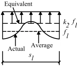
Figure 2-14 Stress-strain curve proposed by Saatcioglu (adopted from Saatcioglu and Razvi, 1992) ... 23 Figure 2-15 Non-unfinorm confining pressure assumed (Modified from Razvi and
Saatcioglu, 1999) ... 24 Figure 2-16 Actual, average, and equivalent confining pressure (adopted from
Razvi and Saatcioglu, 1999) ... 24 Figure 2-17 Stress-strain relationship proposed by Azizinamini et al. (adopted
from Azizinamini et al., 1994) ... 26 Figure 2-18 Stress-strain relationship proposed by Hoshikusuma et al. (adopted
from Hoshikusuma et al., 1997) ... 27 Figure 2-19 Stress-strain relationship proposed by Cusson and Paultre (adopted
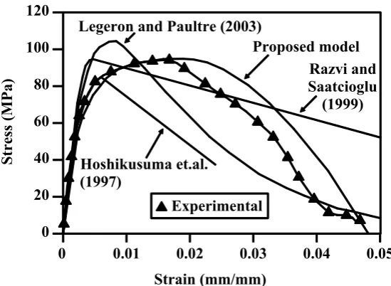
from Cusson and Paultre, 1995) ... 28 Figure 2-20 Stress-strain relationship proposed by Tabsh compared to
experimental data and other models (adopted from Tabsh, 2007) ... 30 Figure 2-21 Stress-strain relationship proposed by Kusuma and Tavio (adopted
from Kusuma and Tavio, 2007) ... 31 Figure 2-22 Stress-strain relationship proposed by Kusuma and Tavio (adopted
from Kusuma and Tavio, 2008) ... 32 Figure 2-23 Comparison of proposed and experimental stress-strain relationship
of: (a) normal concrete; and (b) high strength concrete (Tavio et al., 2008a) .. 34 Figure 2-24 Steel jacket used to retrofit column (courtesy of Chai et al., 1994) .. 36 Figure 2-25 Comparison of hysteretic responses: (a) original column and (b)
retrofitted column (adopted from Chai et al., 1994) ... 36 Figure 2-26 The increase of inertia force due to steel jacket retrofitting method
(adopted from Chai et al., 1994) ... 37 Figure 2-27 Inadequate confinement by rectangular jacket (adopted from
Priestley et al., 1994) ... 38 Figure 2-28 Detail of retrofitted specimens (adopted from Xiao et al., 2003)... 39 Figure 2-29 Prestressed steel jacketing (courtesy of Guo et al., 2006) ... 40 Figure 2-30 Steel sheet jacketing procedure: (a) as-built RC column; (b) apply
xvi
Figure 2-31 FRP sheet jacketing: (a) and (b) apply as strips at certain spacing; (c) apply as continuous sheet (courtesy of Barros et al., 2008) ... 42 Figure 2-32 Failure mechanim of concrete filled: (a) glass FRP tubes; and (b)
carbon FRP tubes (adopted from Saafi et al., 1999) ... 43 Figure 2-33 FRP jacketing method (courtesy of Nesheli et al., 2004) ... 44 Figure 2-34 Columns dimension tested by Carey and Harries (adopted from Carey
and Harries, 2005) ... 44 Figure 2-35 Failure modes of the tested specimens (courtesy of Barros et al.,
2008) ... 45 Figure 2-36 Geometry of the test specimens (adopted from Saatcioglu and Yalcin,
2003) ... 46 Figure 2-37 Hardware used for retrofitting circular columns (adopted from
Saatcioglu and Yalcin, 2003) ... 47 Figure 2-38 Hardware used for retrofitting square columns (adopted from
Saatcioglu and Yalcin, 2003) ... 47 Figure 2-39 Bolted and welded steel HSS collars (courtesy of Hussain and Driver,
2005) ... 48 Figure 2-40 Normalized stress-strain of the specimens (adopted from Hussain and
Driver, 2005) ... 49 Figure 2-41 Plan and elevation view of bolted solid steel collars (courtesy of Liu
et al., 2008) ... 49 Figure 2-42 Simplified stress-strain curves of FRP-encased Concrete (adopted
from Saafi et al., 1999) ... 50 Figure 2-43 Solid concrete cylinder and thin FRP tubes under axial load (adopted
from Fam and Rizkala 2001) ... 52 Figure 2-44 Typical stress-strain relationship of confined concrete (adopted from
Fam and Rizkala 2001) ... 54 Figure 2-45 Typical stress-strain relationship of CFRP confined concrete (adopted
from Barros et al., 2008) ... 55 Figure 2-46 Typical assumed effective confined area (adopted from Lee et al.,
xvii
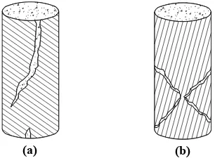
Figure 2-47 Column with (a) 4.82 percent, (b) 12.9 percent, and (c) 25.5 percent volumetric ratio of steel collars ... 58 Figure 2-48 The damage patter of: (a) Column A, (b) Column B, and (c) Column
C ... 59 Figure 2-49 Typical specimen : (a) elevation view, (b) bolted collar, and (c)
welded collar (courtesy of Hussain and Driver, 2005) ... 60 Figure 2-50 Comparison of normalized stress-strain curves for Specimen C02 .. 61 Figure 2-51 Stress strain relationship of steel (adopted from King et al., 1986) .. 61 Figure 2-52 Determination of yield values Qy and y (ACI 374.2R-13) ... 64
Figure 2-53 Cumulative displacement ductility ... 64 Figure 2-54 Ideal Elastoplastic Energy ... 65 Figure 3-1 Elevation view and cross section of Specimens CS01, CS02a, and
CS03a ... 69 Figure 3-2 Elevation view and cross section of Specimen S01 : (a) reinforcement
details ; and (b) external steel collars ... 73 Figure 3-3 Elevation view and cross section of Specimen S02 : (a) reinforcement
details ; and (b) external steel collars ... 74 Figure 3-4 Elevation view and cross section of Specimen S03 : (a) reinforcement
details ; and (b) external steel collars ... 74 Figure 3-5 Elevation view and cross section of Specimen S04 : (a) reinforcement
details ; and (b) external steel collars ... 75 Figure 3-6 Elevation view and cross section of Specimen S05 : (a) reinforcement
details ; and (b) external steel collars ... 75 Figure 3-7 Elevation view and cross section of Specimen S04a : (a) reinforcement
details ; and (b) external steel collars ... 76 Figure 3-8 Elevation view and cross section of Specimen S04b : (a) reinforcement
details ; and (b) external steel collars ... 77 Figure 3-9 Elevation view and cross section of Specimen S04c : (a) reinforcement
details ; and (b) external steel collars ... 78 Figure 3-10 Elevation view and cross section of Specimen S04d : (a)
xviii
Figure 3-11 Elevation view and cross section of Specimen S04e : (a)
reinforcement details ; and (b) external steel collars ... 79
Figure 3-12 Elevation view and cross section of Specimen S04f : (a) reinforcement details ; and (b) external steel collars ... 80
Figure 3-13 Three dimensional illustration of Specimen S03 ... 81
Figure 3-14 Exploded view of Specimen S03 ... 82
Figure 3-15 Top view of Specimen S03 ... 82
Figure 3-16 Elevation view of Specimen S03 ... 83
Figure 3-17 Elevation view and cross section of Specimen CS11 : (a) transverse to lateral load direction ; (b) in lateral load direction ... 85
Figure 3-18 Elevation view and cross section of Specimen CS12 : (a) transverse to lateral load direction ; (b) in lateral load direction ... 86
Figure 3-19 Elevation view and cross section of Specimen S13 : (a) transverse to lateral load direction ; (b) in lateral load direction ... 87
Figure 3-20 Elevation view and cross section of Specimen S14 : (a) transverse to lateral load direction ; (b) in lateral load direction ... 88
Figure 3-21 Elevation view and cross section of Specimen S15 : (a) transverse to lateral load direction ; (b) in lateral load direction ... 89
Figure 3-22 The packing and strain gauge used ... 91
Figure 3-23 Flattened and smoothened surface of bars prior to the attachment of strain gauges ... 91
Figure 3-24 The strain gauges attached to the bars by using provided adhesive .. 92
Figure 3-25 The strain gauges were protected by provided coating... 92
Figure 3-26 Typical placing of strain gauges on longitudinal and transversal bars in the test region ... 92
Figure 3-27 Typical placing of strain gauges on steel angle collars ... 93
Figure 3-28 Formworks used for the specimens ... 94
Figure 3-29 A sample of reinforcement cage (e.g. Specimen S04) ... 94
Figure 3-30 A sample of reinforcement cage with installed coded strain gauges (e.g. Specimen CS02a) ... 94
xix
Figure 3-32 Pozzolanic Portland Cement ... 95
Figure 3-33 Lumajang sand used in the concrete mix ... 95
Figure 3-34 Coarse aggregate (crushed stones) used in the concrete mix ... 96
Figure 3-35 Concrete mixing process ... 96
Figure 3-36 Concrete placing by using hand shovel ... 96
Figure 3-37 Vibrated concrete to minimize trapped bubbles ... 97
Figure 3-38 Molded specimens and standard cylinders ... 97
Figure 3-39 Curing of standard cylinders ... 98
Figure 3-40 Cover of specimens to prevent direct sunlight ... 98
Figure 3-41 Externally collared column specimens ... 99
Figure 3-42 Prepared formworks and reinforcements of the specimens... 100
Figure 3-43 Reinforcement of typical footing of the specimens... 100
Figure 3-44 Reinforcement of column head ... 101
Figure 3-45 Concrete casting of foundation... 101
Figure 3-46 Concrete compacting of foundation ... 102
Figure 3-47 Concrete compacting of column... 102
Figure 3-48 Concrete casting of standar cylinder ... 103
Figure 3-49 Steel plate of column head ... 103
Figure 3-50 The five column specimens for quasi-static combined axial and cyclic lateral load test ... 104
Figure 3-51 Compression test setup (static monotonic) ... 105
Figure 3-52 Four load cells with 50 ton capacity each ... 106
Figure 3-53 Typical axial compressive test set-up ... 106
Figure 3-54 Real time on screen display during the test ... 107
Figure 3-55 Combined axial compressive and reversed cyclic lateral load test . 108 Figure 3-56 Sequence of lateral displacement used in the test (ACI 374.1-05) . 108 Figure 3-57 Typical setup for combined axial compressive and reversed cyclic lateral load test ... 109
Figure 3-58 Data logger channel numbers : (a) East view / Side 1; (b) South view / Side 2; (c) West view / Side 3; and (d) North view / Side 4 ... 110
xx
Figure 4-1 Normalized stress-strain curves of control and collared specimens .. 119
Figure 4-2 Column axial stress-longitudinal bar axial strain curves of CS01 ... 121
Figure 4-3 Column axial stress-stirrups strain curves of CS03a ... 122
Figure 4-4 Column axial stress-steel collar axial strain curves of S05 (Collar 3) ... 122
Figure 4-5 Collar 3 of S05 after the completion of the test ... 123
Figure 4-6 Specimens: (a) CS01; (b) CS02a; and (c) CS03a after the completion of the tests ... 123
Figure 4-7 Specimens: (a) S01; (b) S02; and (c) S03 after the completion of the tests ... 124
Figure 4-8 Specimens: (a) S04; and (b) S05 after the completion of the tests .... 124
Figure 4-9 Normalized stress-strain curves of collared Specimens S04 to S04f . 126 Figure 4-10 Steel collars of Specimens S04a, S04b, S04c, S04d, S04e, and S04f after completion of the tests ... 129
Figure 4-11 Specimens S04a, S04b, S04c, S04d, S04e, and S04f after completion of the tests ... 130
Figure 5-1 Hysteretic lateral force-displacement curve of CS11 ... 133
Figure 5-2 Hysteretic lateral force-displacement curve of CS12 ... 133
Figure 5-3 Hysteretic lateral force-displacement curve of S13 ... 134
Figure 5-4 Hysteretic lateral force-displacement curve of S14 ... 134
Figure 5-5 Hysteretic lateral force-displacement curve of S15 ... 135
Figure 5-6 Hysteretic bending moment – curvature curve of CS11 ... 136
Figure 5-7 Hysteretic bending moment - curvature curve of CS12 ... 137
Figure 5-8 Hysteretic bending moment – curvature curve of S13 ... 137
Figure 5-9 Hysteretic bending moment – curvature curve of S14 ... 138
Figure 5-10 Hysteretic bending moment – curvature curve of S15 ... 138
Figure 5-11 Specimens: (a) CS11; and (b) CS12 after the completion of the tests ... 139
Figure 5-12 Specimens: (a) S13; (b) S14; and (c) S15 after the completion of the tests ... 140
xxi
Figure 5-15 Hysteretic lateral loap-longitudinal bar axial strain curve of CS12 142
Figure 5-16 Hysteretic lateral load-stirrups axial strain curve of CS12... 142
Figure 5-17 Hysteretic lateral load-steel collar axial strain of S13 ... 143
Figure 5-18 Hysteretic lateral load-steel collar axial strain of S14 ... 144
Figure 5-19 Hysteretic lateral load-steel collar axial strain of S15 ... 144
Figure 5-20 Steel collars nearest to fixity points (column footings) of Specimens : (a) S13; (b) S14; and (c) S15 after the completion of the test ... 145
Figure 5-21 Cumulative dissipation energy vs loading cycle ... 147
Figure 5-22 Cumulative displacement ductility vs loading cycle ... 147
Figure 5-23 Cumulative curvature ductility vs loading cycle ... 148
Figure 5-24 Hysteretic lateral load vs vertical movement of CS11 footing ... 149
Figure 5-25 Hyteretic lateral load vs horizontal movement of CS11 footing ... 149
Figure 5-26 Energy dissipation capacity of Specimen S15 ... 154
Figure 5-27 Secant stiffnesses of Specimen S15 ... 154
Figure 6-1 Perspective view of the illustration of the externally confined column specimen with steel collars ... 158
Figure 6-2 Non-uniform confining stress of square column section externally retrofitted by steel collars ... 158
Figure 6-3 The parabolic-shaped ineffectively confined region at: (a) cross section and (b) along the height of the column ... 159
Figure 6-4 The effective equivalent uniform confining stress ... 160
Figure 6-5 Linear relationship of peak strength and effective uniform confining pressure ... 161
Figure 6-6 Relationship of normalized peak strength and the normalized corresponding strain ... 162
Figure 6-7 (a) Bulged steel collars due to lateral expansion of axially loaded concrete column, and (b) equilibrium of forces analyzed at a quarter of the cross section ... 163
Figure 6-8 Flowchart of the step-by-step proposed procedure ... 165
xxii
Figure 6-11 Normalized stress vs axial strain of proposed analytical model and experimental results of S02 ... 172 Figure 6-12 Normalized stress vs axial strain of proposed analytical model and
experimental results of S04, S04c, and S04d ... 173 Figure 6-13 Normalized stress vs axial strain of proposed analytical model and
experimental results of S04e, and S04f ... 173 Figure 6-14 Descretization of RC section ... 174 Figure 6-15 Strains and stresses due to initial axial force P0 ... 175
Figure 6-16 Strain and stress distributions across the sectional depth with the application of the incremental strain () over the initial strains ... 176 Figure 6-17 Predicted backbone of M- curve of Specimen S13 ... 177 Figure 6-18 Predicted backbone of M- curve of Specimen S14 ... 178 Figure 6-19 Predicted backbone of M- curve of Specimen S15 ... 178 Figure 6-20 Effectively confined areas due to the internal and external
confinements ... 185 Figure 6-21 Flowchart of the proposed retrofit design approach ... 186 Figure 6-22 Relationship of flexural strength increment and confinement index190 Figure 6-23 Relationship of curvature ductility and confinement index ... 190 Figure 6-24 Confinements of Specimen S04a : (a) internal; and (b) external ... 192 Figure 6-25 Stress-strain relationship of S04a (retrofit design approach) ... 196 Figure 6-26 Normalized stress vs axial strain of combined effect of internal and
external confinement and experimental results of Specimens S04a and S04b ... 200 Figure 6-27 Performances (stress-strain curve) of deficient and targeted RC
columns ... 201 Figure 6-28 Performance (stress-strain curves) of deficient and targeted RC
columns (first trial) ... 201 Figure 6-29 Performance (stress-strain curves) of deficient and targeted RC
columns (final attempt) ... 202 Figure A-1 Data logger channel numbers of Specimen CS11 : (a) East view / Side
xxiii
Figure A-2 Locations of each data logger channel of Specimen CS11 : (a) East view / Side 1; (b) South view / Side 2; (c) West view / Side 3; and (d) North view / Side 4 ... 234 Figure A-3 Data logger channel numbers of Specimen CS12 : (a) East view / Side
1; (b) South view / Side 2; (c) West view / Side 3; and (d) North view / Side 4 ... 236 Figure A-4 Locations of each data logger channel of Specimen CS12 : (a) East
view / Side 1; (b) South view / Side 2; (c) West view / Side 3; and (d) North view / Side 4 ... 237 Figure A-5 Data logger channel numbers of Specimen S13 : (a) East view / Side
1; (b) South view / Side 2; (c) West view / Side 3; and (d) North view / Side 4 ... 239 Figure A-6 Locations of each data logger channel of Specimen S13 : (a) East view
/ Side 1; (b) South view / Side 2; (c) West view / Side 3; and (d) North view / Side 4 ... 240 Figure A-7 Data logger channel numbers of Specimen S14 : (a) East view / Side
1; (b) South view / Side 2; (c) West view / Side 3; and (d) North view / Side 4 ... 242 Figure A-8 Locations of each data logger channel of Specimen S14 : (a) East view
/ Side 1; (b) South view / Side 2; (c) West view / Side 3; and (d) North view / Side 4 ... 243 Figure A-9 Data logger channel numbers of Specimen S15 : (a) East view / Side
1; (b) South view / Side 2; (c) West view / Side 3; and (d) North view / Side 4 ... 245 Figure A-10 Locations of each data logger channel of Specimen S15 : (a) East
view / Side 1; (b) South view / Side 2; (c) West view / Side 3; and (d) North view / Side 4 ... 246 Figure B-1 Column axial stress-strain curves of CS01 ... 249 Figure B-2 Column axial stress-longitudinal bar axial strain curves of CS01 .... 249 Figure B-3 Specimen CS01: (a) side 1; and (b) side 2 after the completion of the
xxiv
Figure B-4 Specimen CS01: (a) side 3; and (b) side 4 after the completion of the test ... 250 Figure B-5 Column axial stress-strain curves of CS02a ... 251 Figure B-6 Column axial stress-longitudinal bar axial strain curves CS02a ... 251 Figure B-7 Column axial stress-stirrups axial strain curves of CS02a ... 252 Figure B-8 Specimen CS02a: (a) side 1; and (b) side 2 after the completion of the
test ... 252 Figure B-9 Specimen CS02a: (a) side 3; and (b) side 4 after the completion of the
test ... 253 Figure B-10 Column axial stress-strain curves of CS03a ... 253 Figure B-11 Column axial stress-longitudinal bar axial strain curves of CS03a 254 Figure B-12 Specimen CS03a: (a) side 1; and (b) side 2 after the completion of
the test ... 254 Figure B-13 Specimen CS03a: (a) side 3; and (b) side 4 after the completion of
the test ... 255 Figure B-14 Column axial stress-strain curves of S01 ... 255 Figure B-15 Column axial stress-longitudinal bar axial strain curves of S01 ... 256 Figure B-16 Column axial stress-steel collar axial strain curves of S01 (Collar 1
Side 1) ... 256 Figure B-17 Column axial stress-steel collar axial strain curves of S01 (Collar 1
Side 2) ... 257 Figure B-18 Specimen S01: (a) side 1; and (b) side 2 after the completion of the
test ... 257 Figure B-19 Specimen S01: (a) side 3; and (b) side 4 after the completion of the
xxv
Figure B-25 Specimen S02 after the completion of the test ... 261 Figure B-26 Specimen S02: (a) side 1; and (b) side 2 after the completion of the
test ... 261 Figure B-27 Specimen S02: (a) side 3; and (b) side 4 after the completion of the
test ... 262 Figure B-28 Collars: (a)1; and (b)2 of S02 after the completion of the test ... 262 Figure B-29 Column axial stress-strain curves of S03 ... 263 Figure B-30 Column axial stress-longitudinal bar axial strain curves of S03 .... 263 Figure B-31 Column axial stress-steel collar axial strain curves of S03 (Collar 1) ... 264 Figure B-32 Column axial stress-steel collar axial strain curves of S03 (Collar 2) ... 264 Figure B-33 Specimen S03: (a) side 1; and (b) side 2 after the completion of the
test ... 265 Figure B-34 Specimen S03: (a) side 3; and (b) side 4 after the completion of the
test ... 265 Figure B-35 Collars: (a) 1; and (b) 2 of S03 after the completion of the test ... 266 Figure B-36 Collar 3 of S03 after the completion of the test ... 266 Figure B-37 Column axial stress-strain curves of S04 ... 267 Figure B-38 Column axial stress-longitudinal bar axial strain curves of S04 .... 267 Figure B-39 Column axial stress-steel collar axial strain curves of S04 (Collar 2) ... 268 Figure B-40 Column axial stress-steel collar axial strain curves of S04 (Collar 3) ... 268 Figure B-41 Specimen S04: (a) side 1; and (b) side 2 after the completion of the
test ... 269 Figure B-42 Specimen S04: (a) side 3; and (b) side 4 after the completion of the
xxvi
Figure B-47 Column axial stress-steel collar axial strain curves of S05 (Collar 2) ... 272 Figure B-48 Specimen S05: (a) side 1; and (b) side 2 after the completion of the
test ... 272 Figure B-49 Specimen S05: (a) side 3; and (b) side 4 after the completion of the
test ... 273 Figure B-50 Collars: (a) 1; and (b) 2 of S05 after the completion of the test ... 273 Figure B-51 Collars: (a) 3; and (b) 4 of S05 after the completion of the test ... 274 Figure B-52 Collar 5 of S05 after the completion of the test ... 274 Figure C-1 Column axial stress-strain curves of S04a ... 275 Figure C-2 Column axial stress-longitudinal bar axial strain curves of S04a ... 275 Figure C-3 Column axial stress-stirrups axial strain curves of S04a ... 276 Figure C-4 Column axial stress-steel collar axial strain curves of S04a (Collar 2) ... 276 Figure C-5 Column axial stress-steel collar axial strain curves of S04a (Collar 3) ... 277 Figure C-6 Specimen S04a: (a) side 1; and (b) side 2 after the completion of the
test ... 277 Figure C-7 Specimen S04a: (a) side 3; and (b) side 4 after the completion of the
test ... 278 Figure C-8 Collars: (a) 1; and (b) 2 of S04a after the completion of the test ... 278 Figure C-9 Collars: (a) 3; and (b) 4 of S04a after the completion of the test ... 279 Figure C-10 Column axial stress-strain curves of S04b ... 279 Figure C-11 Column axial stress-longitudinal bar axial strain curves of S04b ... 280 Figure C-12 Column axial stress-stirrups axial strain curves of S04b ... 280 Figure C-13 Column axial stress-steel collar axial strain curves of S04b (Collar 2) ... 281 Figure C-14 Column axial stress-steel collar axial strain curves of S04b (Collar 3) ... 281 Figure C-15 Specimen S04b: (a) side 1; and (b) side 2 after the completion of the
xxvii
Figure C-16 Specimen S04b: (a) side 3; and (b) side 4 after the completion of the test ... 282 Figure C-17 Collars: (a) 1; and (b) 2 of S04b after the completion of the test ... 283 Figure C-18 Collars: (a) 3; and (b) 4 of S04b after the completion of the test ... 283 Figure C-19 Column axial stress-strain curves of S04c ... 284 Figure C-20 Column axial stress-longitudinal bar axial strain curves of S04c... 284 Figure C-21 Column axial stress-steel collar axial strain curves of S04c (Collar 2) ... 285 Figure C-22 Column axial stress-steel collar axial strain curves of S04c (Collar 3) ... 285 Figure C-23 Specimen S04c: (a) side 1; and (b) side 2 after the completion of the
test ... 286 Figure C-24 Specimen S04c: (a) side 3; and (b) side 4 after the completion of the
test ... 286 Figure C-25 Collars: (a) 1; and (b) 2 of S04c after the completion of the test ... 287 Figure C-26 Collars: (a) 3; and (b) 4 of S04c after the completion of the test ... 287 Figure C-27 Column axial stress-strain curves of S04d ... 288 Figure C-28 Column axial stress-longitudinal bar axial strain curves of S04d .. 288 Figure C-29 Column axial stress-steel collar axial strain curves of S04d (Collar 2) ... 289 Figure C-30 Column axial stress-steel collar axial strain curves of S04d (Collar 3) ... 289 Figure C-31 Specimen S04d: (a) side 1; and (b) side 2 after the completion of the
test ... 290 Figure C-32 Specimen S04d: (a) side 3; and (b) side 4 after the completion of the
xxviii
Figure C-38 Column axial stress-steel collar axial strain curves of S04e (Collar 3) ... 293 Figure C-39 Specimen S04e: (a) side 1; and (b) side 2 after the completion of the
test ... 294 Figure C-40 Specimen S04e: (a) side 3; and (b) side 4 after the completion of the
test ... 294 Figure C-41 Collars: (a) 1; and (b) 2 of S04e after the completion of the test .... 295 Figure C-42 Collars: (a) 3; and (b) 4 of S04e after the completion of the test .... 295 Figure C-43 Column axial stress-strain curves of S04f ... 296 Figure C-44 Column axial stress-longitudinal bar axial strain curves of S04f ... 296 Figure C-45 Column axial stress-steel collar axial strain curves of S04f (Collar 2) ... 297 Figure C-46 Column axial stress-steel collar axial strain curves of S04f (Collar 3) ... 297 Figure C-47 Specimen S04f: (a) side 1; and (b) side 2 after the completion of the
test ... 298 Figure C-48 Specimen S04f: (a) side 3; and (b) side 4 after the completion of the
xxix
xxx
xxxi
xxxii
LIST OF NOTATIONS
c
A : gross area of confined concrete core (for proposed method) cc
A : net area of confined concrete core ce
A : gross area of confined concrete core influenced by external confinement ci
A : gross area of confined concrete core influenced by internal confinement cce
A : net area of confined concrete core influenced by external confinement cci
A : net area of confined concrete core influenced by internal confinement ch
A : cross section area of column measured from the outside edges of transverse reinforcement
e
A : area of effectively confined concrete core (for proposed method, and Mander et al., 1988a, 1988b)
ee
A : area of effectively confined concrete core influenced by external confinement
ei
A : area of effectively confined concrete core influenced by internal confinement
g
A : gross area of concrete column section l
A : total area of longitudinal bars par
A : ineffectively confined area (for proposed method) s
A : area of confinement steel in x/y direction in rectangular concrete column min
v
A : minimum area of stirrups sc
A : area of steel angle section
B : dimension of rectangular concrete column (for Lee et al., 2010)
b : dimension of square concrete column (for proposed method); length of flat side of camfered rectangular concrete column (for Lee et al., 2010) c
xxxiii w
b : width of concrete element
1,2
c : coefficients (for proposed method) y
c : core dimension (for Paultre and Legeron, 2008) d
C : coefficient which depends on ductility level of the moment resisting frame system (International Building Code 2000)
i
C : size of WWF cell (for Kusuma and Tavio, 2007) d : diameter of column (for Saafi et al., 1999)
c
d : diameter of WWF reinforcement (for Kusuma and Tavio, 2007) ac
E : actual dissipation energy id
E : ideal dissipation energy c
E : modulus of elasticiy of concrete des
E : deterioration rate of descending branch of stress-strain realtionship curve n
E : lateral resistance sec
E : secant modulus of elasticity of confined concrete sece
E : secant stiffness of concrete due to external confinement seci
E : secant stiffness of concrete due to internal confinement 0
f : peak stress of confined concrete (for Azizinamini et al., 1994) c
f : compressive strength of concrete ce
f : compressive strength of concrete do to external confinement ci
f : compressive strength of concrete do to internal confinement .
c uc
f : axial stress of uneffectice confined area (for Lee et al., 2010) .
cc e
f : axial stress of effectice confined area (for Lee et al., 2010) com
xxxiv h
f : stress at transverse steel (for Legeron and Paultre, 2003) h
f : average lateral confining pressure lcomb
f : uniform lateral confining pressure due to combined internal and external confinement
le
f : equivalent uniform lateral confining pressure due to external confinement li
f : uniform lateral confining pressure due to internal confinement
,
lx y
f : average lateral confining pressure in x,y directions s
f : stress in steel (for King et al., 1986) su
f : ultimate stress in steel (King et al., 1986) y
f : yield strength of longitudinal steel yh
f : yield strength of transversal steel (for Hoshikusuma et al., 1997) ysc
f : yield strength of steel angle section yt
f : yield strength of transversal steel c
f : compressive strength of standard concrete cylinder 0
c
f : compressive strength of unconfined concrete
cc
f : compressive strength of confined concrete
cccomb
f : compressive strength of confined concrete due to combined internal and
external confinement cce
f : compressive strength of confined concrete due to external confinement
cci
f : compressive strength of confined concrete due to internal confinement
h
f : effective stress at transverse steel (for Paultre and Legeron, 2008)
l
f : effective lateral confining pressure
t
f : tensile strength of concrete
CPC cc
f : strength of confined plain concrete (for Barros et al., 2008) h : dimension of rectangular concrete column
h : width of confined core (for Yong et al., 1988) sc
h : height of steel angle section x
xxxv
H : dimension of rectangular concrete column (for Lee et al., 2010) e
I : effective confinement index
k : effective length factor
1,2,3,4
k : coefficients (for Razvi and Saatcioglu, 1999) e
k : confinement effectiveness factor f
k : coefficient (for Paultre and Legeron, 2008) ee
k : confinement effectiveness factor due to external confinement ei
k : confinement effectiveness factor due to internal confinement n
k : coefficient (for Paultre and Legeron, 2008) p
k : ratio of applied axial load with respect to nominal axial capacity of column
K : initial stiffness of hysteretic loop (push mode) K : initial stiffness of hysteretic loop (pull mode)
e
K : initial effective stiffness h
K : coefficient of effectiveness factor in horizontal direction sec
K : secant stiffness of hysteretic loop (push mode) sec
K : secant stiffness of hysteretic loop (pull mode) v
K : coefficient of effectiveness factor in vertical direction u
L : unbraced length of column
m
: bending moment of steel collar (for proposed method), coefficient (for Tabsh, 2007), coefficient (for King et al., 1986)n
m : nominal bending moment capacity of steel collar (proposed method) max
M : maximum bending moment resistance
n
: number of longitudinal bars (for Yong et al., 1988), coefficient (for Hoshikusuma, 1997)l
n : number of longitudinal bars (for proposed method) N : cumulative displacement ductility factor
N : cumulative curvature ductility factor
xxxvi n
p : nominal axial force capacity of steel collar (proposed method) 0
P : theoretical nominal axial capacity
0c
P : theoretical nominal axial capacity contributed by concrete
0cc
P : theoretical nominal axial capacity contributed by concrete core cmax
P : maximum axial resistance contributed by concrete max
P : maximum axial resistance; maximum lateral resistance y
Q : maximum strength (ACI 374.2R-13)
R : radius of concrete cylinder
r : radius of camfered corner of rectangular concrete column (for Lee et al., 2010), coefficient (for Mander et al., 1988), radius of gyration,
coefficient (for King et al., 1986) comb
r : coefficient for generating axial stress-strain curve due to combined internal and external confinement
e
s
: center-to-center spacing of stirrupss : clear spacing of stirrups sc
s : center-to-center spacing of steel collar (for proposed method) scc
s : clear spacing of steel collar (for proposed method) f
TE : total cumulative energy up to failure of specimen 80
TE : total cumulative energy up to 20 percent decay of strength N
TE : TE80 normalized by ideal elastoplastic energy t : thickness of Fibre Reinforced Polymer (FRP)
sc
t : thickness of steel angle section R
u : radial displacement c
w : unit weight of concrete (kgf/m3)
sc
w : width of steel angle section i
xxxvii
Z : plastic modulus of steel angle section
: coefficient (for Hoshikusuma, 1997) : coefficient (for Hoshikusuma, 1997) a
: allowable displacement max
: maximum lateral displacement y
: yield axial displacement; yield lateral displacement u
: ultimate axial displacement; ultimate lateral displacement 0
: strain corresponding to f0 (for Azizinamini et al., 1994) 01 : axial strain corresponding to fc0 1
: strain corresponding to fcc (for Saatcioglu and Razvi, 1992)85
: axial strain at 0.85 fcc on descending branch
b
: strain of concrete (for Sargin, 1971) c
: strain at transition zone of carbon FRP (for Barros et al. 2008) cu
: ultimate compressive strain of concretexxxviii h
: strain of transverse steel s
: strain of steel (for King et al., 1986) sh
: strain at start of steel hardening (for King et al., 1986) spall : strain at concrete start spalling su
: ultimate strain of steel (for King et al., 1986) t
: ultimate tensile strain of concrete Pmax
: strain of concrete corresponding to Pmax cc : ultimate strain of confined plain concrete (for Barros et al., 2008)
: reduction factor (proposed method) l
: diameter of longitudinal steel s : diameter of lateral steel
: curvature max
: maximum curvature y
: yield curvature u
: ultimate curvature
: ratio of column nominal bending capacity with respect to beam nomimal bending capacity
: displacement ductility factor
: axial strain ductility factor a
: absolute axial strain ductility factor : curvature ductility; ductility demand c
: Poisson’s ratio of concrete sxxxix
: ratio of longitudinal bars with respect to gross concrete area c
: area ratio of lateral steel f : volumetric ratio of carbon FRP (for Barros et al., 2008) s
: volumetric ratio of lateral steel R
: radial pressure s
xl
1
CHAPTER 1.
INTRODUCTION
1.1 BACKGROUND
With the development of knowledge on seismic action (resulting in codes specifying higher seismic demand), many existing reinforced concrete (RC) structures are in need of strengthening and retrofitting. Typically, according to Liu et al. (2008), the resulting deficiencies that often characterize old existing RC frame structures include: (1) insufficient transverse reinforcement to confine the column core and to restrain buckling of longitudinal reinforcement; (2) inadequate lap splices located immediately above floor levels where inelastic actions may be concentrated with large flexural demand; (3) insufficient shear strength to develop the column flexural capacity, or the potential degradation of column shear strength with increasing flexural ductility demand; (4) inadequate column strength to develop a strong-column weak-beam mechanism, and (5) deficient beam-to-column joint dimensions and details. These situations are worsen when combined with the existing RC structure conditions that were designed and built with no technical assistance (non-engineered buildings) commonly found in most residential houses in Indonesia. Thus, strengthening and retrofitting of existing RC structures has urgently become a national demand.
2
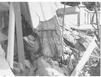
inadequate transverse reinforcement during the 2006 Yogyakarta Earthquake. Figure 1-3 shows the joints in RC structures which were not designed properly leading to the plastic hinge formations in columns instead of beams (Padang Earthquake, 2009).
Figure 1-1 Soft story effect in a typical commercial building (Nias Earthquake, 2005)
3
Figure 1-3 Inadequate columns’ strength in joints (Padang Earthquake, 2009)
Mander et al. (1988a, 1988b) mentioned that the most important thing in plastic hinge design of reinforced concrete columns is the availability of sufficient transverse reinforcement for confining the concrete, preventing the buckling of longitudinal reinforcement, and avoiding brittle shear failure. In order to provide such requirement in existing deficient RC columns, retrofitting purpose should be introduced.
1.2 RETROFITTING METHODS
4
and Manni, 1999), or steel collar jacketing (Chapman and Driver, 2006; Hussain and Driver, 2005; Liu et al., 2008). All methods except concrete jacketing can also be improved by applying external prestressing force (Choi et al., 2010; Guo et al., 2006; Nesheli et al., 2004; Saatcioglu et al., 2003).
Ideally, an effective retrofitting technique shall possess such characteristics as being easy to implement, minimizing disruption to the use of the structure, not requiring highly specialized skills, minimizing labour costs, and resulting in efficient performance (Liu et al., 2008). Concrete and steel jacket are very effective but inconvenient to install, because doing so requires using scaffolds for curing the concrete or grout (Choi et al., 2010). FRP jackets have several advantages over the steel and concrete jackets: (1) ease of installation; (2) no increment of the cross section; and (3) no increment of the flexural or shear stiffness of the structure. However, FRP jacketing is generally uneconomical compared with the concrete and steel jacketings (Choi et al., 2010). Chapman and Driver (2006) developed a retrofitting technique by using steel collars cut from steel plates which were installed with high strength bolts. The method has been proven to be quite effective. The ease of installation which does not require any grouting or welding effort has made the method very promising for further research.
5
test and quasi static combined compressive and reversed cyclic loading test. An analytical model to predict axial compressive stress-strain relationship and a retrofit design procedure are also developed with very good comparisons with the experimental results.
1.3 PROBLEM STATEMENT
The current study is aimed to further investigate the feasibility of steel collar jacketing method for retrofitting seismically deficient square RC columns. Instead of heavier steel sections (hollow square sections and relatively thick plates used in previous researches by others), the economical and very light angle section commonly used for roof truss structures is chosen for making the steel collar module. Due to the lighter and relatively weaker steel angle sections, some issues that may arise and need to be investigated are as follows:
How is the effectiveness of the proposed external retrofit method for RC columns by using steel angle collars in terms of strength and ductility enhancements ?
How to analytically predicts the axial stress-strain relationship of square RC columns retrofitted with the steel angle collars ?
How is the retrofit design approach of existing deficient square RC columns retrofitted by the steel angle collars ?
1.4 RESEARCH OBJECTIVES
The overall goal of the study is to investigate the feasibility of the proposed retrofitting method for seismic deficient square RC columns. In general, it is expected to contribute in solving the national demand on strengthening and retrofitting the old and existing seismic deficient or non-seismic designed RC structures. The specific objectives ofn the study are as follows:
6
To provide a proposed analytical method in predicting the axial stress-strain relationship of square RC columns retrofitted with the external steel collars.
To come up with a proposed design procedure for retrofitting the existing seismic deficient or non-seismic designed square RC columns.
1.5 SCOPE OF RESEARCH
In order to effectively achieve the objectives, the scope of research should be determined. The followings are the items listed as the scope of research:
Among available retrofitting techniques, external retrofit is selected due to its practical application.
In order to rule out the possible effect of slenderness, the experiment is mainly focused on non-slender columns (column specimens were all set to have the shear span to depth ratio not greater than 3.0).
Steel angle section is selected for the steel collar confinement elements due to its economical value and high availability in the market.
The study only focuses on retrofitting square concrete columns.
Normal strength concrete is used for representing widely used concrete strength in Indonesia, particularly in the past when high strength concrete was not yet used for non-seismic designed (seimic deficient) building structures.
The experimental tests are limitted to: (1) monotonic static compression loading; and (2) combined quasi-static axial compression and reversed cyclic lateral loading.
The external steel collars used for retrofit are installed at zero stress state of the specimens.
7
Enhancement in strength and ductility are defined as the performance of the proposed method.
Volumetric ratio of steel angle collars with respect to concrete or spacing of steel angle collars (since only one section size is used in the study) and stiffeners of steel angle collars (web stiffeners and strucutral bolts) are the independent variables in the study.
1.6 RESEARCH SIGNIFICANCE
The research will have significant contributions in:
Enriching retrofit methods of square RC columns.
Solving a national demand by providing an economical, efficient, and practical alternative solutions for retrofitting the existing seismic deficient or non-seismic designed square RC columns.
1.7 STATE OF THE ART
8
Table 1-1 Research on external confinement for retrofitting RC columns
Confinement
Method Circular Column Rectangular Square /
Column
External
Prestressing Axial Load Combined Axial and
Lateral
Jacketing Hussain et al., 2005;
Chapman et
The proposed method have several advantages over the others, as follows : a. Ecomonical value
The use of lighter steel angle sections over heavier elements used by other researchers (e.g. thick steel plates, hollow square sections) provides more economical alternative solution. The practical preparation and implementation can save time and also cut the cost.
b. Easy to prepare and apply
9
proposed system does not require any special labor skill and devices, or even grouting material.
The proposed study is expected to contribute an alternative external retrofitting method (member-level approach). The primary difference of the proposed method compared to available steel collar jacketing method is in term of the steel section used. Available angle steel section in the market is used instead of manually fabricated from thick steel plates. All of these improve the applicability and practicability of the proposed method.
1.8 HYPOTHESIS
Some parameters should be given extra attentions, in order to gain the optimum effectiveness of the proposed method. The connections between steel collar elements at the corners should have good strength and the interactions between the surface of concrete and steel angle collars should be effectively in full contact. If developed properly, the proposed external retrofitting method using steel angle collars should provide sufficient confinement effect which leads to the enhancement of strength and ductility of seismic deficient square RC columns.
1.9 ORGANIZATION OF DISSERTATION
10
11
CHAPTER 2.
THEORETICAL BACKGROUND AND
LITERATURE REVIEW
2.1 GENERAL
12
2.2 EFFECT OF CONFINEMENT IN REINFORCED CONCRETE
COLUMNS
In columns, the compressive axial strain causes tensile strain in the transverse direction (Poisson’s effect). In a confined concrete section, this transverse strain is restrained by lateral pressure from confinement. This confinement causes the concrete to enter a triaxial stress state which enhances both the strength and ductility. Many researches all over the world have confirmed such phenomenon (Azizinamini et al., 1994; Cusson and Paultre, 1995; Hoshikusuma et al., 1997; Kusuma and Tavio, 2007, 2008, 2009; Kusuma et al., 2011a, 2011b, 2015a, 2015b; Legeron and Paultre, 2003; Paultre and Legeron, 2008; Mander et al., 1988a, 1988b; Muruguma et al., 1993; Pudjisuryadi and Tavio, 2013; Pudjisuryadi et al, 2011, 2014, 2015, 2016; Razvi and Saatcioglu, 1994, 1999; Saatcioglu and Razvi, 1992; Sheikh and Uzumeri, 1980; Sheikh, 1982; Sheikh and Yeh, 1986; Tabsh, 2007; Tavio et al., 2008a, 2008b, 2011, 2012; Tavio and Kusuma, 2009 2014, 2015; Yong et al, 1988).
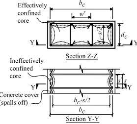
In a circular section, the concrete is confined uniformly. This is not the case for rectangular or square sections. The confined region is highly affected by configuration of reinforcement as illustrated by Sheikh and Yeh (1986). Closer spacing of both longitudinal and lateral reinforcement results in a higher proportion of the effectively confined area as shown in Figure 2-1.
Figure 2-1 Effectively confined concrete area (adopted from Sheikh and Yeh, 1986) Tie Level
13
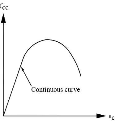
The confinement can be provided through such mechanisms as conventional internal reinforcement, external reinforcement, external jackets (made of concrete, steel, or fiber reinforced polymer, etc.), or external prestressing (Liu et al., 2008). There are some general agreements on the differences of stress-strain relationship of confined concrete compared to that of plain concrete. These main differences are: (1) increment of the compressive strength; (2) flatter post peak descending branch of the curve; and (3) increment of ultimate compressive strain. These improved stress-strain relationships results in more ductile behavior which leads to higher energy absorbing capacity. It is clear that confinement elements and their resulting confining stress distribution play important part in the improved behavior. Reviews of some confinement studies from the literature are presented in the following sections.
2.3 STRESS-STRAIN RELATIONSHIP MODEL OF CONFINED
CONCRETE
In an unconfined concrete under pressure uniaxial stress state is experienced. The axial strain causes tensile strain in the transverse direction (Poisson’s effect) which can lead to vertical crack. In a confined concrete, this transvere strain is restrained by lateral pressure from confining reinforcement. This causes the concrete to enter a triaxial stress state which enhances the strength (Saatcioglu et al., 1992). The more confined core area, the stronger the confined concrete will be. Thus, it is important to know how this confinement affects the stress-strain behavior of the concrete. In this section, some stress-strain relationship models of confined concrete are discussed. Some models are elaborated more due to their relevance to this study, while other models are briefly discussed to give general idea of what have been done by others on this research area.
2.3.1 Sheikh and Uzumeri (1980, 1982)
14
al. (1955) suggested trilinear stress-strain curve for unconfined and confined concrete as shown in Figure 2-2. The variable used to define the curve was only volumetric ratio of tie steel to concrete core.
Figure 2-2 Stress-strain curve proposed by Chan (adopted from Chan et al., 1955)
Roy and Sozen (1965) suggested bilinear curve of stress strain relationship as shown in Figure 2-3. The variable used to define the curve were volumetric ratio of tie steel to concrete core, and ratio of section dimension to tie spacing.
Figure 2-3 Stress-strain curve proposed by Roy and Sozen (adopted from Roy and Sozen, 1965)
Soliman and Yu (1967) suggested stress strain curve as shown in Figure 2-4. The variable used to define the curve were area of tie steel bar, tie spacing, and section geometry.
O
A
B
C
Ec f p fcc
fc
Ec
2
c
fc
c
f c'
0.5fc'
15
Figure 2-4 Stress-strain curve proposed by Soliman and Yu (adopted from Soliman and Yu, 1967)
Sargin (1971) suggested stress strain curve as shown in Figure 2-5. The variable used to define the curve were volumetric ratio of lateral steel to concrete core, ratio of width of concrete core to tie spacing, steel strength, and strength of plain concrete.
Figure 2-5 Stress-strain curve proposed by Sargin (adopted from Sargin, 1971)
Kent and Park (1971) suggested stress strain curve as shown in Figure 2-6. The variable used to define the curve were volumetric ratio of lateral steel to concrete core, ratio of width of concrete core to tie spacing, and strength of plain concrete.
fc
c fcc
f .8fcc
ce s Parabola
fcc
c
16
Figure 2-6 Stress-strain curve proposed by Kent and Park (adopted from Kent and Park, 1971)
Vallenas et al. (1977) suggested stress strain curve as shown in Figure 2-7. The variable used to define the curve were volumetric ratio of lateral steel to concrete core, ratio of area of longitudinal steel to area of cross section, sizes of tie bar and longitudinal bar, ratio of core dimension to tie spacing, steel strength, and strength of plain concrete.
Figure 2-7 Stress-strain curve proposed by Vallenas et al. (adopted from Vallenas et al., 1977)
Sheikh and Uzumeri (1980) themselves suggested stress strain curve as shown in Figure 2-8. The variable used to define the curve were volumetric ratio of lateral steel to concrete core, distribution of longitudinal steel around the core