SEKOLAH TINGGI TEKNOLOGI NASIONAL, 14 Desember 2013 E 81
DAMPER WINDING PHENOMENA OF SYNCHRONOUS GENERATOR
UNDER UNBALANCED STEADY-STATE CONDITION:
A CASE OF 500 KV EHV JAMALI SYSTEM
Sugiarto 1), Sasongko Pramono Hadi 2), Tumiran 2), F. Danang Wijaya2)
1) Electrical Engineering Department, Sekolah Tinggi Teknologi Nasional, Yogyakarta, Indonesia.
2) Electrical Engineering Department, Gadjah Mada University, Yogyakarta, Indonesia.
[email protected] , [email protected], [email protected]
ABSTRACT
The performance of three different damper winding configurations of a synchronous generator under unbalanced steady-state condition of the power system to which it is connected are investigated in this paper. This synchronous generator is a source of electrical energy generation system in the 500 kV EHV Jawa-Madura-Bali (or Jamali) System with untransposed transmission lines and many single-phase loads.
Induced currents of damper windings under the unbalanced steady-state system conditions, when the synchronous generator is equipped with and without damper winding, are measured and analyzed. Active windows with this model are developed using Matlab’s Graphical User Interface (GUI) capability to examine the dynamic behavior of the machine after small perturbations, focusing on electromagnetically dynamic as affected by load unbalance. EDSA 2000 software is used to derive the generator’s terminal inputs through load-flow analysis on the grid.
Keywords: Damper winding, Unbalanced steady-state condition, The 500 kV EHV Jamali, GUI, EDSA 2000
INTRODUCTION
Many researcher have studied the performance of damper windings since their introduction to synchronous generator (Doherty and Nicle, 1926;
Boldea, 2006). However, the characteristics of
damper windings and their effects on the dynamics of generator in the electric power system have yet
to be sufficiently clarified (Matsuki et al, 1994).
Moreover, study considering the experimental
aspect of damper windings effect have been quite rare. The direct measurement of damper winding currents is quite difficult since the damper windings rotate with the rotor. Then, it has been generally difficult to realize the state of including damper in the practical generator to check the effects of the damper windings experimentally. Therefore, only simulation studies have been conducted to investigate them by including the generator parameters related to the damper windings in the analysis. But the simulation has a consequent it follows that the accuracy of results obtained by analytical techniques has been difficult to be checked, leaving a lot of uncertainties about the characteristics of damper windings.
A 820 MVA round-rotor synchronous generator model has been specially designed for
investigating the characteristics of damper
windings. A new method of measuring both induced currents and voltages in the damper bars has been developed. The damper bars are specially
designed to be easily interconnected or
disconnected to simulate the state of including or that of excluding damper effect. The performances
of the damper windings under the power system
oscillations are investigated analytically in this paper. The differences in performance between the machine with and without damper windings are discussed in terms of its induced currents of damper windings and generator terminal values such as electrical power output. The simulation was conducted on a one-generator connected to the 500 kV EHV Jamali System.
STUDYSYSTEM
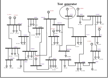
The studied power system is the 500 kV EHV Jamali System that comprises 4-regions, such as Banten-Jakarta (Region 1) , West Java (Region 2), Central Yogyakarta (Region 3) and East Java-Bali (Region 4). It also has 71 line nodes, 27 lines of inter buses and 9 generator nodes, as shown in
Fig. 1. In this system, Paiton’s bus is the swing
node and others are the PV nodes. System capacity is 100,000 MVA. The Test generators are Tanjung Jati B.
Test generator
SEKOLAH TINGGI TEKNOLOGI NASIONAL, 14 Desember 2013 E 82 Fig. 1. The studied power system
The synchronous generator used in this study is
a 820 MVA. 4-pole, 50Hz, round-rotor generator,
which is connected to the 500 kV EHV Jamali System through a 18 kV parallel transmission line.
Fig. 2. Balanced generator with unbalanced inputs
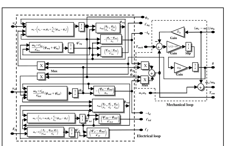
Fig. 3. The inside section of synchronous generator
The model of this generator is shown in Fig. 3. The generator has single damper per each axis
winding, such d-axis and q-axis. Damper windings
in the equivalent generator model can be used to
represent physical armotisseur windings (Fig. 4).
Fig. 4. Generator winding with armotiseur a-axis
Mechanical loop
Electrical loop
SEKOLAH TINGGI TEKNOLOGI NASIONAL, 14 Desember 2013 E 83 The mathematical description or model
develop is based on concept of an ideal synchronous generator. The fields produced by the winding currents are assumed to be sinusoidal distributed around the air-gap. This assumption of sinusoidal field distribution ignores the space harmonics, which may have secondary effects on the machine’s behavior. It is also assumed that stator slots cause no appreciable variation of any of the rotor winding inductances with rotor angle.
To investigate the effect of damper windings on generators under unbalanced steady state
operation, a “hybrid” method by combination
between unbalanced three phase load flow analysis
and rotor’s qd0 reference frame of synchronous
generator model which substitutes the model of generator in load flow analysis can be used.
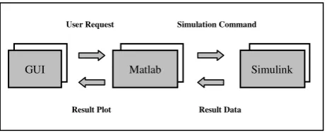
A software package which applied Matlab’s GUI facilities has been created for analysis damper winding phenomena of synchronous generator under unbalanced steady-state conditions (Fig. 5). As an example of using Matlab’s GUI capabilities, menu and plotting commands are implemented in a script file to provide interactive windows. The main menu, which is displayed after running the file, are shown in Fig. 6 and Fig. 7.
The verification of the generator model is judged through comparing between generator’s respon by PSS Tecquipment NE9070 (Fig. 10) and by the proposed simulator under no load, balanced and unbalanced conditions, respectively.
Fig. 5. Designed Simulator with GUI
Fig. 6. The main window of the software tool
Fig. 7. The window of inserting the inputs for balanced generator and unbalanced inputs
The verification of the generator model is judged through comparing between generator’s respon by PSS Tecquipment NE9070 (Fig. 8) and by the proposed simulator under no load, balanced and unbalanced conditions, respectively (Sugiarto
et al, 2013).
GUI Matlab Simulink
User Request Simulation Command
SEKOLAH TINGGI TEKNOLOGI NASIONAL, 14 Desember 2013 E 84 Fig. 8 . PSS Tecquipment NE9070
DEMONSTRATION
Using EDSA 2000 software program one can get the flow calculation results from Fig. 1. Table 1 presents inter-phase voltage values of the test generator terminal, before and after loading condition. It is shown that under unbalanced loads condition, the phase angles of terminal generator voltage are deviated from its balanced value. The biggest deviation occurs when the grid operates under balanced load condition.
Table 1. Values of generator terminal voltage
Conditions of
Synchronous Generator Phase
Tanjung Jati B
Voltage [p.u]
Connected the grid and load balance
a
b
c
Connected the grid and load imbalance of 5%
a
b
c
Fig. 14. Currents in phase-a of
Tanjung-Jati-B
of balanced loads and no-damper winding
( a )
( b )
Fig. 15. Currents of Tanjung-Jati-B at balanced loads
and d-axis damper winding:
a.in phase-a b. in d-axis damper
Current in Phase a
0 1 2 3 4 5 6 7 8 9 10
Current in Phase a
0 1 2 3 4 5 6 7 8 9 10
Current in horizontal-axis damper winding
0 1 2 3 4 5 6 7 8 9 10
SEKOLAH TINGGI TEKNOLOGI NASIONAL, 14 Desember 2013 E 85 ( b )
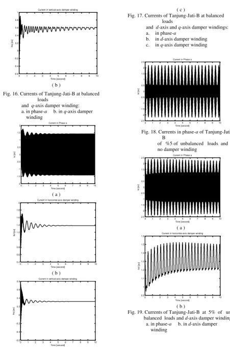
Fig. 16. Currents of Tanjung-Jati-B at balanced loads
Fig. 17. Currents of Tanjung-Jati-B at balanced loads
and d-axis and q-axis damper windings:
a. in phase-a
b. in d-axis damper winding
c. in q-axis damper winding
Fig. 18. Currents in phase-a of
Tanjung-Jati-B
of %5 of unbalanced loads and no damper winding
( a )
( b )
Fig. 19. Currents of Tanjung-Jati-B at 5% of
un-balanced loads and d-axis damper winding:
a.in phase-a b. in d-axis damper
Current in vertical-axis damper winding
0 1 2 3 4 5 6 7 8 9 10
Current in Phase a
0 1 2 3 4 5 6 7 8 9 10
Current in horizontal-axis damper winding
0 1 2 3 4 5 6 7 8 9 10
Current in vertical-axis damper winding
0 1 2 3 4 5 6 7 8 9 10
Current in Phase a
0 1 2 3 4 5 6 7 8 9 10
Current in Phase a
0 1 2 3 4 5 6 7 8 9 10
SEKOLAH TINGGI TEKNOLOGI NASIONAL, 14 Desember 2013 E 86 ( a )
( b )
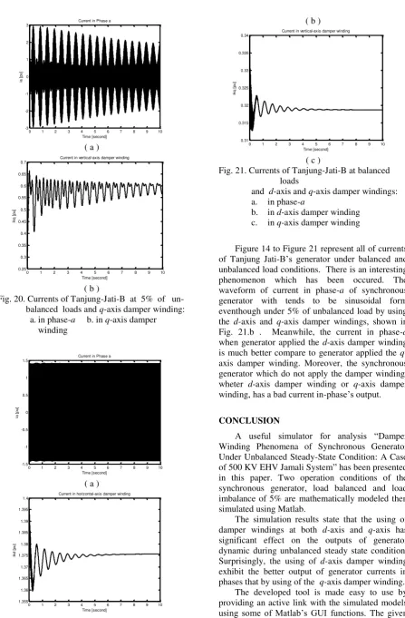
Fig. 20. Currents of Tanjung-Jati-B at 5% of
un-balanced loads and q-axis damper winding:
a.in phase-a b. in q-axis damper
winding
( a )
( b )
( c )
Fig. 21. Currents of Tanjung-Jati-B at balanced loads
and d-axis and q-axis damper windings:
a. in phase-a
b. in d-axis damper winding
c. in q-axis damper winding
Figure 14 to Figure 21 represent all of currents
of Tanjung Jati-B’s generator under balanced and
unbalanced load conditions. There is an interesting phenomenon which has been occured. The
waveform of current in phase-a of synchronous
generator with tends to be sinusoidal form eventhough under 5% of unbalanced load by using
the d-axis and q-axis damper windings, shown in
Fig. 21.b . Meanwhile, the current in phase-a
when generator applied the d-axis damper winding
is much better compare to generator applied the q
-axis damper winding. Moreover, the synchronous generator which do not apply the damper winding,
wheter d-axis damper winding or q-axis damper
winding, has a bad current in-phase’s output.
CONCLUSION
A useful simulator for analysis “Damper Winding Phenomena of Synchronous Generator Under Unbalanced Steady-State Condition: A Case
of 500 KV EHV Jamali System” has been presented
in this paper. Two operation conditions of the synchronous generator, load balanced and load imbalance of 5% are mathematically modeled then simulated using Matlab.
The simulation results state that the using of
damper windings at both d-axis and q-axis has
significant effect on the outputs of generator dynamic during unbalanced steady state condition.
Surprisingly, the using of d-axis damper winding
exhibit the better output of generator currents in
phases that by using of the q-axis damper winding.
The developed tool is made easy to use by providing an active link with the simulated models
using some of Matlab’s GUI functions. The given
Current in Phase a
0 1 2 3 4 5 6 7 8 9 10
Current in vertical-axis damper winding
0 1 2 3 4 5 6 7 8 9 10
Current in Phase a
0 1 2 3 4 5 6 7 8 9 10
Current in horizontal-axis damper winding
0 1 2 3 4 5 6 7 8 9 10
SEKOLAH TINGGI TEKNOLOGI NASIONAL, 14 Desember 2013 E 87 examples demonstrate helpfulness of the developed
tool for analyzing damper winding phenomenon of synchronous generator connected to the grid and under unbalanced steady-state operation
REFERENCES
Boldea, I., 2006, Synchronous Generator, Boca
Raton,FL: Taylor & Francis Group, LLC, 2006
Doherty, R.E. , Nickle, C.A., 1926, Synchronous Machines I - An Extension of Blondel's
Two-Reaction Theory, Transactions A.I.E.E., vol.
45, pp. 912-926, June.
Matsuki, J., Katagi, T, Okada, T., 1994,Damper
Windings Phenomena of Synchronous
Machines During System Oscillations, IEEE
Transaction on Energy Conversion, Vol. 9, No. 2, June.
Sugiarto, Hadi, S. P, Tumiran, Wijaya, F. D., 2013, Teaching the Large Synchronous Generator Dynamic Model under Unbalanced
Steady-State Operation, Poceedings of 2013
International Conference on Information Technology and Electrical Engineering, (ICITEE 2013), 7-8 October, Yogyakarta,