Programmable Controllers
Theory and Implementation
Second Edition
T
HEORY
AND
I
MPLEMENTATION
C O N T R O L L E R S
An Industrial Text Company Publication
Sec ond Ed ition
First edition 1988. Second edition 1997
Printed and bound in the United States of America 03 02 01 00 99 98 97 10 9 8 7 6 5 4 3 2 | | | | | | | | | | | |
| | | | | | | | | | | | | | | | | | | | | | | | | | | | | | | | | | | | | | | | | | | | |
Reproduction or translation of any part of this work beyond that permitted by Sections 107 and 108 of the 1976 United States Copyright act are unlawful.
Requests for permission, accompanying workbooks, or further information should be addressed to:
Industrial Text and Video Company 1950 Spectrum Circle
Tower A-First Floor Marietta, Georgia 30067 (770) 240-2200
(800) PLC-TEXT
Library of Congress Cataloging-in-Publication Data Bryan, L.A.
Programmable controllers: theory and implementation/L.A. Bryan, E.A. Bryan.—2nd ed.
p. cm. Includes index. ISBN 0-944107-32-X
1. Programmable controllers. I. Bryan, E.A. II. Title. TJ223.P76B795 1997
629.8'9—dc21 96-49350 CIP
Due to the nature of this publication and because of the different applications of programmable controllers, the readers or users and those responsible for applying the information herein contained must satisfy themselves to the acceptability of each application and the use of equipment therein mentioned. In no event shall the publisher and others involved in this publication be liable for direct, indirect, or consequential damages resulting from the use of any technique or equipment herein mentioned. The illustrations, charts, and examples in this book are intended solely to illustrate the methods used in each application example. The publisher and others involved in this publication cannot assume responsibility or liability for actual use based on the illustrative uses and applications.
C
ON T EN T S
Preface ... ix
About the Authors ... x
How to Use this Book ... xi
S
ECTION1 I
NTRODUCTORYC
ONCEPTS Chapter 1 Introduction to Programmable Controllers 1-1 Definition ... 41-2 A Historical Background ... 5
1-3 Principles of Operation... 10
1-4 PLCs Versus Other Types of Controls ... 13
1-5 PLC Product Application Ranges ... 22
1-6 Ladder Diagrams and the PLC ... 24
1-7 Advantages of PLCs ... 26
Chapter 2 Number Systems and Codes 2-1 Number Systems ... 34
2-2 Number Conversions ... 41
2-3 One’s and Two’s Complement ... 43
2-4 Binary Codes ... 46
2-5 Register Word Formats ... 50
Chapter 3 Logic Concepts 3-1 The Binary Concept ... 56
3-2 Logic Functions ... 57
3-3 Principles of Boolean Algebra and Logic ... 64
3-4 PLC Circuits and Logic Contact Symbology ... 68
S
ECTION2 C
OMPONENTS ANDS
YSTEMS Chapter 4 Processors, the Power Supply, and Programming Devices 4-1 Introduction ... 824-2 Processors ... 84
4-3 Processor Scan... 86
4-4 Error Checking and Diagnostics ... 92
4-5 The System Power Supply ... 98
4-6 Programming Devices ... 104
Chapter 5 The Memory System and I/O Interaction 5-1 Memory Overview ... 110
5-2 Memory Types ... 111
5-3 Memory Structure and Capacity ... 115
5-6 Summary of Memory, Scanning, and I/O Interaction ... 132
5-7 Memory Considerations ... 133
Chapter 6 The Discrete Input/Output System 6-1 Introduction to Discrete I/O Systems ... 138
6-2 I/O Rack Enclosures and Table Mapping ... 139
6-3 Remote I/O Systems ... 146
6-4 PLC Instructions for Discrete Inputs ... 147
6-5 Types of Discrete Inputs ... 150
6-6 PLC Instructions for Discrete Outputs ... 162
6-7 Discrete Outputs ... 165
6-8 Discrete Bypass/Control Stations ... 177
6-9 Interpreting I/O Specifications ... 178
6-10 Summary of Discrete I/O ... 182
Chapter 7 The Analog Input/Output System 7-1 Overview of Analog Input Signals ... 186
7-2 Instructions for Analog Input Modules ... 187
7-3 Analog Input Data Representation ... 189
7-4 Analog Input Data Handling ... 196
7-5 Analog Input Connections ... 199
7-6 Overview of Analog Output Signals ... 201
7-7 Instructions for Analog Output Modules ... 201
7-8 Analog Output Data Representation ... 203
7-9 Analog Output Data Handling... 207
7-10 Analog Output Connections ... 213
7-11 Analog Output Bypass/Control Stations ... 214
Chapter 8 Special Function I/O and Serial Communication Interfacing 8-1 Introduction to Special I/O Modules ... 218
8-2 Special Discrete Interfaces ... 220
8-3 Special Analog, Temperature, and PID Interfaces ... 224
8-4 Positioning Interfaces ... 233
8-5 ASCII, Computer, and Network Interfaces ... 248
8-6 Fuzzy Logic Interfaces ... 255
8-7 Peripheral Interfacing ... 260
S
ECTION3 PLC P
ROGRAMMING Chapter 9 Programming Languages 9-1 Introduction to Programming Languages ... 2769-2 Types of PLC Languages ... 276
9-3 Ladder Diagram Format ... 282
9-4 Ladder Relay Instructions ... 289
9-5 Ladder Relay Programming ... 298
9-6 Timers and Counters ... 306
9-8 Counter Instructions ... 312
9-9 Program/Flow Control Instructions ... 317
9-10 Arithmetic Instructions ... 322
9-11 Data Manipulation Instructions ... 334
9-12 Data Transfer Instructions ... 348
9-13 Special Function Instructions ... 358
9-14 Network Communication Instructions ... 363
9-15 Boolean Mnemonics ... 369
Chapter 10 The IEC 1131 Standard and Programming Language 10-1 Introduction to the IEC 1131 ... 374
10-2 IEC 1131-3 Programming Languages ... 380
10-3 Sequential Function Chart Programming ... 403
10-4 Types of Step Actions ... 419
10-5 IEC 1131-3 Software Systems ... 429
10-6 Summary ... 439
Chapter 11 System Programming and Implementation 11-1 Control Task Definition ... 444
11-2 Control Strategy ... 444
11-3 Implementation Guidelines ... 445
11-4 Programming Organization and Implementation ... 446
11-5 Discrete I/O Control Programming ... 465
11-6 Analog I/O Control Programming... 492
11-7 Short Programming Examples ... 521
Chapter 12 PLC System Documentation 12-1 Introduction to Documentation ... 536
12-2 Steps for Documentation ... 537
12-3 PLC Documentation Systems... 547
12-4 Conclusion ... 549
S
ECTION4 PLC P
ROCESSA
PPLICATIONS Chapter 13 Data Measurements and Transducers 13-1 Basic Measurement Concepts ... 55413-2 Interpreting Errors in Measurements... 560
13-3 Transducer Measurements... 565
13-4 Thermal Transducers ... 572
13-5 Displacement Transducers ... 586
13-6 Pressure Transducers ... 588
13-7 Flow Transducers ... 591
13-8 Vibration Transducers ... 599
13-9 Summary ... 608
Chapter 14 Process Responses and Transfer Functions 14-1 Process Control Basics ... 610
14-4 Laplace Transform Basics ... 632
14-5 Dead Time Responses in Laplace Form ... 644
14-6 Lag Responses in Laplace Form ... 645
14-7 Types of Second-Order Responses ... 653
14-8 Summary ... 665
Chapter 15 Process Controllers and Loop Tuning 15-1 Introduction ... 670
15-2 Controller Actions ... 671
15-3 Discrete-Mode Controllers ... 676
15-4 Continuous-Mode Controllers ... 690
15-5 Proportional Controllers (P Mode) ... 692
15-6 Integral Controllers (I Mode) ... 706
15-7 Proportional-Integral Controllers (PI Mode)... 715
15-8 Derivative Controllers (D Mode) ... 725
15-9 Proportional-Derivative Controllers (PD Mode)... 729
15-10 Proportional-Integral-Derivative Controllers (PID Mode) ... 736
15-11 Advanced Control Systems ... 744
15-12 Controller Loop Tuning ... 747
15-13 Summary ... 766
S
ECTION5 A
DVANCEDPLC T
OPICSANDN
ETWORKS Chapter 16 Artificial Intelligence and PLC Systems 16-1 Introduction to AI Systems ... 77416-2 Types of AI Systems ... 774
16-3 Organizational Structure of an AI System ... 776
16-4 Knowledge Representation ... 778
16-5 Knowledge Inference ... 781
16-6 AI Fault Diagnostics Application ... 788
Chapter 17 Fuzzy Logic 17-1 Introduction to Fuzzy Logic ... 798
17-2 History of Fuzzy Logic ... 801
17-3 Fuzzy Logic Operation ... 802
17-4 Fuzzy Logic Control Components ... 805
17-5 Fuzzy Logic Control Example ... 828
17-6 Fuzzy Logic Design Guidelines ... 835
Chapter 18 Local Area Networks 18-1 History of Local Area Networks ... 848
18-2 Principles of Local Area Networks ... 848
18-3 Network Topologies ... 851
18-4 Network Access Methods... 857
18-5 Communication Media ... 860
18-7 Network Protocols ... 866
18-8 Network Testing and Troubleshooting ... 874
18-9 Network Comparison and Selection Criteria ... 875
Chapter 19 I/O Bus Networks 19-1 Introduction to I/O Bus Networks ... 880
19-2 Types of I/O Bus Networks ... 883
19-3 Advantages of I/O Bus Networks... 885
19-4 Device Bus Networks ... 886
19-5 Process Bus Networks ... 899
19-6 I/O Bus Installation and Wiring Connections ... 910
19-7 Summary of I/O Bus Networks ... 916
S
ECTION6 I
NSTALLATIONANDS
TART-U
P Chapter 20 PLC Start-Up and Maintenance 20-1 PLC System Layout ... 92220-2 Power Requirements and Safety Circuitry ... 931
20-3 Noise, Heat, and Voltage Considerations... 935
20-4 I/O Installation, Wiring, and Precautions ... 942
20-5 PLC Start-Up and Checking Procedures ... 948
20-6 PLC System Maintenance ... 952
20-7 Troubleshooting the PLC System ... 954
Chapter 21 System Selection Guidelines 21-1 Introduction to PLC System Selection ... 962
21-2 PLC Sizes and Scopes of Applications ... 962
21-3 Process Control System Definition ... 969
21-4 Other Considerations ... 981
21-5 Summary ... 982
A
PPENDICES Appendix A Logic Symbols, Truth Tables, and Equivalent Ladder/Logic Diagrams ... 987Appendix B ASCII Reference ... 989
Appendix C Electrical Relay Diagram Symbols ... 991
Appendix D P&ID Symbols ... 993
Appendix E Equation of a Line and Number Tables ... 995
Appendix F Abbreviations and Acronyms ... 997
Appendix G Voltage-Current Laplace Transfer Function Relationships ... 999
Glossary ... 1001
P
REFACE
Since the first edition of this book in 1988, the capabilities of programmable logic controllers have grown by leaps and bounds. Likewise, the applications of PLCs have grown with them. In fact, in today’s increasingly computer-controlled environment, it is almost impossible to find a technical industry that does not use programmable controllers in one form or another. To respond to these phenomenal changes, we introduce the second edition of
Programmable Controllers: Theory and Implementation.
This second edition, like the first, provides a comprehensive theoretical, yet practical, look at all aspects of PLCs and their associated devices and systems. However, this version goes one step further with new chapters on advanced PLC topics, such as I/O bus networks, fuzzy logic, the IEC 1131-3 program-ming standard, process control, and PID algorithms. This new edition also presents revised, up-to-date information about existing topics, with expanded graphics and new, hands-on examples. Furthermore, the new layout of the book—with features like two-tone graphics, key terms lists, well-defined headings and sections, callout icons, and a revised, expanded glossary— makes the information presented even easier to understand.
This new edition has been a labor-intensive learning experience for all those involved. As with any task so large, we could never have done it alone. Therefore, we would like to thank the following companies for their help in bringing this book to press: Allen-Bradley Company—Industrial Computer Group, ASI-USA, B & R Industrial Automation, Bailey Controls Company, DeviceNet Vendors Association, ExperTune Software, Fieldbus Foundation, Hoffman Engineering Company, Honeywell—MicroSwitch Division, LANcity—Cable Modem Division of Bay Networks, Mitsubishi Electronics, Omron Electronics, Phoenix Contact, PLC Direct, PMC/BETA LP, Profibus Trade Organization, Schaevitz Engineering Company, Siemens Automation, Square D Company, Thermometrics, and WAGO.
We hope that you will find this book to be a valuable learning and reference tool. We have tried to present a variety of programmable control operations; however, with the unlimited variations in control systems, we certainly have not been able to provide an exhaustive list of PLC applications. Only you, armed with the knowledge gained through this book, can explore the true limits of programmable logic controllers.
A
B OU T
T H E
A
U T H OR S
LU I S BRYA N
Luis Bryan holds a Bachelor of Science in Electrical Engineering degree and a Master of Science in Electrical Engineering degree, both from the Univer-sity of Tennessee. His major areas of expertise are digital systems, electron-ics, and computer engineering. During his graduate studies, Luis was in-volved in several projects with national and international governmental agencies.
Luis has extensive experience in the field of programmable controllers. He was involved in international marketing activities, as well as PLC applica-tions development, for a major programmable controller manufacturer. He also worked for a consulting firm, providing market studies and company-specific consultations about PLCs. Furthermore, Luis has given lectures and seminars in Canada, Mexico, and South America about the uses of program-mable controllers. He continues to teach seminars to industry and government entities, including the National Aeronautics and Space Administration (NASA).
Luis is an active member of several professional organizations, including the Institute of Electrical and Electronics Engineers (IEEE) and the IEEE’s instrument and computer societies. He is a senior member of the Instrument Society of America, as well as a member of Phi Kappa Phi honor society and Eta Kappa Nu electrical engineering honor society. Luis has coauthored several other books about programmable controllers.
ER I C BRY A N
Eric Bryan graduated from the University of Tennessee with a Bachelor of Science in Electrical Engineering degree, concentrating in digital design and computer architecture. He received a Master of Science in Engineering degree from the Georgia Institute of Technology, where he participated in a special computer-integrated manufacturing (CIM) program. Eric’s special-ties are industrial automation methods, flexible manufacturing systems (FMS), and artificial intelligence. He is an advocate of artificial intelligence implementation and its application in industrial automation.
H
OW
T O
U
SE
T H I S
B
OOK
Welcome to Programmable Controllers: Theory and Implementation.
Be-fore you begin reading, please review the following strategies for using this book. By following these study strategies, you will more thoroughly under-stand the information presented in the text and, thus, be better able to apply this knowledge in real-life situations.
BE F O R E YO U BE G I N RE A D I N G
• Look through the book to familiarize yourself with its structure. • Read the table of contents to review the subjects you will be studying. • Familiarize yourself with the icons used throughout the text:
Chapter Highlights
Key Terms
• Look at the appendices to see what reference materials have been provided.
AS YO U ST U D Y EA C H CH A P T E R
• Before you start a chapter, read the Chapter Highlights paragraph at the beginning of the chapter’s text. This paragraph will give you an overview of what you’ll learn, as well as explain how the information presented in the chapter fits into what you’ve already learned and what you will learn. • Read the chapter, paying special attention to the bolded items. These are key terms that indicate important topics that you should understand after finishing the chapter.
• When you encounter an exercise, try to solve the problem yourself before looking at the solution. This way, you'll determine which topics you understand and which topics you should study further.
WH E N YO U FI N I S H EA C H CH A P T E R
• At the end of each chapter, look over the list of key terms to ensure that you understand all of the important subjects presented in the chapter. If you’re not sure about a term, review it in the text.
• Review the exercises to ensure that you understand the logic and equa-tions involved in each problem. Also, review the workbook and study guide, making sure that you can work all of the problems correctly. • When you’re sure that you thoroughly understand the information that has
I
N T RODU CT ORY
C
ON CEPT S
•
Introd uc tion to Prog rammab le Controllers
•Numb er Systems and Cod es
•
Log ic Conc ep ts
I
N T RODU CT I ON
T O
P
ROGRAM M ABLE
C
ON T ROLLERS
I find the great thing in this world is not so much where we stand as in what direction we are moving.
—Oliver Wendell Holmes
Figure 1-1. PLC conceptual application diagram. CH A P T E R
HI G H L I G H T S
Programmable controllers have many definitions. However, PLCs can be thought of in simple terms as industrial computers with specially designed architecture in both their central units (the PLC itself) and their interfacing circuitry to field devices (input/output connections to the real world). Every aspect of industry—from power generation to automobile painting to food packaging—uses programmable controllers to expand and enhance production. In this book, you will learn about all aspects of these powerful and versatile tools. This chapter will introduce you to the basics of programmable controllers—from their operation to their vast range of applications. In it, we will give you an inside look at the design philosophy behind their creation, along with a brief history of their evolution. We will also compare program-mable controllers to other types of controls to highlight the benefits and drawbacks of each, as well as pinpoint situations where PLCs work best. When you finish this chapter, you will understand the fundamentals of programmable controllers and be ready to explore the number systems associated with them.
1 -1 D
E F I N I T I O NProgrammable logic controllers, also called programmable controllers or PLCs, are solid-state members of the computer family, using integrated
circuits instead of electromechanical devices to implement control functions. They are capable of storing instructions, such as sequencing, timing, counting, arithmetic, data manipulation, and communication, to control industrial machines and processes. Figure 1-1 illustrates a conceptual diagram of a PLC application.
Programmable Controller Field
Inputs
Field Outputs
Measure Control
The Hydramatic Division of the General Motors Corporation specified the design criteria for the first programmable controller in 1968. Their primary goal was to eliminate the high costs associated with inflexible, relay-controlled systems. The specifications required a solid-state system with computer flexibility able to (1) survive in an industrial environment, (2) be easily programmed and maintained by plant engineers and technicians, and (3) be reusable. Such a control system would reduce machine downtime and provide expandability for the future. Some of the initial specifications included the following:
• The new control system had to be price competitive with the use of relay systems.
• The system had to be capable of sustaining an industrial environment. • The input and output interfaces had to be easily replaceable.
• The controller had to be designed in modular form, so that subassem-blies could be removed easily for replacement or repair.
• The control system needed the capability to pass data collection to a central system.
• The system had to be reusable.
• The method used to program the controller had to be simple, so that it could be easily understood by plant personnel.
As you will see throughout this book, programmable logic controllers are mature industrial controllers with their design roots based on the principles of simplicity and practical application.
The product implementation to satisfy Hydramatic’s specifications was underway in 1968; and by 1969, the programmable controller had its first product offsprings. These early controllers met the original specifications and opened the door to the development of a new control technology.
The first PLCs offered relay functionality, thus replacing the original hardwired relay logic, which used electrically operated devices to
mechani-cally switch electrical circuits. They met the requirements of modularity, expandability, programmability, and ease of use in an industrial environment. These controllers were easily installed, used less space, and were reusable. The controller programming, although a little tedious, had a recognizable plant standard: the ladder diagram format.
1 -2 A H
I S T O R I C A LB
A C K G R O U N DIn a short period, programmable controller use started to spread to other industries. By 1971, PLCs were being used to provide relay replacement as the first steps toward control automation in other industries, such as food and beverage, metals, manufacturing, and pulp and paper.
TH E CO N C E P T U A L DE S I G N O F T H E P L C
The first programmable controllers were more or less just relay replacers. Their primary function was to perform the sequential operations that were previously implemented with relays. These operations included ON/OFF control of machines and processes that required repetitive operations, such as transfer lines and grinding and boring machines. However, these programmable controllers were a vast improvement over relays. They were easily installed, used considerably less space and energy, had diagnostic indicators that aided troubleshooting, and unlike relays, were reusable if a project was scrapped.
Programmable controllers can be considered newcomers when they are compared to their elder predecessors in traditional control equipment technology, such as old hardwired relay systems, analog instrumentation, and other types of early solid-state logic. Although PLC functions, such as speed of operation, types of interfaces, and data-processing capabilities, have improved throughout the years, their specifications still hold to the designers’ original intentions—they are simple to use and maintain.
TO D AY’S PR O G R A M M A B L E CO N T R O L L E R S
Many technological advances in the programmable controller industry continue today. These advances not only affect programmable controller design, but also the philosophical approach to control system architecture. Changes include both hardware (physical components) and software
(con-trol program) upgrades. The following list describes some recent PLC hardware enhancements:
• Faster scan times are being achieved using new, advanced micro-processor and electronic technology.
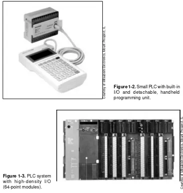
• Small, low-cost PLCs (see Figure 1-2), which can replace four to ten relays, now have more power than their predecessor, the simple relay replacer.
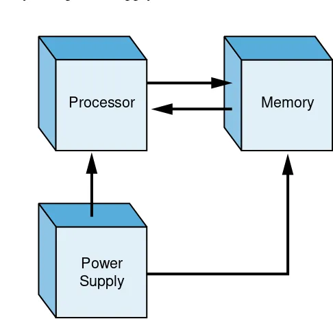
• High-density input/output (I/O) systems (see Figure 1-3) provide space-efficient interfaces at low cost.
(proportional-integral-derivative), network, CANbus, fieldbus, ASCII communica-tion, positioning, host computer, and language modules (e.g., BASIC, Pascal).
• Mechanical design improvements have included rugged input/output enclosures and input/output systems that have made the terminal an integral unit.
• Special interfaces have allowed certain devices to be connected directly to the controller. Typical interfaces include thermocouples, strain gauges, and fast-response inputs.
• Peripheral equipment has improved operator interface techniques, and system documentation is now a standard part of the system.
Figure 1-3. PLC system with hig h-d ensity I/O (64-point modules).
Figure 1-2. Small PLC with built-in I/O and detachable, handheld programming unit.
All of these hardware enhancements have led to the development of programmable controller families like the one shown in Figure 1-4. These families consist of a product line that ranges from very small “microcontrollers,” with as few as 10 I/O points, to very large and
C
o
u
rt
e
s
y
o
f
M
it
s
u
b
is
h
i
E
le
c
tr
o
n
ic
s
,
M
o
u
n
t
P
ro
s
p
e
c
t,
I
L
C
o
u
rt
e
s
y
o
f
M
it
s
u
b
is
h
i
E
le
c
tr
o
n
ic
s
,
M
o
u
n
t
P
ro
s
p
e
c
t,
I
sophisticated PLCs, with as many as 8,000 I/O points and 128,000 words of memory. These family members, using common I/O systems and programming peripherals, can interface to a local communication network. The family concept is an important cost-saving development for users.
Figure 1-4. Allen-Bradley’s programmable controller family concept with several PLCs.
Like hardware advances, software advances, such as the ones listed below, have led to more powerful PLCs:
• PLCs have incorporated object-oriented programming tools and multiple languages based on the IEC 1131-3 standard.
• Small PLCs have been provided with powerful instructions, which extend the area of application for these small controllers.
• High-level languages, such as BASIC and C, have been implemented in some controllers’ modules to provide greater programming flex-ibility when communicating with peripheral devices and manipulat-ing data.
• Advanced functional block instructions have been implemented for ladder diagram instruction sets to provide enhanced software capabil-ity using simple programming commands.
• Diagnostics and fault detection have been expanded from simple system diagnostics, which diagnose controller malfunctions, to include machine diagnostics, which diagnose failures or malfunctions of the controlled machine or process.
• Floating-point math has made it possible to perform complex calcu-lations in control applications that require gauging, balancing, and statistical computation.
C
o
u
rt
e
s
y
o
f
A
lle
n
-B
ra
d
le
y
,
H
ig
h
la
n
d
,
H
e
ig
h
ts
,
O
• Data handling and manipulation instructions have been improved and simplified to accommodate complex control and data acquisition applications that involve storage, tracking, and retrieval of large amounts of data.
Programmable controllers are now mature control systems offering many more capabilities than were ever anticipated. They are capable of communicating with other control systems, providing production reports, scheduling production, and diagnosing their own failures and those of the machine or process. These enhancements have made programmable controllers important contributors in meeting today’s demands for higher quality and productivity. Despite the fact that programmable controllers have become much more sophisticated, they still retain the simplicity and ease of operation that was intended in their original design.
PR O G R A M M A B L E CO N T R O L L E R S A N D T H E FU T U R E
The future of programmable controllers relies not only on the continuation of new product developments, but also on the integration of PLCs with other control and factory management equipment. PLCs are being incorporated, through networks, into computer-integrated manufacturing (CIM) systems, combining their power and resources with numerical controls, robots, CAD/ CAM systems, personal computers, management information systems, and hierarchical computer-based systems. There is no doubt that programmable controllers will play a substantial role in the factory of the future.
New advances in PLC technology include features such as better operator interfaces, graphic user interfaces (GUIs), and more human-oriented man/ machine interfaces (such as voice modules). They also include the development of interfaces that allow communication with equipment, hardware, and software that supports artificial intelligence, such as fuzzy logic I/O systems.
Software advances provide better connections between different types of equipment, using communication standards through widely used networks. New PLC instructions are developed out of the need to add intelligence to a controller. Knowledge-based and process learning–type instructions may be introduced to enhance the capabilities of a system.
Figure 1-5. Programmable controller block diagram.
Figure 1-6. Block diagram of major CPU components.
Processor
Power Supply
Memory
The central processing unit (CPU) governs all PLC activities. The following three components, shown in Figure 1-6, form the CPU:
• the processor • the memory system • the system power supply
O U T P U T S I
N P U T S
Central Processing
Unit
1 -3 P
R I N C I P L E S O FO
P E R AT I O NA programmable controller, as illustrated in Figure 1-5, consists of two basic sections:
Figure 1-7. Illustration of a scan.
The operation of a programmable controller is relatively simple. The input/ output (I/O) system is physically connected to the field devices that are
encountered in the machine or that are used in the control of a process. These field devices may be discrete or analog input/output devices, such as limit switches, pressure transducers, push buttons, motor starters, solenoids, etc. The I/O interfaces provide the connection between the CPU and the informa-tion providers (inputs) and controllable devices (outputs).
During its operation, the CPU completes three processes: (1) it reads, or
accepts, the input data from the field devices via the input interfaces, (2) it
executes, or performs,the control program stored in the memory system, and
(3) it writes, or updates, the output devices via the output interfaces. This
process of sequentially reading the inputs, executing the program in memory, and updating the outputs is known as scanning. Figure 1-7 illustrates a
graphic representation of a scan.
The input/output system forms the interface by which field devices are
connected to the controller (see Figure 1-8). The main purpose of the interface is to condition the various signals received from or sent to external field devices. Incoming signals from sensors (e.g., push buttons, limit switches, analog sensors, selector switches, and thumbwheel switches) are wired to terminals on the input interfaces. Devices that will be controlled, like motor starters, solenoid valves, pilot lights, and position valves, are connected to the terminals of the output interfaces. The system power supply provides
all the voltages required for the proper operation of the various central processing unit sections.
(1)
(2)
(3)
SCAN
READ
EXECUTE
Figure 1-9. (a) Personal computer used as a programming device and (b) a mini-programmer unit.
Chapters 4 and 5 will present a more detailed discussion of the central processing unit and how it interacts with memory and input/output interfaces. Chapters 6, 7, and 8 discuss the input/output system.
Although not generally considered a part of the controller, the programming device, usually a personal computer or a manufacturer’s miniprogrammer
unit, is required to enter the control program into memory (see Figure 1-9). The programming device must be connected to the controller when entering or monitoring the control program.
Figure 1-8. Input/output interface.
0 1 2 3 4 5 6 7 0 1 2 3 4 5 6 7 0 1 2 3 4 5 6 7 0 1 2 3 4 5 6 7 0 1 2 3 4 5 6 7 0 1 2 3 4 5 6 7
0 1 2 3
1 -4 P L C
SV
E R S U SO
T H E RT
Y P E S O FC
O N T R O L SP L CS VE R S U S RE L AY CO N T R O L
For years, the question many engineers, plant managers, and original equipment manufacturers (OEMs) asked was, “Should I be using a programmable controller?” At one time, much of a systems engineer’s time was spent trying to determine the cost-effectiveness of a PLC over relay control. Even today, many control system designers still think that they are faced with this decision. One thing, however, is certain—today’s demand for high quality and productivity can hardly be fulfilled economically without electronic control equipment. With rapid technology developments and increasing competition, the cost of programmable controls has been driven down to the point where a PLC-versus-relay cost study is no longer necessary or valid. Programmable controller applications can now be evaluated on their own merits.
When deciding whether to use a PLC-based system or a hardwired relay system, the designer must ask several questions. Some of these questions are:
• Is there a need for flexibility in control logic changes?
• Is there a need for high reliability?
• Are space requirements important?
• Are increased capability and output required?
• Are there data collection requirements?
• Will there be frequent control logic changes?
• Will there be a need for rapid modification?
• Must similar control logic be used on different machines?
• Is there a need for future growth?
• What are the overall costs?
If system requirements call for flexibility or future growth, a programmable controller brings returns that outweigh any initial cost advantage of a relay control system. Even in a case where no flexibility or future expansion is required, a large system can benefit tremendously from the troubleshooting and maintenance aids provided by a PLC. The extremely short cycle (scan) time of a PLC allows the productivity of machines that were previously under electromechanical control to increase considerably. Also, although relay control may cost less initially, this advantage is lost if production downtime due to failures is high.
P L CS VE R S U S CO M P U T E R CO N T R O L S
Figure 1-10. The uncluttered control panel of an installed PLC system.
The architecture of a PLC’s CPU is basically the same as that of a general purpose computer; however, some important characteristics set them apart. First, unlike computers, PLCs are specifically designed to survive the harsh conditions of the industrial environment. A well-designed PLC can be placed in an area with substantial amounts of electrical noise, electromagnetic interference, mechanical vibration, and noncondensing humidity.
C
o
u
rt
e
s
y
o
f
O
m
ro
n
E
le
c
tr
o
n
ic
s
,
S
c
h
a
u
m
b
u
rg
,
A second distinction of PLCs is that their hardware and software are designed for easy use by plant electricians and technicians. The hardware interfaces for connecting field devices are actually part of the PLC itself and are easily connected. The modular and self-diagnosing interface circuits are able to pinpoint malfunctions and, moreover, are easily removed and replaced. Also, the software programming uses conventional relay ladder symbols, or other easily learned languages, which are familiar to plant personnel.
Whereas computers are complex computing machines capable of executing several programs or tasks simultaneously and in any order, the standard PLC executes a single program in an orderly, sequential fashion from first to last instruction. Bear in mind, however, that PLCs as a system continue to become more intelligent. Complex PLC systems now provide multiprocessor and multitasking capabilities, where one PLC may control several programs in a single CPU enclosure with several processors (see Figure 1-11).
Figure 1-11. PLC system with multiprocessing and multitasking capabilities.
P L CS VE R S U S PE R S O N A L CO M P U T E R S
With the proliferation of the personal computer (PC), many engineers have found that the personal computer is not a direct competitor of the PLC in control applications. Rather, it is an ally in the implementation of the control solution. The personal computer and the PLC possess similar CPU architec-ture; however, they distinctively differ in the way they connect field devices.
While new, rugged, industrial personal computers can sometimes sustain midrange industrial environments, their interconnection to field devices still presents difficulties. These computers must communicate with I/O interfaces not necessarily designed for them, and their programming languages may not meet the standards of ladder diagram programming. This presents a problem to people familiar with the ladder diagram standard when troubleshooting and making changes to the system.
C
o
u
rt
e
s
y
o
f
G
id
d
in
g
s
&
L
e
w
is
,
F
o
n
d
d
u
L
a
c
,
W
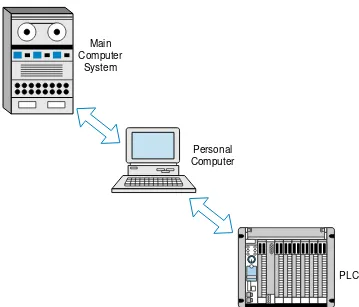
The personal computer is, however, being used as the programming device of choice for PLCs in the market, where PLC manufacturers and third-party PLC support developers come up with programming and documentation systems for their PLC product lines. Personal computers are also being employed to gather process data from PLCs and to display information about the process or machine (i.e., they are being used as graphic user interfaces, or GUIs). Because of their number-crunching capabilities, personal computers are also well suited to complement programmable controllers and to bridge the communication gap, through a network, between a PLC system and other mainframe computers (see Figure 1-12).
Figure 1-12. A personal computer used as a bridge between a PLC system and a main computer system.
Some control software manufacturers, however, utilize PCs as CPU hardware to implement a PLC-like environment. The language they use is based on the International Electrotechnical Commission (IEC) 1131-3 standard, which is a graphic representation language (sequential function charts) that includes ladder diagrams, functional blocks, instruction lists, and structured text. These software manufacturers generally do not provide I/O hardware interfaces; but with the use of internal PC communication cards, these systems can communicate with other PLC manufacturers’ I/O hardware modules. Chapter 10 explains the IEC 1131-3 standard.
PLC Personal
Computer Main
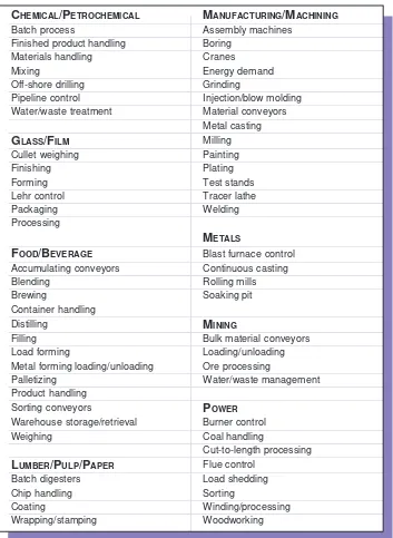
Since its inception, the PLC has been successfully applied in virtually every segment of industry, including steel mills, paper plants, food-process-ing plants, chemical plants, and power plants. PLCs perform a great variety of control tasks, from repetitive ON/OFF control of simple machines to sophisticated manufacturing and process control. Table 1-1 lists a few of the major industries that use programmable controllers, as well as some of their typical applications.
Table 1-1. Typical programmable controller applications.
TY P I C A L AR E A S O F P L C AP P L I C AT I O N S
CHEMICAL/PETROCHEMICAL MANUFACTURING/MACHINING
s s e c o r p h c t a
B Assemblymachines
g n il d n a h t c u d o r p d e h s i n i
F Boring
g n il d n a h s l a i r e t a
M Cranes
g n i x i
M Energydemand
g n il li r d e r o h s -f f
O Grinding
l o r t n o c e n il e p i
P Injection/blowmolding
t n e m t a e r t e t s a w / r e t a
W Materialconveyors
g n i t s a c l a t e M GLASS/FILM Mliilng
g n i h g i e w t e ll u
C Painting
g n i h s i n i
F Plating
g n i m r o
F Teststands
l o r t n o c r h e
L Tracerlathe
g n i g a k c a
P Welding
g n i s s e c o r P
METALS
FOOD/BEVERAGE Blastfurnacecontrol
s r o y e v n o c g n i t a l u m u c c
A Continuouscasting
g n i d n e l
B Rolilngmills
g n i w e r
B Soakingpit
g n il d n a h r e n i a t n o C g n il li t s i
D MINING
g n il li
F Bulkmaterialconveyors
g n i m r o f d a o
L Loading/unloading
g n i d a o l n u / g n i d a o l g n i m r o f l a t e
M Oreprocessing
g n i z i t e ll a
P Water/wastemanagement
g n il d n a h t c u d o r P s r o y e v n o c g n i t r o
S POWER
l a v e i r t e r / e g a r o t s e s u o h e r a
W Burnercontrol
g n i h g i e
W Coalhandilng
g n i s s e c o r p h t g n e l -o t -t u C
LUMBER/PULP/PAPER Fluecontrol
s r e t s e g i d h c t a
B Loadshedding
g n il d n a h p i h
C Sorting
g n i t a o
C Winding/processing
g n i p m a t s / g n i p p a r
Table 1-2. Examples of PLC applications.
Because the applications of programmable controllers are extensive, it is impossible to list them all in this book. However, Table 1-2 provides a small sample of how PLCs are being used in industry.
AUTOMOTIVE
. g n i r o t i n o M e n i g n E n o i t s u b m o C l a n r e t n
I A PLCacquiresdatarecordedfrom e d u l c n i n e k a t s t n e m e r u s a e M . e n i g n e n o i t s u b m o c l a n r e t n i e h t t a d e t a c o l s r o s n e s l i o , e r u t a r e p m e t t s u a h x e , e u q r o t , s M P R , e r u t a r e p m e t l i o , e r u t a r e p m e t r e t a w . g n i m i t d n a , e r u s s e r p d l o f i n a m , e r u s s e r p . g n i t s e T n o i t c u d o r P r o t e r u b r a
C PLCsprovideon-ilneanalysisofautomotive t s e t e h t e c u d e r y l t n a c i f i n g i s s m e t s y s e h T . e n il y l b m e s s a n o i t c u d o r p a n i s r o t e r u b r a c , m u u c a v , e r u s s e r P . s r o t e r u b r a c y t il a u q r e t t e b d n a d l e i y r e t a e r g g n i d i v o r p e li h w , e m i t . d e t s e t s e l b a i r a v e h t f o e m o s e r a w o l f r i a d n a l e u f d n a . s e n i h c a M n o i t c u d o r P e v i t o m o t u A g n i r o t i n o
M Thesystemmonitorstotalparts, . y c n e i c i f f e e n i h c a m d n a , e m i t e l c y c e n i h c a m , d e c u d o r p s t r a p , s t r a p d e t c e j e r . t f i h s h c a e r e t f a r o e m i t y n a r o t a r e p o e h t o t e l b a li a v a s i a t a d l a c i t s i t a t S . g n i t s e T d n a y l b m e s s A e v l a V g n i r e e t S r e w o
P ThePLCsystem controlsa
g n i n r u t t h g i r d n a t f e l e z i m i x a m o t d n a s e v l a v e h t f o e c n a l a b r e p o r p e r u s n e o t e n i h c a m . s o i t a r
CHEMICALANDPETROCHEMICAL
. g n i s s e c o r P e n e l y h t E d n a a i n o m m
A Programmablecontrollersmonitor and e h T . g n i r u t c a f u n a m e n e l y h t e d n a a i n o m m a g n i r u d d e s u s r o s s e r p m o c e g r a l l o r t n o c r o s s e r p m o c , s t e k c o p e c n a r a e l c f o n o i t a r e p o , s e r u t a r e p m e t g n i r a e b s r o t i n o m C L P d n a , e r u s s e r p , s e r u t a r e p m e t e g r a h c s i d , n o i t a r b i v , n o i t p m u s n o c r e w o p , d e e p s . w o l f n o i t c u s . s e y
D PLCsmonitorandcontrolthedyeprocessingusedinthetextlieindustry.They . s e u l a v d e n i m r e t e d e r p o t s r o l o c d n e l b d n a h c t a m . g n i h c t a B l a c i m e h
C ThePLCcontrolsthebatchingratiooftwoormorematerials h c a e f o e g r a h c s i d f o e t a r e h t s e n i m r e t e d m e t s y s e h T . s s e c o r p s u o u n i t n o c a n i d n a d e g g o l e b n a c s e p i c e r h c t a b l a r e v e S . s d r o c e r y r o t n e v n i s p e e k d n a l a i r e t a m . r o t a r e p o e h t m o r f d n a m m o c n o r o y ll a c i t a m o t u a d e v i e r t e r . l o r t n o C n a
F PLCscontrolfansbasedonlevelsoftoxic gases inachemical l e v e l t e s e r p a n e h w s e s a g s e v o m e r y l e v i t c e f f e m e t s y s s i h T . t n e m n o r i v n e n o i t c u d o r p d n a , g n il c y c , p o t s / t r a t s n a f e h t s l o r t n o c C L P e h T . d e h c a e r s i n o i t a n i m a t n o c f o . d e z i m i n i m s i n o i t p m u s n o c y g r e n e e li h w d e n i a t n i a m e r a s l e v e l y t e f a s t a h t o s , s d e e p s . n o i t u b i r t s i D d n a n o i s s i m s n a r T s a
G Programmablecontrollersmonitor and s i a t a D . s m e t s y s n o i t u b i r t s i d d n a n o i s s i m s n a r t s a g f o s w o l f d n a s e r u s s e r p e t a l u g e r . m e t s y s C L P e h t o t d e t t i m s n a r t d n a d l e i f e h t n i d e r u s a e m d n a d e r e h t a g . l o r t n o C n o i t a t S p m u P e n i l e p i
P PLCscontrol mainilneandbooster pumpsfor h g i h / w o l k n a t d n a , e g r a h c s i d , n o i t c u s , w o l f e r u s a e m y e h T . n o i t u b i r t s i d li o e d u r c a t a D d n a l o r t n o C y r o s i v r e p u S ( A D A C S h t i w n o i t a c i n u m m o c e l b i s s o P . s t i m i l . e n il e p i p e h t f o n o i s i v r e p u s l a t o t e d i v o r p n a c s m e t s y s ) n o i t s i u q c A . s d l e i F l i
Table 1-2 continued.
GLASSPROCESSING
. l o r t n o C r h e L g n i l a e n n
A PLCscontrolthelehrusedtoremovetheinternalstress g n il a e n n a e h t g n i w o ll o f y b n o it a r e p o e h t s l o r t n o c m e t s y s e h T . s t c u d o r p s s a l g m o r f g n il o o c d i p a r d n a , g n i n i a r t s , g n il a e n n a , g n i t a e h e r e h t g n i r u d e v r u c e r u t a r e p m e t n i e d a m e r a s t n e m e v o r p m I . s e n o z g n il o o c d n a g n it a e h t n e r e f fi d h g u o r h t s e s s e c o r p . n o it a z il it u y g r e n e d n a , t s o c r o b a l n i n o it c u d e r , p a r c s o t s s a l g d o o g f o o it a r e h t . g n i h c t a B s s a l
G PLCscontrolthebatchweighingsystemaccordingtostoredglass d n a o t d e e f n i r o f s r e d e e f c it e n g a m o r t c e l e e h t s l o r t n o c o s l a m e t s y s e h T . s a l u m r o f . t n e m p i u q e r e h t o d n a , s e t a g f f o -t u h s l a u n a m , s r e p p o h h g i e w e h t m o r f d e e f t u o . g n i h g i e W t e l l u
C PLCsdirecttheculletsystem bycontrolilngthevibratorycullet d n a n o i t a r e p o f o s e c n e u q e s ll A . r o y e v n o c e l t t u h s d n a , e l a c s t l e b -t h g i e w , r e d e e f . e s u e r u t u f r o f C L P e h t y b t p e k e r a d e h g i e w s e it it n a u q f o y r o t n e v n i . t r o p s n a r T h c t a
B PLCscontrolthebatchtransportsystem,includingreversiblebetl e l t t u h s , s r e p p o h g n i d l o h , e s u o h t e ll u c e h t o t s r o y e v n o c r e f s n a r t , s r o y e v n o c e g r a h c s i d e h t r e t f a n o it c a s e k a t r e ll o r t n o c e h T . s r o t a r a p e s c it e n g a m d n a , s r o y e v n o c s i t i e r e h w , e l t t u h s e c a n r u f e h t o t h c t a b d e x i m e h t s r e f s n a r t d n a r e x i m e h t m o r f . r e p p o h d e e f e c a n r u f e h t f o h t g n e l ll u f e h t o t d e g r a h c s i d
MANUFACTURING/MACHINING
. s e n i h c a M n o i t c u d o r
P ThePLC controlsandmonitorsautomaticproduction d n a n o i t c u d o r p t n u o c -e c e i p s r o t i n o m o s l a t I . s e t a r y c n e i c i f f e h g i h t a s e n i h c a m a s t c e t e d C L P e h t fi y l e t a i d e m m i n e k a t e b n a c n o it c a e v it c e r r o C . s u t a t s e n i h c a m . e r u li a f . s e n i h c a M e n i L r e f s n a r
T PLCsmonitor andcontrol alltransfer ilnemachining s e v i e c e r m e t s y s e h T . n o it a t s h c a e n e e w t e b g n i k c o l r e t n i e h t d n a s n o it a r e p o n o it a t s d e t n u o m -e n il e h t n o s n o i t i d n o c g n i t a r e p o e h t k c e h c o t r o t a r e p o e h t m o r f s t u p n i e n i h c a m r e t a e r g s e d i v o r p t n e m e g n a r r a s i h T . s n o it c n u fl a m y n a s t r o p e r d n a s l o r t n o c . s l e v e l p a r c s r e w o l d n a , s t c u d o r p y ti l a u q r e h g i h , y c n e i c if f e . e n i h c a M e r i
W Thecontroller monitorsthetimeandON/OFFcyclesofawire -f o n o i t a z i n o r h c n y s d n a l o r t n o c g n i p m a r s e d i v o r p m e t s y s e h T . e n i h c a m g n i w a r d e h t n i a t b o o t d n a m e d n o d e t r o p e r d n a d e d r o c e r e r a s e l c y c ll A . s e v i r d r o t o m c i r t c e l e . C L P e h t y b d e t a l u c l a c s a y c n e i c if f e s ' e n i h c a m . g n i g n a h C l o o
T ThePLCcontrolsasychronousmetalcutitngmachinewtihseveral d e s a b , d e c a l p e r e b d l u o h s l o o t h c a e n e h w f o k c a r t s p e e k m e t s y s e h T . s p u o r g l o o t s t n e m e c a l p e r d n a t n u o c e h t s y a l p s i d o s l a t I . s e r u t c a f u n a m ti s t r a p f o r e b m u n e h t n o . s p u o r g l o o t e h t ll a f o . g n i y a r p S t n i a
P PLCscontrolthepainitngsequencesinautomanufacturing.The t r a p e h t s k c a r t d n a n o it a m r o f n i r o l o c d n a e l y t s s r e t n e r e t u p m o c t s o h a r o r o t a r e p o e h t s e d o c e d r e ll o r t n o c e h T . h t o o b y a r p s e h t s e h c a e r ti li t n u r o y e v n o c e h t h g u o r h t n u g y a r p s e h T . t r a p e h t t n i a p o t s n u g y a r p s e h t s l o r t n o c n e h t d n a n o it a m r o f n i t r a p . t u p h g u o r h t t r a p e s a e r c n i d n a t n i a p e v r e s n o c o t d e z i m it p o s i t n e m e v o m
MATERIALSHANDLING
. e n i L g n i t a l P c i t a m o t u
Table 1-2 continued. . s m e t s y S l a v e i r t e R d n a e g a r o t
S APLCisusedtoloadpartsandcarrythemin e n a l a e k il n o i t a m r o f n i s k c a r t r e ll o r t n o c e h T . m e t s y s l a v e i r t e r d n a e g a r o t s e h t n i s e t o t r a l u c i t r a p a n i s t r a p f o y t i t n a u q e h t d n a , s e n a l c i f i c e p s o t d e n g i s s a s t r a p e h t , s r e b m u n r o d e d a o l s t r a p f o s u t a t s e h t n i s e g n a h c d i p a r s w o ll a t n e m e g n a r r a C L P s i h T . e n a l d n a s t u o t n i r p y r o t n e v n i s e d i v o r p o s l a r e ll o r t n o c e h T . m e t s y s e h t m o r f d e d a o l n u . s n o i t c n u f l a m y n a f o r o t a r e p o e h t s m r o f n i . s m e t s y S r o y e v n o
C Thesystemcontrolsallofthesequentialoperations,alarms, t I . r o y e v n o c e n il n i a m a n o s t r a p e t a l u c r i c d n a d a o l o t y r a s s e c e n c i g o l y t e f a s d n a e z i m i t p o o t g n i t r o s e n a l e l u d e h c s n a c d n a s e n a l t c e r r o c r i e h t o t s t c u d o r p s t r o s o s l a d e n i a t b o e b n a c s t c e j e r o t s t r a p d o o g f o o i t a r e h t g n il i a t e d s d r o c e R . y t u d r e z i t e ll a p . t f i h s h c a e f o d n e e h t t a . g n i s u o h e r a W d e t a m o t u
A ThePLCcontrolsandoptimizes themovement of , d e t a m o t u a n a n i s t s e u q e r s l a i r e t a m f o d n u o r a n r u t h g i h s e d i v o r p d n a s e n a r c g n i k c a t s e s a c d n a s r o y e v n o c e l s i a s l o r t n o c o s l a C L P e h T . e s u o h e r a w l a c i t r e v , e b u c -h g i h s e r u g i f l o r t n o c y r o t n e v n I . s t n e m e r i u q e r r e w o p n a m e c u d e r y l t n a c i f i n g i s o t s r e z i t e ll a p . t s e u q e r n o d e d i v o r p e b n a c d n a d e n i a t n i a m e r a
METALS
. g n i k a M l e e t
S ThePLCcontrolsandoperatesfurnacestoproducemetal in n e g y x o s e t a l u c l a c o s l a r e ll o r t n o c e h T . s n o i t a c i f i c e p s t e s e r p h t i w e c n a d r o c c a . s t n e m e r i u q e r r e w o p d n a , s n o i t i d d a y o ll a , s t n e m e r i u q e r . s y o l l A f o g n i d a o l n U d n a g n i d a o
L Throughaccurateweighingandloading d n a , e r o n o r i , l a o c f o y t i t n a u q e h t s r o t i n o m d n a s l o r t n o c m e t s y s e h t , s e c n e u q e s a o t l e e t s e h t f o e c n e u q e s g n i d a o l n u e h t l o r t n o c o s l a n a c t I . d e t l e m e b o t e n o t s e m il . r a c o d e p r o t . g n i t s a C s u o u n i t n o
C PLCsdirectthemoltensteeltransportladletothecontinuous -. n o i t a c i f i d il o s r o f d l o m d e l o o c -r e t a w a o t n i d e r u o p s i l e e t s e h t e r e h w , e n i h c a m g n i t s a c . g n i l l o R d l o
C PLCscontroltheconversionof semifinishedproductsintofinished t c e r r o c n i a t b o o t d e e p s r o t o m s l o r t n o c m e t s y s e h T . s ll i m g n il l o r -d l o c h g u o r h t s d o o g . l a i r e t a m d e ll o r e h t f o g n i g u a g e t a u q e d a e d i v o r p d n a n o i s n e t . g n i k a M m u n i m u l
A Controllersmonitortherefiningprocess,inwhichimpuritiesare e r o e h t s e x i m d n a s d n i r g m e t s y s e h T . s l a c i m e h c d n a t a e h y b e t i x u a b m o r f d e v o m e r e r a y e h t e r e h w , s r e n i a t n o c e r u s s e r p o t n i m e h t s p m u p n e h t d n a s l a c i m e h c h t i w . s l a c i m e h c e r o m h t i w d e n i b m o c d n a , d e r e t li f , d e t a e h
POWER
. m e t s y S r e w o P t n a l
P Theprogrammablecontrollerregulatestheproperdistribution e s u o h r e w o p s r o t i n o m C L P e h t , n o i t i d d a n I . m a e t s r o , s a g , y t i c i r t c e l e e l b a li a v a f o e h T . s t r o p e r n o i t u b i r t s i d s e t a r e n e g d n a , y g r e n e f o n o i t u b i r t s i d s e l u d e h c s , s e i t il i c a f d a o l c i t a m o t u a e h t s a ll e w s a , t n a l p e h t f o n o i t a r e p o g n i r u d s d a o l e h t s l o r t n o c C L P . s e g a t u o r e w o p g n i r u d g n i r o t s e r r o g n i d d e h s . t n e m e g a n a M y g r e n
Table 1-2 continued. . g n i s s e c o r P n o i t a z i d i u l F l a o
C Thecontrollermonitorshowmuchenergyis g n i x i m d n a g n i h s u r c l a o c e h t s e t a l u g e r d n a l a o c f o t n u o m a n e v i g a m o r f d e t a r e n e g s e r u t a r e p m e t , s e t a r g n i n r u b s l o r t n o c d n a s r o t i n o m C L P e h T . e n o t s e m il d e h s u r c h t i w . s e v l a v t e j f o l o r t n o c g o l a n a d n a , s e v l a v f o g n i c n e u q e s , d e t a r e n e g . l o r t n o C y c n e i c i f f E r o s s e r p m o
C PLCscontrolseveralcompressorsatatypical n w o d t u h s / p u t r a t s , s k c o l r e t n i y t e f a s s e l d n a h m e t s y s e h T . n o i t a t s r o s s e r p m o c t a g n i n n u r s r o s s e r p m o c p e e k s C L P e h T . g n il c y c r o s s e r p m o c d n a , s e c n e u q e s . s r o s s e r p m o c e h t f o s e v r u c r a e n il n o n e h t g n i s u y c n e i c i f f e m u m i x a m
PULPANDPAPER
. g n i d n e l B h c t a B p l u
P ThePLCcontrolssequenceoperation,ingredient s w o ll a m e t s y s e h T . s s e c o r p g n i d n e l b e h t r o f e g a r o t s e p i c e r d n a , t n e m e r u s a e m s e d i v o r p d n a , y r a s s e c e n f i , y t i t n a u q h c a e f o s e i r t n e h c t a b y f i d o m o t s r o t a r e p o . d e s u s t n e i d e r g n i f o g n i t n u o c c a r o f d n a l o r t n o c y r o t n e v n i r o f s t u o t n i r p y p o c d r a h . g n i s s e c o r P g n i k a M -r e p a P r o f n o i t a r a p e r P h c t a
B Appilcationsincludecontrolof h c a e r o f s e p i c e R . g n i r u t c a f u n a m r e p a p r o f m e t s y s n o i t a r a p e r p k c o t s e t e l p m o c e h t k c a b d e e f l o r t n o c n a c s C L P . s e i r t n e r o t a r e p o a i v d e t s u j d a d n a d e t c e l e s e r a k n a t h c t a b e h t t A . s l a n g i s t n e m e r u s a e m l e v e l k n a t n o d e s a b n o i t i d d a l a c i m e h c r o f c i g o l s l a i r e t a m n o s t r o p e r t n e m e g a n a m s e d i v o r p m e t s y s C L P e h t , t f i h s h c a e f o n o i t e l p m o c . e s u . r e t s e g i D l l i M r e p a
P PLCscontroltheprocessofmakingpaperpulpfromwood d n a y t i s n e d n o d e s a b s p i h c f o t n u o m a e h t s l o r t n o c d n a s e t a l u c l a c m e t s y s e h T . s p i h c d n a d e t a l u c l a c s i s r o u q il g n i k o o c d e r i u q e r f o t n e c r e p e h t , n e h T . e m u l o v r e t s e g i d g n i k o o c e h t s d l o h d n a s p m a r C L P e h T . e c n e u q e s e h t o t d e d d a e r a s t n u o m a e s e h t . d e t e l p m o c s i g n i k o o c e h t li t n u e r u t a r e p m e t . n o i t c u d o r P l l i M r e p a
P Thecontrollerregulates theaveragebasisweightand , s e v l a v w o l f m a e t s e h t s e t a l u p i n a m m e t s y s e h T . e d a r g r e p a p r o f e l b a i r a v e r u t s i o m . w o l f l a t o t s l o r t n o c d n a s r o t i n o m d n a , t h g i e w e t a l u g e r o t s e v l a v k c o t s e h t s t s u j d a
RUBBERANDPLASTIC
. g n i r o t i n o M s s e r P g n i r u C -e r i
T ThePLCperformsindividualpressmonitoringfor e h t s t r e l a m e t s y s e h T . e l c y c s s e r p h c a e g n i r u d e r u t a r e p m e t d n a , e r u s s e r p , e m i t d e r o t s s i s u t a t s e n i h c a m g n i n r e c n o c n o i t a m r o f n I . s n o i t c n u f l a m s s e r p y n a f o r o t a r e p o y r a m m u s a e d u l c n i t f i h s h c a e r o f s t u o t n i r p n o i t a r e n e g t r o p e R . e s u r e t a l r o f s e l b a t n i . s n o i t c n u f l a m o t e u d e m i t n w o d s s e r p d n a s e r u c d o o g f o . g n i r u t c a f u n a M e r i
T Programmablecontrollersareusedfortirepress/curesystems e h t r o f t i f e r i t a o t n i e r i t w a r a s m r o f s n a r t t a h t s t n e v e f o g n i c n e u q e s e h t l o r t n o c o t n i a t b o o t r e b b u r e h t g n i r u c d n a n r e t t a p d a e r t e h t g n i d l o m s e d u l c n i l o r t n o c s i h T . d a o r e c a p s e h t s e c u d e r y ll a i t n a t s b u s n o i t a c il p p a C L P s i h T . s c i t s i r e t c a r a h c t n a t s i s e r -d a o r . t c u d o r p e h t f o y t il a u q e h t d n a m e t s y s e h t f o y t il i b a il e r s e s a e r c n i d n a d e r i u q e r . n o i t c u d o r P r e b b u
R PLCsprovideaccuratescalecontrol,mixerlogicfunctions,and n o i t c u d o r p e h t n i d e s u t n e m g i p d n a , li o , k c a l b n o b r a c f o n o i t a r e p o a l u m r o f e l p i t l u m n o i t c u d o r p g n i r u d s l o o t e n i h c a m f o n o i t a z il i t u s e z i m i x a m m e t s y s e h T . r e b b u r f o d e r i u q e r l e n n o s r e p d n a e m i t s e c u d e r d n a , s e i r o t n e v n i s s e c o r p -n i s k c a r t , s e l u d e h c s . s t r o p e r d n e -t f i h s e h t d n a y t i v i t c a n o i t c u d o r p e h t e s i v r e p u s o t . g n i d l o M n o i t c e j n I c i t s a l
Figure 1-13. PLC product ranges.
Micro PLCs are used in applications controlling up to 32 input and output devices, 20 or less I/O being the norm. The micros are followed by the small PLC category, which controls 32 to 128 I/O. The medium (64 to 1024 I/O), large (512 to 4096 I/O), and very large (2048 to 8192 I/O) PLCs complete the segmentation. Figure 1-14 shows several PLCs that fall into this category classification.
The A, B, and C overlapping areas in Figure 1-13 reflect enhancements, by adding options, of the standard features of the PLCs within a particular segment. These options allow a product to be closely matched to the application without having to purchase the next larger unit. Chapter 20
A
B
C
1
2
3
4
5
Complexity and Cost
32 64 128 512 1024 2048 4096 8192
I/O Count
1 -5 P L C P
R O D U C TA
P P L I C AT I O NR
A N G E SFigure 1-13 graphically illustrates programmable controller product ranges. This chart is not definitive, but for practical purposes, it is valid. The PLC market can be segmented into five groups:
covers, in detail, the differences between PLCs in overlapping areas. These differences include I/O count, memory size, programming language, soft-ware functions, and other factors. An understanding of the PLC product ranges and their characteristics will allow the user to properly identify the controller that will satisfy a particular application.
Figure 1-14. (a) Mitsubishi’s smallest print size PLC (14 I/O), (b) PLC Direct DL105 with 18 I/O and a capacity of 6 amps per output channel, (c) Giddings & Lewis PIC90 capable of handling 128 I/O with motion control capabilities, (d) Allen-Bradley’s PLC 5/15 (512 I/O), (e) Omron’s C200H PLC (1392 I/O), and (f) Allen-Bradley’s PLC 5/80 (3072 I/O).
1 -6 L
A D D E RD
I A G R A M S A N D T H EP L C
The ladder diagram has and continues to be the traditional way of
represent-ing electrical sequences of operations. These diagrams represent the inter-connection of field devices in such a way that the activation, or turning ON, of one device will turn ON another device according to a predetermined sequence of events. Figure 1-15 illustrates a simple electrical ladder diagram.
The original ladder diagrams were established to represent hardwired logic circuits used to control machines or equipment. Due to wide industry use, they became a standard way of communicating control information from the designers to the users of equipment. As programmable controllers were introduced, this type of circuit representation was also desirable because it was easy to use and interpret and was widely accepted in industry.
Programmable controllers can implement all of the “old” ladder diagram conditions and much more. Their purpose is to perform these control operations in a more reliable manner at a lower cost. A PLC implements, in its CPU, all of the old hardwired interconnections using its software instruc-tions. This is accomplished using familiar ladder diagrams in a manner that is transparent to the engineer or programmer. As you will see throughout this book, a knowledge of PLC operation, scanning, and instruction programming is vital to the proper implementation of a control system.
Figure 1-16 illustrates the PLC transformation of the simple diagram shown in Figure 1-15 to a PLC format. Note that the “real” I/O field devices are connected to input and output interfaces, while the ladder program is implemented in a manner, similar to hardwiring, inside the programmable controller (i.e., softwired inside the PLC’s CPU instead of hardwired in a
panel). As previously mentioned, the CPU reads the status of inputs, ener-gizes the corresponding circuit element according to the program, and controls a real output device via the output interfaces.
Figure 1-15. Simple electrical ladder diagram.
L1 L2
PL LS1
PB1
EX AM PLE 1 -1
In the hardwired circuit shown in Figure 1-15, the pilot light PL will turn ON if the limit switch LS1 closes and if either push button PB1 or limit switch LS2 closes. In the PLC circuit, the same series of events will cause the pilot light—connected to an output module—to turn ON. Note that in the PLC circuit in Figure 1-16, the internal representation of contacts provides the equivalent power logic as a hardwired circuit when the referenced input field device closes or is pushed. Sketch hardwired and PLC implementation diagrams for the circuit in Figure 1-15 illustrating the configurations of inputs that will turn PL ON.
SOLU T I ON
Figure 1-17 shows several possible configurations for the circuit in Figure 1-15. The highlighted blue lines indicate that power is present at that connection point, which is also the way a programming or monitoring device represents power in a PLC circuit. The last two configurations in Figure 1-17 are the only ones that will turn PL ON.
As you will see later, each instruction is represented inside the PLC by a reference address, an alphanumeric value by which each device is known in
the PLC program. For example, the push button PB1 is represented inside the PLC by the name PB1 (indicated on top of the instruction symbol) and likewise for the other devices shown in Figure 1-16. These instructions are represented here, for simplicity, with the same device and instruction names. Chapters 3 and 5 further discuss basic addressing techniques, while Chapter 6 covers input/output wiring connections. Example 1-1 illustrates the similar-ity in operation between hardwired and PLC circuits.
Figure 1-16. PLC implementation of Figure 1-15.
L1 L2 L1 L2
PL PB1
LS1 LS2
PB1 LS1 PL
LS2
Figure 1-17. Possible configurations of inputs and corresponding outputs.
1 -7 A
D VA N TA G E S O FP L C
SIn general, PLC architecture is modular and flexible, allowing hardware and software elements to expand as the application requirements change. In the event that an application outgrows the limitations of the programmable controller, the unit can be easily replaced with a unit having greater memory and I/O capacity, and the old hardware can be reused for a smaller application. A PLC system provides many benefits to control solutions, from reliability and repeatability to programmability. The benefits achieved with program-mable controllers will grow with the individual using them—the more you learn about PLCs, the more you will be able to solve other control problems.
PB1
LS1 PL
LS2
PB1
PB1 LS1 PL PL
PL
PL
PL
PL LS1
LS2
LS2 No Event
Takes Place PB1 is Open