CHARACTERISTICS OF VERY HIGH RESOLUTION OPTICAL SATELLITES FOR
TOPOGRAPHIC MAPPING
K. Jacobsen
Leibniz University Hannover, Institute of Photogrammetry and Geoinformation
[email protected]
Commission I, WG I/4
KEY WORDS: high resolution optical satellites, GeoEye-1, WorldView, Cartosat, satellite characteristics
ABSTRACT:
The ground resolution of optical satellites now overlaps with the ground resolution of aerial images. The radiometric and geometric quality of the satellite images can be compared with original digital aerial images and is better as corresponding analog photos. Important parameters for the operational handling of the very high resolution satellite images as imaging capacity, revisit time and rotation speed, important for getting stereo pairs and the flexibility of imaging of different areas, and effective image resolution are shown in detail. The reason for changed spectral range of GeoEye-1 and WorldView-2 against preceding systems is explained with its consequences to pan-sharpening. Scene orientation today is not a problem, so approximations are not justified anymore. With the improved possibility of stereoscopic coverage within the orbit, digital elevation models operationally can be generated. For some types of automatic image matching epipolar images are required. Based on images projected to a plane with constant height or even a rough height model a rotation of the satellite images to the base direction is satisfying as quasi epipolar images. The remaining discrepancies against theoretical strict epipolar images are estimated.
1. INTRODUCTION
Very high resolution space images, with 1m ground sampling distance (GSD) or smaller is competing today with aerial images for topographic mapping. Images with 0.5m up to 1m GSD can be taken from air as well as from space, so the use of one of both types depends upon economic conditions, availability and restrictions in using aerial images.
Based on intensive tests for usual topographic maps a GSD of 0.1mm in the map scale, corresponding to 1m GSD for the map scale 1:10 000 or 0.5m GSD for the map scale 1:5000 is required for the identification of the details which should be included in the maps (Jacobsen et al. 2008). If the GSD exceeds 5m, some important features important also for smaller map scales, cannot be identified. Today the map information is stored in a GIS, nevertheless the digital map data are related to a publication scale. Not the nominal GSD, but the effective GSD depending upon the radiometric quality has to be respected. Not only the GSD is important, the images must be accessible and the order conditions have to be acceptable, so some small satellites cannot be used because of very limited imaging capacity. The increased capacity of the latest very high resolution satellites improved the possibility to get actual images
For stereoscopic mapping stereo pairs are required. The images of a stereo pair should have a time interval as short as possible. In case of the old optical satellites the stereo view was based on an inclined view across the orbit, leading to at least one day of time interval. It is quite better to have stereo pair from the same orbit with just approximately 1 minute time interval. This is possible with stereo satellites equipped with two or three cameras or with flexible satellites changing the view direction fast enough.
Nearly all satellites have a lower resolution for the color as for the panchromatic channel. By pan-sharpening high resolution color images can be generated. The pan-sharpening is more difficult if the spectral range of the panchromatic channel is
quite different from the visible range, but reverse an extended sensitivity in the infrared improves image matching over forest areas.
Today the image orientation usually is made by bias corrected rational polynomial coefficients. This replacement model leads to satisfying results. For some applications with some satellites the direct sensor orientation not using ground control points (GCP) can be accepted.
2. VERY HIGH RESOLUTION OPTICAL SATELLITES
The limit between high and very high resolution optical satellites is not fixed in general, but dominating it is accepted to talk about very high resolution if the sensor has a panchromatic GSD of 1m and better. Table 1 shows the very high resolution satellites available for civilian use. All these sensors are belonging to the dual use, that means they are financially supported by military. The purely military satellites are not included. Some of these sensors are limited just to the panchromatic band. With the exception of Resurs DK1 the GSD for the multispectral bands is four times larger as for the panchromatic band and the satellites are in a sun-synchronous orbit with imaging between 9:30 and 11:00. With the exception of OrbView3 all sensors are still active. In addition more satellites are announced as the French Pleiades with 50cm GSD, GeoEye-2 with 25cm GSD and Cartosat 3 with 33cm GSD.
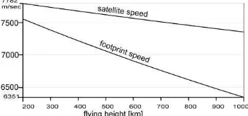
Figure 1. Speed of satellite and footprint speed
Sensor ,
Table 1. Very high resolution optical satellites
The satellite speed depends upon the flying height corresponding to the Keppler law. For practical application the footprint speed – the speed of the satellite orthogonal projected to the earth surface – is more important (figure 1). With the image line can be fitted to the sampling rate.
Figure 2. Asynchronous imaging mode with slow down factor B/A
The slow down factor (table 2) as well as the imaging in another direction is not influencing the scene accuracy. By default all mentioned sensors are imaging in relation to the ground coordinate system which does not correspond to the orbit direction, but imaging in any direction including imaging against the orbit direction is possible. The slow down factor influences only the imaging capacity. WorldView and GeoEye have a sampling rate of 24000 respectively 20000 lines/second
for imaging just with the panchromatic band. This leads to a
Table 2. Sampling rate and slow down factor
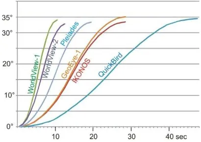
The very high resolution optical satellites are limited to one camera, changing the view direction by a body pointing of the satellite. This is based on reaction wheels or control moment gyros, having fast rotating gyros causing a moment to the satellite if accelerated of slowed down. Reaction wheels are strapped down while control moment gyros have fixed axis in the inertial space. The WorldView satellites have control moment gyros allowing a faster change of the view direction (figure 3).
Figure 3. Slewing time with change of view direction/time
The slewing time directly influences the imaging capacity. A faster slewing increases the possibility of selecting the ground scenes in the range of an orbit as well as improving the stereo imaging capacity. For the slow rotating QuickBird the generation of stereo scenes was not economic because in addition to one stereo scene no other area could be images, this changed drastically with WorldView.
For a free selection of ground scenes not only the slewing speed, also the flying elevation is important. From 770km flying height WorldView-2 can faster change from one ground scene to another as WorldView-1 from 494km height even with the slightly lower slewing speed (figure 6).
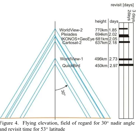
The flying elevation determines directly the revisit time by the field of regard and the fact that for the sun-synchronous orbit the number of orbits per day just depends on the flying height (figure 4 and formula 1). The field of regard is dominated by the accepted incidence angle of the scene, which exceeds the nadir angle (figure 5). For the user the incidence angle is important, this determines the occlusions in build up areas and the size of the
projected pixel on the ground. In view direction the projected pixel size is the GSD at nadir divided by cos² while across the view direction it is the GSD at nadir divided by cos .
Figure 4. Flying elevation, field of regard for 30° nadir angle and revisit time for 53° latitude
The revisit time for the equator Requator can be estimated depending upon the flying elevation with the approximation in formula 1.
Formula 1. Revisit time [days] for the equator and for 30° nadir angle as function of satellite height (hg) [km]
The revisit time depending upon the latitude corresponds to Requatorcos(latitude).
Figure 5. Relation between nadir angle and incidence angle
The field of regard for WorldView-1 and -2 in relation to 30° incidence angle can be seen in figure 6. For the same distance of 259km on the ground WorldView-1 has to rotate 27.6°, while WorldView-2 from the higher flying height has to rotate only 18.6° (figure 6).
Not only the revisit time and the weather conditions are important for getting ordered images, the imaging capacity of the satellites is still dominating. It depends upon storing capacity and download possibilities. As shown in figure 7, the imaging capacity for the latest very high resolution satellites has been strongly increased against the earlier once. In addition to the internal storage the number of ground stations or relay satellites plays a role. This is a major difference to most of the
small satellites having very limited imaging capacity with the extreme case of the South African SumbandilaSat, having 6.25m GSD and 6 spectral bands in the visible spectral range, taking just 93 images within 6 month. In addition it is very difficult to get images for an ordered area with several of the small satellites. An exception is the RapidEye constellation, able to deliver images within a very short time.
Figure 6. field of regard for 30° incidence angle of WorldView-1 (494km flying height) and WorldView-2 (770km flying height)
Figure 7. Theoretical collection capacity for panchromatic images, for panchromatic plus color channels the capacity is
reduced by factor 2
Figure 8. left in red = area of interest, right in red = tasking area dependent upon cloud coverage, satellite slewing speed and
imaging capacity (Zevenbergen 2007)
Figure 8 shows on the left hand side an example of areas of interest for imaging by IKONOS in the swath area of +/-30° incidence angle, corresponding to +/-350km range from the footprint. On right hand side the effectively imaged areas demonstrate the influence of the cloud coverage together with the limitation by changing the view direction. So the theoretical collection capacity usually will not be reached. IKONOS and QuickBird mainly have been schedulled for areas where imaging orders existed. With the quite higher capacity of WorldView and GeoEye-1 an improved possibility to generate complete archives exist. The very high slewing speed of WorldView also improves the possibility to image a higher number of interest areas in the swath area.
3. RADIOMETRIC SITUATION
Not only the geometric specification is important, the radiometric situation is important as well. It starts with the effective resolution. The image quality must not correspond to the nominal ground resolution. As mentioned above, the projected pixel size depends on the incidence angle. Nevertheless images are distributed as Geo, OR Standard or level 2A, projected to a plane with constant height, with a standard GSD, even if this may be smaller or larger as the projected pixel size. In orbit direction the GSD is determined by the sampling rate, the satellite footprint speed and the effect of an asynchronous imaging mode. This GSD must not correspond to the projected pixel size in orbit direction which may be enlarged by the incidence angle component in orbit direction leading to an oversampling. An oversampling also is caused by staggered CCD-lines, shifted in the line half a pixel against each other. Such an oversampling is used by SPOT-5 supermode, distributed with 2.5m GSD even if the projected pixel size for nadir view is 5m. Similar it is with Cartosat -2, -2A and -2B, distributed with 1m GSD based on 2m projected pixel size. Of course this influences the image quality.
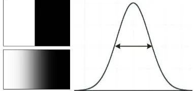
The effective resolution can be determined by edge analysis (Jacobsen 2009). A sudden change of the object reflection at an edge, which may appear with a bright roof neighbored by dark shadow, causes a continuous change of the grey values in the image. A differentiation of the grey value profile leads to the point spread function (Figure 9). The width of the point spread function corresponds to twice the effective resolution.
Figure 9: left: edge in object space and in image space, right: point spread function
Sensor Nominal
GSD
factor Effective GSD
ASTER 15m 1.0 15m
Kompsat-1 6.6m 1.0 6.6m
IRS-1C 5m 1.16 5.8m
SPOT-5 5m 1.0 5m
SPOT-5 supermode 2.5m 1.18 3m
IKONOS 1m 1.0 1m
QuickBird 0.6m 1.0 0.6m
OrbView-3 1m 1.2 1.2m
Resourcesat 5.9m 1.12 6.6m
Cartosat-1 2.5m 1.12/1.28 2.8m/3.2m
ALOS Prism 2.5m 1.08 2.7m
WorldView-1 0.5m 1.0 0.5m
GeoEye-1 0.5m 1.0 0.5m
Table 3. effective ground resolution
Table 3 shows the nominal GSD, the factor determined by edge analysis and the corresponding effective GSD. If the factor for the effective GSD is clearly above 1.0, it is usually caused by staggered CCDs, where the projected pixel size is twice as large as the distance of neighbored pixel centres on the ground. Of course a lower image quality may be caused also by hazy atmosphere, on the other hand the nominal GSD can be
manipulated by contrast enhancement. Most space images are improved by contrast enhancement, reducing the factor for nominal GSD.
Photo 63cm GSD IKONOS GeoEye-1 Figure 10. From left: building in aerial photo 63cm GSD,
IKONOS and GeoEye-1
As it is obvious in figure 10, the shown GeoEye-1-image with 0.5m GSD includes more details as the IKONOS image with 1m GSD, but the aerial photo with 63cm GSD or effectively 74cm GSD is not better as the IKONOS image with 1m GSD. The aerial image is strongly affected by film grain.
Figure 11. Spectral range of panchromatic channel (upper line in grey) and color channels
Figure 12. Spectral sensitivity of IKONOS and QuickBird left and for WorldView-2 right
The latest very high resolution sensors GeoEye-1 and WorldView-2 have against IKONOS and QuickBird a changed characteristic of the panchromatic band cut at approximately 800nm against sensitivity of IKONOS and QuickBird which panchromatic band exceeds 1000nm.
Figure 13 demonstrates the effect of the extended spectral sensitivity to the near infrared range for IKONOS. The trees in the park surrounding the Topkapi palace in Istanbul are dark in the RGB image in relation to the built up area, while they are bright in the near infrared image and corresponding to this in the panchromatic image, including the spectral range of RGB and near infrared. Trees have a similar grey level as the buildup area.
Figure 13. IKONOS: upper left: original RGB-image as grey value image; upper right. Panchromatic image; lower left:
NIR-image; lower right: Original RGB-image
Figure 14: left: standard Brovey pan-sharpening; right: modified Brovey pan-sharpening
(1) Brovey transformation
(2) Modified Brovey transformation
With DNb /DNg /DNr /DNNIR/DNpan = grey value blue / green / red / near infrared / panchromatic
and F = choose able factor with 1.0 as default and MF as correction factor for brightness
The extended panchromatic range of IKONOS causes problems for the generation of pan-sharpened images. If the extended sensitivity in the near infrared range is not respected, the color of the pan-sharpened image generated by Brovey transform (formula 1) is strange as shown in figure 14 left. Only if the influence of the near infrared spectral range is subtracted from the panchromatic band as with the self developed modified Brovey transform (formula 2), the color of the pan-sharpened
image corresponds to the expectation – better as the original RGB-image which is too green. With the panchromatic channel of GeoEye-1 and WorldView-2 the generation of pan-sharpened images with standard methods is simplified.
4. IMAGE ORIENTATION
The image orientation by bias corrected rational polynomial coefficients (RPC) became standard. The direct sensor orientation of the very high resolution satellites, based on GNSS-positions, gyros and star sensors, reached a high level of precision allowing the use without ground control points (GCP) for some application (table 4).
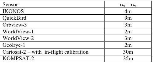
Sensor σx= σy
IKONOS 4m
QuickBird 9m
Orbview-3 3m
WorldView-1 2m
WorldView-2 3m
GeoEye-1 2m
Cartosat-2 – with in-flight calibration 30m
KOMPSAT-2 35m
Table 4. Announced standard deviation of scene orientation not improved by GCP and without influence of terrain relief
Nevertheless for using the full accuracy potential of the satellite images an orientation with GCP by bias corrected RPC is recommended. Also not well known datum parameters of the national net may require the use of GCP.
Sensor, area Level GSD [m]
SX/SY [m]
SX/SY [GSD]
SPOT, Hannover 1B 10 4.6 0.5
SPOT-5, Zonguldak
1B 5 5.2 1.0
SPOT-5, Zonguldak
2A 5 5.1 1.0
SPOT HRS, Bavaria
1B 5x10 6.1 0.7/1.1
IRS-1C, Hannover 1B 5.7 5.1 0.9
Cartosat-1, Warsaw
1B 2.5 1.4 0.8
OrbView-3, Zongudak
1B 1 (2) 1.3 1.3
IKONOS, Zonguldak
2A 1 0.7 0.7
QuickBird, Zonguldak
2A 0.61 0.5 0.8
WorldView-1, Istanbul
2A 0.5 0.45 0.9
GeoEye-1, Riyadh 2A 0.5 0.4 0.8
Table 5. Standard deviation of sensor orientation at check points based on geometric reconstruction or bias corrected sensor oriented RPC-solution; 1B=original images, 2A=images projected to plane with constant height as IKONOS Geo
Table 5 shows root mean square errors at independent check points of scene orientations with basic imagery (level 1B in the definition of SPOT) and Geo or OR Standard (level 2A in the definition of SPOT). Independent upon the type of imagery and the method of orientation based on bias corrected RPC or geometric reconstruction, accuracy of one GSD or better was reached. Only the accuracy achieved with OrbView-3 was slightly worse, but this can be explained by the limited image
quality caused by the staggered CCD-lines. The dominating influence always is the quality of control and check point identification.
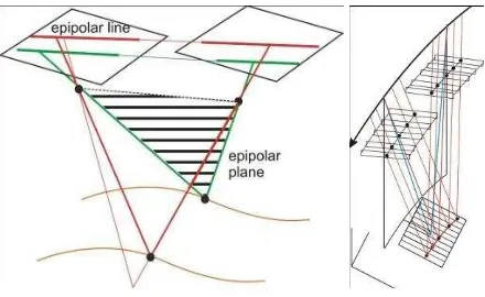
5. EPIPOLAR IMAGES
As mentioned above, the flexible optical satellites can take stereo pairs within the same orbit having just approximately 1 minute difference in time. These stereo pairs are optimal for the generation of digital elevation models (Alobeid et al. 2011). The automatic image matching is simplified by epipolar images, reducing the search for corresponding points to the epipolar lines. Some image matching methods as semiglobal matching and pixel based matching with dynamic programming require such epipolar images. Epipolar image pairs partially can be ordered, but it is simple to generate quasi epipolar image pairs with Geo or orthoready standard images.
Epipolar lines of perspective images are the intersection of the epipolar plane, defined by the object point and both projection centers, with the images (figure 15 left). Line scanner images have perspective geometry only in the line, in the other direction for any line there is a different projection centre (figure 15 right). For satellite basic imagery (level 1A) the transformation to epipolar images is complex and can be computed iteratively. In the case of Geo or OR Standard images (level 2A) in a flat area the image space is identical to the object space, so the transformation of the image to epipolar geometry is just a two-dimensional problem. Images taken in the nadir view only have to be rotated to the base direction for the transformation into epipolar geometry. The error caused by the approximation of the epipolar satellite line scanner images generated just by rotating the level 2A-type images into the base direction depends upon the difference in the view direction component across the orbit direction. This depends upon the height change of the orbit against the tangential plane of the orbit going through the projection centre of the scene centre – for a distance of 15km, corresponding to a scene length of 30km, the height difference is 15²km²/14092km = 16m (h=D²/(2R)). For a view 45° across the orbit, the component in view direction is 16m * sin 45° = 11.3m. To the epipolar image this has an influence depending upon the object height against the reference plane of the scene. For 500m difference and the orbit height of IKONOS or GeoEye-1 of 682km, the influence to the epipolar image in object space is 11.3m * 500m / 682000m = 8mm. The 8mm have to be seen in relation to the GSD of 50cm or 1m respectively; that means even under extreme conditions the approximation of epipolar image generation just by rotation to the base direction is negligible. The remaining y-parallax was always quite below one pixel.
Figure 15.Left: Epipolar lines in perspective images, Right: Epipolar geometry for line scanner images
The base direction can be computed with the nominal satellite elevation and azimuth of both images of a stereo pair, available in the metadata file, together with the satellite flying height.
6. CONCLUSION
Very high resolution optical space images today can be ordered without problems thanks to the strongly improved imaging capacity of the space systems and the improved satellite flexibility. The image quality always is good, similar to digital aerial images and better as for analog aerial photos with corresponding GSD.
The spectral range of the panchromatic band of GeoEye-1 and WorldView-2 has been reduced against previous optical satellites, simplifying the pan-sharpening, but nevertheless also with the other satellite images with stronger sensitivity in the near infrared range, qualified pan-sharpened images can be generated if the influence of the near infrared range is subtracted from the panchromatic band.
The image orientation has been simplified by RPCs and the direct sensor orientation has been improved, allowing also in some cases the use without GCPs.
The improved rotation speed simplified the generation of stereo pairs taken from the same orbit. Automatic image matching for the determination of digital surface models can be supported by epipolar images which simply can be achieved by the rotation of Geo or orthoready standard images (level 2A) to the direction of the image base.
REFERENCES
Alobeid, A., Jacobsen, K., Heipke, C., 2010: Comparison of Matching Algorithms for DSM Generation in Urban Areas from IKONOS Imagery, PERS 76(9). pp. 1041-1050
Alobeid, A., Jacobsen, K., Heipke, C., Al Rajhi, M., 2011: Building Monitoring with Differential DSMs, ISPRS Hannover Workshop 2011
Jacobsen, K., Büyüksalih, G., Baz, I., 2008: Mapping from space for developing countries, EARSel Workshop Remote Sensing - New Challenges of High Resolution, Bochum 2008, http://www.earsel.org/workshops/HighRes2008/Artikel/12_Jaco bsen.pdf
Jacobsen, K., 2009. Effective resolution of digital frame images, ISPRS Hannover Workshop 2009. In: The International Archives of the Photogrammetry, Remote Sensing and Spatial Information Sciences, Vol. XXXVIII-1-4-7/W5.
Zevenbergen, A., 2007. IKONOS&GeoEye-1, Ground Segment Coordination Body workshop, Frascati, June 19 & 20, 2007