MEASUREMENT LONG MESSAGE SERVICE WITH UNIVERSAL
SOFTWARE RADIO PERIPHERAL (USRP)
Hafidudin
1), Agus Ganda Permana
2), Muhammad Iqbal
3)1), 2) 3)
Program Studi Diploma 3 Teknik Telekomunikasi Fakultas Ilmu Terapan Universitas Telkom Bandung Jl Telekomunikasi No.1,Terusan Buah Batu, Bandung, Jawa Barat 40257
Email :[email protected]), [email protected]2),[email protected]3)
Abstrak
Abstract - Telecommunication world is increase growing rapidly. Almost everyone in this world has a mobile communication device. It can’t be separated from the BTS (Base Transceiver Station) function which become the key of communication. Because the development of technology, appear the latest technology called USRP (Universal Software Radio Peripheral). USRP is device to connected with OpenBTS technology makes user can call and send SMS for free. This technology is very suitable for remote areas which lack of infrastructure telecommunication and for post-disaster area. SMS has special attraction for user, causes the retention of the service and low access cost for users. Moreover, the use of SMS has been extended to variety of necessary.
In this topic research, implemented technology USRP and SMS service with purpose to optimizing the functional of OpenBTS which is usually only be used for voice service only. GNURadio and USRP as regulator for running OpenBTS. For running the SMS service use Smqueue which already available on OpenBTS software.
From scenario testing, for SMS service use OpenBTS better than use GSM operator, with delay 2 -3 second. OpenBTS support LMS (Long Message Service) no support more than 480 character.
Keyword : LMS, USRP, OpenBTS, and SMS
1. Introduction
Computer technology is currently being developed or are developing software that is often called open source. One of the open source development of the ability to make a software that can create their own base stations, which is very useful for mobile phone users.
OpenBTS is a software-based GSM technology that runs on linux platform. This technology is an alternative solution for remote areas and post-disaster telecommunications infrastrukutur damaged. In the previous OpenBTS only perform the function for local voice services using VoIP premises.
The number of GSM operators that have been developed, causing the cost of sending an SMS competition is diverse, there are more expensive. One of the technologies that become OpenBTS feature is SMS (Short Message Service) is used to convey information quickly. By using
OpenBTS, SMS delivery costs not only be less expensive, even be free.
It is clear that mobile phone usage has become one of the most prevalent means of communication worldwide. This number has been steadily increasing over the last 10 years, with growth over the last five years primarily driven by subscriptions in the developing world.[1]
The number of SMS messages is rapidly growing. The increasing demand for data messages services will require future cellular networks to provide efficient and low cost data services[2]. Unfortunately, since the existing cellular networks were built to support a continues, bi-directional traffic (e.g. voice applications), the data link layer protocols used in these networks, such as TDMA and CDMA, cannot efficiently support short data transmissions. Since the main goal of these protocols is to support voice applications, the efficiency of transmitting a single short packet using these protocols is very poor. For this reason, SMS messages in cellular net-works are currently transmitted through the signaling channel. Unfortunately, this channel is probably the most precious wireless resource of a cellular network. Moreover, the access protocol to this channel is the slotted ALOHA, which is not stable. Under conditions of high load, the efficiency of slotted ALOHA is very poor, and SMS messages may even block the signaling channel. There is therefore a need either to utilize the shared signaling channel more efficiently, or to use another shared channel, dedicated to data messages transmissions. It is desirable to use for either purpose, a multiple access protocol which is robust and reliable, yet efficiency
2. Literatur Review
2.1. Global System for Mobile Communication Global System for Mobile communication (GSM), also known as the second-generation cellular system standard, originated from Pan-Europe in 1987, and the first network was established in Geneva in 1991. Since that time, it started spreading worldwide, until it became one of the most famous digital communications system nowadays, reaching more than 4.6 billion users.
GSM came after the first generation to solve the latter’s fragmentation issues. Moreover, it was the first cellular system that uses digital modulation.
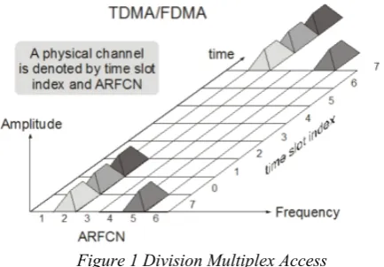
MHz. However, the 900 MHz range is the most used one. It uses FDD for duplexing with a duplex spacing of 45 MHz at 900 MHz. Actually, the frequency range specified is divided into two bands: 890-915 MHz for uplink and 935-960 MHz for downlink. Moreover, this 25 MHz bandwidth is divided into 125 channels, 200 KHz each. One channel is used by the base station to manage and control the network. Each channel from the 124 other channels is divided into 8 time slots in order to serve 992 simultaneous active users (124*8 = 992).[3]
Figure 1 Division Multiplex Access
Basically, the GSM system is divided into three sections:
a) Network and Switching Subsystem (NSS) implemented by the Mobile-services Switching Center (MSC).
b) Basic Station Subsystem (BSS) consisted of the Base System Controller (BSC), the Base Transceiver System (BTS) and the Mobile System (MS).
c) Operation Support Subsystem (OSS) implemented by the Operation Maintenance Center (OMC) and the system software. [6]
The BSS, which we are trying to build in our project, interfaces the MSs (mobile phones in our case) over the radio interface. Another interface is needed, the A-interface or A-bis-A-interface, between the BSS and the MSC when a network of several BSSs is built. One BSS can have one BSC along with several BTSs at the same time to cover different cells of the cellular system. Also, the BTS itself might have more than one transceiver to cover only one cell. Transceivers of the same BTS should have the same Base Station Identity Code that identifies the corresponding cell.
2.2 GSM Network Architecture
The GSM network is composed of several parts which have the function of each, and is divided into:
a) Mobile Station (MS)
MS is a device used by customers to have the conversation. MS is divided into two, namely:
• Mobile Equipment (ME) or handset, a GSM device
users who are on the side that serves as a terminal transceiver.
• Subscriber Identity Module (SIM) card, a card that contains all customer information and some
information services. ME can not engage without a SIM in it.
b) Base Station Subsystem (BSS) Consisting of:
• Base Transceiver Station (BTS), a GSM device
connected directly to the MS, serves as a signal sender and receiver, and arrange the handover is controlled by the BSC.
• Base Station Controller (BSC), a device that controls
the performance of base stations and MSC liaise with BTS.
c) Network Subsystem (NSS) Network Subsystem consists of:
• Mobile Switching Center (MSC), is a central network elements in a GSM network. MSC as a cellular network core, and serves to interconnect the relationship talk.
• Home Location Register (HLR), serves as a database to store all the data that the customer information is stored permanently.
• Visitor Location Register (VLR), serves to store data
and customer information temporarily.
• Authentication Center (AuC), which is necessary to store all the data required to check the validity of the customer. So that the customer talks unauthorized inevitable.
• Equipment Identity Registration (EIR), which contains customer data.
d) Operation and Support System (OSS)
A sub-system of the GSM network that serves as a control center, including fault management, configuration management, performance management, and inventory management.
2.3 OpenBTS
Litteraly, OpenBTS is an open Base Transceiver Station, where a BTS is the telecom equipment the closesest to the mobile phone. GSM phones can call each other, send SMS to each other etc. From an inner perspective, OpenBTS’s explains it quite well: ”OpenBTS replaces the traditional GSM operator network switching subsystem infrastructure, from the Base Transceiver Station (BTS) upwards. Instead of forwarding call traffic through to an oper- ator’s mobile switching centre (MSC) the calls are terminated on the same box by forwarding the data onto the Asterisk PBX via SIP and Voice-over-IP (VoIP).” [4] From an administrator’s point of view, OpenBTS consists of a Universal Software Radio Peripheral (USRP) board, connected on a USB port of a Linux box running Asterisk/Yate, GnuRadio and OpenBTS.
traffic terminated in the same box by way of forwarding the data to the Asterisk PBX through SIP and Voice-over-IP (VoVoice-over-IP). Heart OpenBTS itself is actually GNU Radio applications, serves as the controller USRP. For traffic management and sound (voice) applications use Asterisk (VoIP protocol SIP). The function of Asterisk is similar to the device (hardware) MSC (Mobile Switching Centre) in the GSM system.
2.4 Long Message Service (LMS)
SMS is a service that is able to send and receive text messages to and from mobile devices. SMS is a messaging service that is generally contained on any digital wireless network system. A text message is composed of letters, numbers, or alphanumeric character. Text messages packed in one packet / frame with a capacity of a maximum of 160 bytes which can be 160 characters to representated in Latin letters or 70 non-Latin alphabet characters such as Arabic or Chinese characters. Transmission of SMS network using signaling channel, not channel sound, so we still can receive text messages even while doing voice communication.
Larger content (concatenated SMS, multipart or segmented SMS, or "long SMS") can be sent using multiple messages, in which case each message will start with a User Data Header (UDH) containing segmentation information. Since UDH is part of the payload, the number of available characters per segment is lower: 153 for 7-bit encoding, 134 for 8-bit encoding and 67 for 16-bit encoding. The receiving handset is then responsible for reassembling the message and presenting it to the user as one long message. While the standard theoretically permits up to 255 segments, 6 to 8 segment messages are the practical maximum, and long messages are often billed as equivalent to multiple SMS messages. Some providers have offered length-oriented pricing schemes for messages, however, the phenomenon is disappearing.
2.5 SMS Architecture
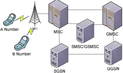
SMS/LMS messages are transmit via the Common Channel Signaling System 7 (SS7) and Sigtran. SS7 is a global standard that defines the procedures and protocols for exchanging information among network elements of wireline and wireless telephone carriers. These network elements use the SS7 standard to exchange control information for call setup, routing, mobility management, etc [5]. Figure 2.2 shows the typical network architecture for SMS communication.
Conceptually, the network architecture consists of two segments that are central to the SMS model of operation: the Mobile Originating (MO) part, which includes the mobile handset of the sender, a base station that provides the radio infrastructure for wireless communications, and the originating Mobile Switching Center (MSC) that routes and switches all traffic into and out of the cellular system on behalf of the sender. The other segment, the Mobile Terminating (MT) part, includes a base station and the terminating MSC for the receiver, as well as a centralized store-and-forward server known as SMS Center (SMSC). The SMSC is responsible
for accepting and storing messages, retrieving account status, and forwarding messages to the intended recipients. It is assisted by two databases: the Home Location Registrar (HLR) and the Visitor Location Registrar (VLR). The two databases contain respectively permanent and temporary mobile subscriber information, e.g., the address of the MSC the device is associated with. [6]
Figure 2 Architecture SMS Communication
Though the Short Message Service has been popularized by the exchange of text messages among cell phone users, it has been increasingly used by businesses as a low-cost bearer to deliver various types of content such as ringtones, news, stock price, quizzes, and casting of votes. Such content providers, also known as External Short Message Entities (ESMEs), initiate or receive text messages through gateways which bridge the SMS interface to the Internet.
2.6 USRP
USRP2 allows the creation of a software radio with any computer having gigabit Ethernet interface. It’s the upgraded version of its earlier release USRP. USRP has a USB interface limiting the data throughput from USRP to Computer at a maximum bandwidth of 8MHz. The design of USRP and USRP2 is open source and all schematics and component information can be downloaded from the website of the manufacturer. USRP2 contains field programmable gate arrays (FPGA) and RF transceiver board which is connected over FPGA.[7]
The main idea behind the design of USRP is to perform all the signal processing tasks for example modulation and demodulation, filtering at the host computer. All the general purpose tasks such as decimation, interpolation, digital up conversion and down conversion are performed inside the FPGA of USRP2. USRP2 contains gigabit Ethernet controller, SD card slot and MIMO expansion slot at the front end with 8 LED indicators. SD card contains the driver for USRP2 mother board and RF transceiver. It requires 5V DC and 6A to power up USRP2.
Ethernet. This connection allows the software to control the USRP and prepare signals to send and receive data.
Figure 3 USRP 2
2.7 USRP2 Operation with GNU Radio
USRP2 operation with GNU Radio can be explained RF transceiver fetches the RF signal from real time environment and converts it to Intermediate Frequency (IF) around direct current (DC). After converting it to IF the signal is passed to ADC. USRP2 contains two 14-bit ADC which provides sampling rate of 100MS/s [7]. The ADC after sampling passes the data to FPGA. The main task for the FPGA is the down conversion of remaining frequency and data rate conversion. After processing, FPGA transfers the results to gigabit Ethernet controller which passes it over to the host computer where the rest of the signal processing tasks are performed. In case of transmission the same procedure is repeated in reverse order. Firstly gigabit Ethernet controller of host computer passes the input parameters to USRP2. After receiving, the complex signal, digital up converter (DUC) converts the signal to IF before passing it to DAC. The DAC passes the IF converted signal to the RF transceiver where it is converted to RF signal and transmitted over the air.
Figure 4 USRP Operation
3. Implementation
Physical topology of the system to be constructed as shown in figure 3.1. In the above network implementation used the following devices:
1.1. Hardware
a. Laptop: Specifications: HP ProBook 4420s, Intel Core i3, 4 GB RAM, 320GB hard drive with Ubuntu Linux Operating System LTS 12:04. b. USRP Specifications : USRP 2 with 900 Vert
antenna (85 db) USB 2.0 with a 52 MHz clock rate.
c. Mobile Phone Specification : Samsung Galaxy Tab 2 & Blackberry Javeline.
d. SIM Card Specifications: Telkomsel (Anything).
Figure 5 Architecture Network
1.2. Software
a. 12:04 LTS Ubuntu Linux as the operating system used.
b. GNURadio 3.4.2, Yate 5.0.0, OpenBTS 2.8 as forming OpenBTS software.
c. Wireshark as displays packets passing through the network interface card of the computer along with the time when the package is passed. d. Yate Client
2. INSTALATION AND SYSTEM
CONFIGURATION
2.1.
Configure USRP Hardware
At the beginning of the research performed on the device configuration USRP as open BTS. At this stage a separate stand-alone configuration with a PC just configure USRP devices only. Here are some of the configuration is done:
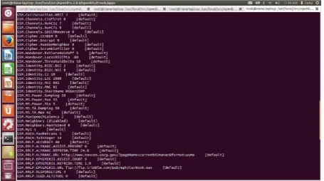
2.2. USRP Detection
This configuration performed in a way to detect mobile phones and network registration for SIP signaling between the source to the destination during the phase of VoIP calls, packet size and the type of information each protocol can be seen in the capture. The following figure is the result of USRP capture detection on mobile phones:
Figure 7 Network Carrier
2.3. SMS LOG
After configuring the device and ensure interconnection with the server, then performed LOG SMS to test that a cell phone that has been registered on the USRP can make sending SMS. Here are the results of the capture of the SMS log:
Gambar 8. SMS Log
3. TESTING AND MEASUREMENT
3.1. The objective Measurement
To determine the quality of the transmission of SMS services on the network OpenBTS one of the important parameters is the unknown delay SMS. And because of the limited functionality of SMS services, should be done anyway measurement capabilities of the SMS service.
3.2. Measurement Scenario
This measurement uses 2 mobile phones which are connected to the OpenBTS network, then the second MS exchanging SMS. Measurements were made using several scenarios, namely:
a. Measurement of the SMS delay between user OpenBTS
b. Sending SMS 8 bits
c. Delivery LMS (Long Message Service)
3.3.
Measurement Results
5.3.1
Delay
The results of measurements of delay between user OpenBTS and compared with the delivery of a normal GSM network operator. From the measurement results of the SMS delay in figure 9 shows that the inter-user OpenBTS with a delay time less than GSM users with an average of 2-3% of SMS delivery time. This is because at the time of measurement USRP is placed close to the MS so that the resulting signal quality is very good compared to the use of GSM operators.
Figure 9 SMS Delay Graph
5.3.2
SMS 8 bits
By default SMS is currently categorized as a 7-bit SMS. The purpose of the SMS standard 7 bits are used for English letters (UK) including those used by Indonesia. Smqueue on OpenBTS system version 4.0
OpenBTS Operator
GSM
Delay 2 5,1
0 1 2 3 4 5 6
se
co
n
d
supports sending SMS in the form of 8-bit symbols. These symbols are sometimes not supported to certain types of mobile phones. If the device does not support the mobile receiver, the symbol will change to a box or changed to other symbols.
5.3.3
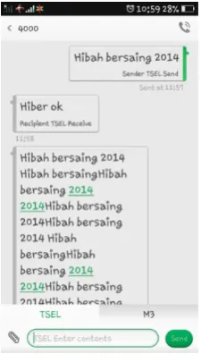
Trial LMS (Long Message Service)
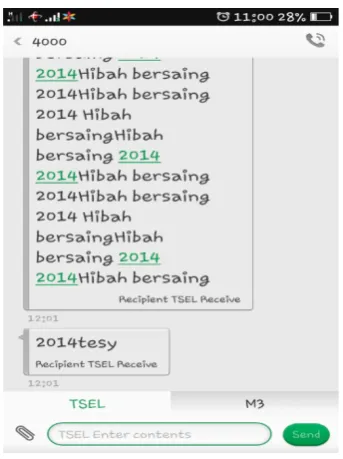
Figure 10 SMS
Figure 11 LMS Start
Figure 12 LMS end
In the figure above shows the process of communication between a mobile phone with another phone using USRP, addressing a new phone number for both the mobile phone is 1200 and 4000, so the messaging communication process can run well
Each of the SMS usually only have 160 characters, but called the LMS or Long Message Service has the ability to send more than 160 characters. OpenBTS LMS supports the delivery of this but can only be done to a fellow user OpenBTS. The length of characters that can be delivered includes 480 characters and can be received by other users for 30 seconds. Delivery process longer because smqueue can not directly process and transmit 480 characters simultaneously, because the OpenBTS done by sending the SMS 160 characters and will be sent again the rest of the character of the SMS sent.
Smqueue also supports the delivery of LMS (Long Message Service) but limited to 480 characters. When sending 160 characters, the time it takes as much as 2-3 seconds. When the characters to 320 characters, the time it takes as much as 30-45 seconds. While sending 480 characters, the time it takes as much as 1 minute
4.
CONCLUSION
Based on the results of the implementation process, testing, and analysis it can be concluded as follows: 1. OpenBTS has been successfully implemented as
evidenced by the success of voice and SMS communication links.
2. For sending a message through the OpenBTS, delay smaller than that obtained through the normal GSM operators.
4. Smqueue also supports the delivery of LMS (Long Message Service) but limited to 480 characters. When sending 160 characters, the time it takes as much as 2-3 seconds. When the characters to 320 characters, the time it takes as much as 30-45 seconds. While sending 480 characters, the time it takes as much as 1 minute.
REFERENCES
[1] M. Zheleva, A. Paul, D. L. Johnson, and E. Belding, “Kwiizya : Local Cellular Network Services in Remote Areas,” no. July, 2012. [2] Z. Naor, “An Efficient Short Messages Transmission,” vol. 00, no.
C, 2004.
[3] T. Hajar, W. Saab, and T. Sakakini, “NI USRP GSM Base Station,” 1991.
[4] A. Apvrille, “OpenBTS for dummies,” pp. 1–40, 2013.
[5] X. Meng, “Analysis of the Reliability of a Nationwide Short Message Service,” 2005.
[6] J. Brown, B. Shipman, and R. Vetter, “SMS: The Short Message Service,” 2007.
[7] A. Aftab, “Spectrum Sensing Through Implementation of USRP2,”
no. November, 2010.
Author Biodata
Hafidudin, obtaining a Bachelor of Engineering (ST), Department of Electrical Engineering-Telecommu-nications Institute of Technology Surabaya November, graduating in 1995. He holds a Master of Engineering (MT) Graduate Program Master of Information Systems Telecommunications Bandung Institute of Technology, graduating in 2001. Currently a lecturer in Faculty of Applied Sciences University of Telkom
Agus Ganda Permana, obtaining a Bachelor of Engineering, Department of Electrical Engineering National Institute of Science Technology Jakarta, graduating in 1991. He holds a Master of Engineering (MT) Post Graduate Program in Electrical Engineering Master of Science Technology-Telecommunications Institute of Technology National Jakarta, graduating in 2004. Currently a lecturer in the Faculty Telkom University of Applied Sciences