Corporat e Headquart ers Cisco System s, Inc.
170 West Tasm an Drive San Jose, CA 95134-1706 USA
http://w w w .cisco.com Tel: 408 526-4000
800 553-NETS (6387) Fax: 408 526-4100
Cisco Technical Solut ion Series:
IP Telephony Solut ion Guide
THE SPECIFICATIONS AND INFORMATION REGARDING THE PRODUCTS IN THIS MANUAL ARE SUBJECT TO CHANGE WITHOUT NOTICE. ALL STATEMENTS, INFORMATION, AND RECOMMENDATIONS IN THIS MANUAL ARE BELIEVED TO BE ACCURATE BUT ARE PRESENTED WITHOUT WARRANTY OF ANY KIND, EXPRESS OR IMPLIED. USERS MUST TAKE FULL RESPONSIBILITY FOR THEIR APPLICATION OF ANY PRODUCTS.
THE SOFTWARE LICENSE AND LIMITED WARRANTY FOR THE ACCOMPANYING PRODUCT ARE SET FORTH IN THE INFORMATION PACKET THAT SHIPPED WITH THE PRODUCT AND ARE INCORPORATED HEREIN BY THIS REFERENCE. IF YOU ARE UNABLE TO LOCATE THE SOFTWARE LICENSE OR LIMITED WARRANTY, CONTACT YOUR CISCO REPRESENTATIVE FOR A COPY.
The Cisco implementation of TCP header compression is an adaptation of a program developed by the University of California, Berkeley (UCB) as part of UCB’s public domain version of the UNIX operating system. All rights reserved. Copyright © 1981, Regents of the University of California.
NOTWITHSTANDING ANY OTHER WARRANTY HEREIN, ALL DOCUMENT FILES AND SOFTWARE OF THESE SUPPLIERS ARE PROVIDED “AS IS” WITH ALL FAULTS. CISCO AND THE ABOVE-NAMED SUPPLIERS DISCLAIM ALL WARRANTIES, EXPRESSED OR IMPLIED, INCLUDING, WITHOUT LIMITATION, THOSE OF MERCHANTABILITY, FITNESS FOR A PARTICULAR PURPOSE AND
NONINFRINGEMENT OR ARISING FROM A COURSE OF DEALING, USAGE, OR TRADE PRACTICE.
IN NO EVENT SHALL CISCO OR ITS SUPPLIERS BE LIABLE FOR ANY INDIRECT, SPECIAL, CONSEQUENTIAL, OR INCIDENTAL DAMAGES, INCLUDING, WITHOUT LIMITATION, LOST PROFITS OR LOSS OR DAMAGE TO DATA ARISING OUT OF THE USE OR INABILITY TO USE THIS MANUAL, EVEN IF CISCO OR ITS SUPPLIERS HAVE BEEN ADVISED OF THE POSSIBILITY OF SUCH DAMAGES.
AccessPath, AtmDirector, Browse with Me, CCIP, CCSI, CD-PAC, CiscoLink, the Cisco Powered Network logo, Cisco Systems Networking Academy, the Cisco Systems Networking Academy logo, Fast Step, Follow Me Browsing, FormShare, FrameShare, GigaStack, IGX, Internet Quotient, IP/VC, iQ Breakthrough, iQ Expertise, iQ FastTrack, the iQ Logo, iQ Net Readiness Scorecard, MGX, the Networkers logo, Packet, RateMUX, ScriptBuilder, ScriptShare, SlideCast, SMARTnet, TransPath, Unity, Voice LAN, Wavelength Router, and WebViewer are trademarks of Cisco Systems, Inc.; Changing the Way We Work, Live, Play, and Learn, Discover All That’s Possible, and Empowering the Internet Generation, are service marks of Cisco Systems, Inc.; and Aironet, ASIST, BPX, Catalyst, CCDA, CCDP, CCIE, CCNA, CCNP, Cisco, the Cisco Certified Internetwork Expert logo, Cisco IOS, the Cisco IOS logo, Cisco Press, Cisco Systems, Cisco Systems Capital, the Cisco Systems logo, Enterprise/Solver, EtherChannel, EtherSwitch, FastHub, FastSwitch, IOS, IP/TV, LightStream, MICA, Network Registrar, PIX, Post-Routing, Pre-Routing, Registrar, StrataView Plus, Stratm, SwitchProbe, TeleRouter, and VCO are registered trademarks of Cisco Systems, Inc. and/or its affiliates in the U.S. and certain other countries.
All other trademarks mentioned in this document or Web site are the property of their respective owners. The use of the word partner does not imply a partnership relationship between Cisco and any other company. (0108R)
Cisco Technical Solution Series: IP Telephony Solution Guide Copyright © 2001, Cisco Systems, Inc.
C H A P T E R 1
Introduction to IP Telephony
1-1Overview 1-1
Organization 1-1
Audience 1-2
Scope 1-2
Revision History 1-2
Related Information 1-3
C H A P T E R 2
IP Telephony Architecture Overview
2-1C H A P T E R 3
Planning the IP Telephony Netw ork
3-1In this Chapter 3-1
Related Information 3-1
Evaluating and Documenting the Existing Data Infrastructure 3-1 LAN/ Campus Environment 3-2
W AN Environment 3-7
Evaluating and Documenting the Existing Telecom Infrastructure 3-10 Examining the Existing Telecom Topology 3-11
Examining PBX and Key Systems 3-12 Examining Voice M ail Systems 3-12 Examining Voice Trunking 3-12
Phones per Site and Phone Features 3-17 Examining the Existing Dial Plan 3-17 Fax Requirements 3-21
Evaluating and Documenting the Existing Pow er/ Cabling Infrastructure 3-21 Data Center Pow er Requirements 3-22
W iring Closet Pow er 3-23
IP Telephony Availability Requirements 3-24 Hardw are Reliability 3-25
Softw are Reliability 3-26 Link/ Carrier Availability 3-27 Pow er/ Environment 3-29 Netw ork Design 3-31 User Error and Process 3-33
Planning for W AN Deployments 3-34
Collecting Information on the Current W AN Environment 3-34 Determining Voice Bandw idth Requirements 3-38
Performing Upgrades and Implementing Tuning 3-43 Assessing Results 3-43
Operational Turnover and Production 3-44
Operations and Implementation Planning 3-44 IP Telephony Capacity Planning 3-44 Solution M anageability Requirements 3-48
Staffing and Expertise Requirements 3-51 Operations Support Plan 3-56
C H A P T E R 4
Designing the IP Telephony Netw ork
4-1In this Chapter 4-1
Related Information 4-1
Overview 4-2
Introduction to IP Telephony Design 4-2
Designing the Campus Infrastructure 4-2
Designing for LAN/ W AN QoS 4-2 The Importance of QoS 4-2 Connecting the IP Phone 4-8
Enabling the High Speed Campus 4-17 Building a Branch Office 4-42
Enabling the W ide Area Netw ork 4-47 Summary 4-72
Designing Cisco CallM anager Clusters 4-73
Selecting Gatew ays 4-73
Dial Plan Architecture and Configuration 4-73
Designing a M ulti-site W AN w ith Distributed Call Processing 4-73
Designing a M ulti-site W AN w ith Centralized Call Processing 4-73
Catalyst DSP Provisioning 4-73
Cisco Packet Fax and M odem Support Guidelines 4-73 Cisco IOS VoIP Router Gatew ays 4-74
Cisco VG200 4-75
Catalyst 6000 VoIP Gatew ays 4-76 DT-24+/ DT-30+ Gatew ays 4-77 Future T.38 Fax-relay Support 4-77
E911 and 911 Emergency Services 4-78 Today’s E9-1-1 Service 4-78
Infrastructure Security Best Practices 4-87 Securing CallM anager Servers 4-95
Integrating Voice M ail 4-107
Voice M essaging w ith Cisco uOne 4.1E 4-107 Integrating SM DI Voice M ail 4-108
Integrating SM DI Voice M ail Over IP W AN 4-139
M igrating to an IP Telephony Netw ork 4-142
C H A P T E R 5
Implementing the IP Telephony Netw ork
5-1In this Chapter 5-1
Related Information 5-1
Preparing for Implementation 5-2 General Site Information 5-2
Conducting the Site Survey 5-7 Site Survey Tables 5-7
Determining Site Requirements 5-9 LAN Requirements 5-9 W AN Requirements 5-10
Validating Implementation Readiness 5-18 Solution Design Review 5-19
Netw ork Topology Analysis 5-19 Voice Netw ork Analysis 5-19 Data Netw ork Analysis 5-20
Solution Implementation Templates 5-24 Customer Ordered Equipment 5-30
Customer Premises Equipment (CPE) Interface 5-31 Customer Site Readiness 5-31
Implementing the Solution 5-31 Unpacking the Equipment 5-32
Verifying Cabinet Pow er Feeds, Rails, and Earthing 5-32 Physically Installing Equipment in Cabinet 5-32
Recording Equipment Serial Numbers 5-33 Verifying Equipment Slot Allocations 5-33 Installing Intra-Cabinet Pow er Cables 5-33
Installing Intra- and Inter-Cabinet Communications Cables 5-33 Verifying Circuit Termination in Customer Patch Panel 5-33 Pow ering Up Cisco Equipment 5-34
Implementing the Dial Plan 5-34 Configuring E-911 5-36
Conducting Installation Tests 5-47 Fallback Procedures 5-47
Implementing a M igration Strategy 5-47
M igrating from a TDM Netw ork to Cisco IP Telephony Solution 5-48
Upgrading Cisco CallM anager 5-48 M igration Phases 5-48
Solution Implementation Acceptance Testing 5-49 Verification Process 5-49
Acceptance Criteria 5-50
Post-implementation Documentation 5-51 Asset Tag and Cable Labeling 5-51 Customer Acceptance Certification 5-51
Completing the Implementation Reports 5-52
Case Studies 5-52
C H A P T E R 6
Operating the IP Telephony Netw ork
6-1Related Information 6-1
Operations Support and Planning 6-1
Defining Technical Goals and Constraints 6-2 Service Level Goals 6-5
Determining the Relevant Parties 6-6 Defining Service Elements 6-6 Staffing and Support M odel 6-23
Documenting and Approving the Operations Support Plan 6-25
Netw ork M anagement 6-25
Functional Areas of Netw ork M anagement 6-25 Netw ork M anagement Solutions 6-26
Netw ork M anagement Architecture 6-29
M anaging Voice Over IP Netw ork and Element Layers 6-32 NM S Reference Architecture 6-62
M anaging Cisco CallM anager w ith CISCO-CCM -M IB 6-65 Summary of IP Telephony Netw ork M anagement Products 6-67
Securing the CallM anager Server 6-93
Troubleshooting IP Telephony Netw orks 6-103 Troubleshooting Tools 6-103
Troubleshooting Cisco CallM anager Devices 6-115 Call Detail Records 6-167
A P P E N D I X A
Cisco ICS 7750 and Cisco CallM anager 3.1
A-1IP Telephony Requirement Analysis A-1
C H A P T E R
1
Introduction to IP Telephony
Overview
The Cisco IP Telephony Solution Guide is intended to help organizations implement and manage IP Telephony network solutions, which includes Planning, Design, Implementation, and Operations network phases. This method is called the PDIO model. Cisco experts in IP Telephony design, network design, customer support, high availability, network management, network implementation, and traditional telecom systems collaborated to create this document so that you can reduce guesswork, technical resources, and the time needed to ensure successful implementation of a Cisco IP Telephony network.
Organization
This solution guide consists of the following sections:
• Introduction to IP Telephony - provides a brief introduction to this manual.
• Chapter 2, “IP Telephony Architecture Overview” provides a general description of the IP Telephony architecture.
• Chapter 3, “Planning the IP Telephony Network” provides information necessary for planning IP Telephony solutions.
• Chapter 4, “Designing the IP Telephony Network” provides detailed design specifications for building IP Telephony networks.
• Chapter 5, “Implementing the IP Telephony Network” provides important information for successfully implementing IP Telephony.
• Chapter 6, “Operating the IP Telephony Network” provides information for successfully operating, networking, securing, and troubleshooting IP Telephony networks.
Audience
The Cisco IP Telephony Solution Guide is intended for the following audiences:
• Cisco customers involved with the planning, technical design, implementation, and operation of IP Telephony solutions
• Technical management or network planning personnel
• Cisco Sales Engineers, Technical Support Engineers, Cisco Professional Services, and Cisco Support Partners
This document also assumes some technical knowledge of Cisco switching, routing, Quality of Service, CallManager functionality, gateway functionality, and voice signaling principles.
Scope
The Cisco IP Telephony Solution Guide discusses the core components of the IP Telephony network:
• Current data network design for IP Telephony
• CallManager version 3.0
• Gateways supported under the current IP Telephony architecture
• Voice mail systems
The following applications are not discussed:
• uONE unified messaging
• TAPI or JTAPI
Contact your Cisco representative or visit the following Cisco website for available information on IP Telephony solution applications not covered in this solution guide:
www.cisco.com.
Revision History
Table 1-1 Cisco IP Telephony Solution Guide Revision History
Version Date New /Changed Content
Version 2.1 October 2001 • Added ICS 7750 information and IP Telephony case study links
• Adjusted entries in Tables 3-19
• Added Appendix A Version 2.0 June 2001
Related Information
• IP Telephony Design Guide
http://www.cisco.com/univercd/cc/td/doc/product/voice/ip_tele/index.htm
• IP Telephony Support Pages and Documentation
C H A P T E R
2
IP Telephony Architecture Overview
A previously published document, The Architecture for Voice, Video, and Integrated Data, can be found at the following Cisco.com location:
C H A P T E R
3
Planning the IP Telephony Netw ork
In this Chapter
This chapter consists of the following sections:
• Evaluating and Documenting the Existing Data Infrastructure • Evaluating and Documenting the Existing Telecom Infrastructure • Evaluating and Documenting the Existing Power/Cabling Infrastructure • IP Telephony Availability Requirements
• Planning for WAN Deployments
• Operations and Implementation Planning
Related Information
• Data Sheet: Cisco VoIP Readiness Net Audit Planning for Migration to IP Telephony
http://www.cisco.com/warp/public/cc/serv/mkt/sup/ent/avvid/nadit_ds.htm
• Cisco IP Telephony Network Design Guide
http://www.cisco.com/univercd/cc/td/doc/product/voice/ip_tele/index.htm
• Westbay Engineers Limited Home Page
http://www.erlang.com
• APC Home Page
http://www.apcc.com
• Cisco IP Telephony Power Protection Page
http://www.cisco.com/warp/public/779/largeent/avvid/solutions/powerpro.html
Evaluating and Documenting the Existing Data Infrastructure
You should document and evaluate the existing data infrastructure in terms of:
• New voice performance requirements
• Availability requirements
• Feature requirements
• Potential network capacity or impact.
The required information for this includes network maps, device inventory information, and network baseline information. Analyzing these areas will help you understand the data network upgrade requirements needed to support IP Telephony and basic network availability, performance, and feature requirements.
To evaluate voice performance requirements, review the device inventory, network design, and baseline information. Links and devices should have sufficient capacity for the additional voice traffic. You may need to upgrade links with high peak or busy hour utilization. Target devices with high CPU utilization, high backplane utilization, high memory utilization, queuing drops, or buffer misses for additional inspection and potential upgrade. Peak utilization characteristics in the baseline will be valuable in determining potential voice quality issues.
To evaluate availability requirements for the IP Telephony network, review the network topology, feature capabilities, and protocol implementations. Review redundancy capabilities of the network to ensure you can meet availability goals with the current network design (or a new design) recommended for IP Telephony.
To evaluate current feature capabilities of the network, evaluate device characteristics including a chassis, module, and software inventory. This will be useful in determining IP Telephony feature capabilities in the existing environment.
You should also evaluate overall network capacity and impact to ensure that the network will meet overall capacity requirements and that there will be no impact on the existing network and application requirements. You should evaluate the network baseline in terms of the impact from IP Telephony requirements. You may need to add more CPU, memory, bandwidth, or features to ensure you meet both IP Telephony and existing network requirements.
Note Cisco can provide an IP Telephony readiness audit that provides the recommended baseline information.
LAN/Campus Environment
We recommend a LAN/Campus analysis for all LAN environments involving any of the four IP Telephony deployment models that include:
• Single site
• Networked with PSTN
• Multi-site with centralized call processing
• Multi-site with distributed call processing.
The LAN/Campus infrastructure analysis determines infrastructure and bandwidth issues that will affect IP Telephony voice quality and availability. You should collect the following types of information for the LAN/campus infrastructure analysis:
• LAN/campus topology
• Location of TFTP servers, DNS servers, DHCP servers, firewalls, NAT (Network Address Translation) gateways, and PAT (Port Address Translation) gateways
• Potential location of gateways and CallManager clusters
• Protocol implementation including IP routing, Spanning Tree, VTP, IPX, and IBM protocols
• Device analysis including software versions, modules, ports, speeds, and interfaces
• Phone connection methodology (direct or daisy chain)
• Baseline showing network and resource control plane use
LAN/Campus Topology
You normally build LAN/campus infrastructures using a hierarchical access, distribution, and core model. One or two of these layers may be collapsed into smaller LAN/Campus environments. However, in general, you will have a standard deployment model with a standard distribution and core
configuration. Read the Campus Network Design documentto review Cisco’s recommendations for a high availability campus design. This document can be found at the following location:
http://cco/warp/public/779/largeent/design/campus_index.html.
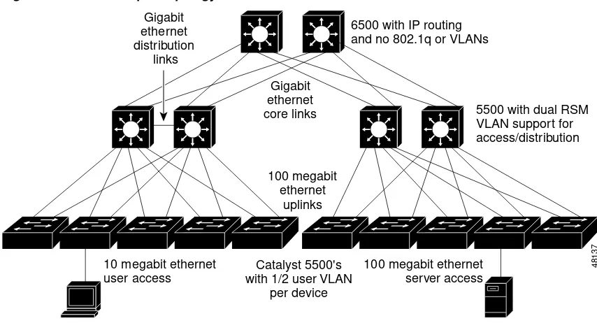
You should create a simple map, such as Figure 3-1, that describes the layers, devices, media, and port speeds. The topology map should also show the location of TFTP servers, DNS servers, DHCP servers, firewalls, and gateways.
Review the following LAN/campus topology issues:
• Available average bandwidth
• Available peak or burst bandwidth
• Resource issues that may affect performance including buffers, memory, CPU, and queue depth
• Network availability
• IP phone port availability
• Desktop/phone QoS between user and switch
• CallManager availability
• Network scalability with increased traffic, IP subnets, and features
• Backup power capability
• LAN QoS functionality
Figure 3-1 LAN/ Campus Topology
IP Addressing Plan
Review the following IP addressing plan and implementation characteristics:
• Phone IP addressing plan
• Average user IP subnet size use for the campus
• Number of core routes
• IP route summary plan
• DHCP server plan (fixed and variable addressing)
• DNS naming conventions
Potential considerations with IP addressing include:
• Route scalability with IP phones
• IP subnet space allocation for phones
• DHCP functionality with secondary addressing
• IP subnet overlap
• Duplicate IP addressing
Location of Servers and Gatew ays
Consider the location (or potential location) of servers and gateways prior to implementation and identify them in the LAN infrastructure planning phase as much as possible. Investigate other issues later to help ensure that service availability is consistent across the LAN infrastructure and for multiple sites. You should identify gateway and server network locations for the following:
• TFTP servers
• DNS servers
• DHCP servers
6500 with IP routing and no 802.1q or VLANs
• Firewalls
• NAT or PAT gateways
• CallManager location
• Gateway location
Investigate these issues after you determine the location:
• Network service availability
• Gateway support (in conjunction with IP Telephony solution)
• Available bandwidth and scalability
• Service diversity
Protocol Implementation
Investigate overall protocol uses to determine IP Telephony scalability and any potential IP Telephony availability issues or additional protocol service issues. Review the following areas for the protocol implementation analysis:
• IP routing including protocols, summarization methods, NBMA (non-broadcast media access) configurations, and routing protocol safeguards
• Spanning Tree configuration including domain sizes, root designation, uplink fast, backbone fast, and priorities in relation to default gateways
• HSRP configuration
• VTP and VLAN configuration
• IPX, DLSW, or other required protocol services including configuration and resource usage You should review the following issues in relation to protocol implementation:
• Protocol scalability
• Network availability
• Potential impact on IP Telephony performance or availability
Device Analysis
Analyze the existing network devices to help identify hardware and software issues associated with the IP Telephony deployment. Many devices may not have the desired control plane resources, interface bandwidth, QoS functionality, or power management capabilities. The following table displays device attributes that may be important:
• Device (type and product ID)
• Software version(s)
• Quantity deployed
• Modules and redundancy
• Services configured
• User media and bandwidth
• Uplink media and bandwidth
• Users per uplink and uplink load sharing/redundancy
• Number of VLANS supported
• Subnet size, devices per subnet
Netw ork Baseline
You can use a network baseline of the existing campus/LAN infrastructure for IP Telephony capacity planning. This will help determine potential voice quality issues and the impact to the existing environment. Measure the following characteristics as part of the baseline:
• Device average and peak CPU
• Device average and peak memory
• Peak backplane utilization
• Average link utilization (prefer peak hour average for capacity planning)
• Peak link utilization (prefer five minute average or smaller interval)
• Peak queue depth
• Buffer failures
• Average and peak voice call response times (before IP Telephony implementation)
Many different individuals and support organizations recommend different acceptable threshold values for these measured baseline issues. Remember that IP Telephony requires consistent performance and quality; therefore, all of the areas should be below safe recommended threshold values at all times. Use the following general guidelines on threshold issues:
• CPU—A requirement for all background processing in addition to some traffic processing requirements. Background processing includes route updates, keepalives, network management, and other critical processes for keeping the network up and stable. During stressful network times, such as route convergence or link flapping, significant CPU will be used to ensure the network remains stable and intact. Because significant CPU can be used during stress situations, a good rule of thumb is 50% peak CPU and 30% average CPU.
• Memory—Like CPU, main memory is used for background processing and traffic processing. And like CPU, significant amounts of memory can be used for a processing during link flap conditions, routing changes, and cache changes. Because significant changes can occur in memory
requirements, a good rule of thumb is 50% peak and 30% average.
• Backplane Utilization—Can be a major issue in some devices if the port speed and density is higher than the available backplane capabilities. Backplane utilization over 50% may also indicate some port queuing or dropped traffic for trunks that have less bandwidth than the sum of all downstream bandwidth.
• Link Utilization—Critical to IP Telephony deployments because of VoIP performance and jitter requirements. First, remember that SNMP thresholds for peak utilization are still mainly done for five minute intervals. A good rule of thumb is to increase bandwidth utilization 40% above the five minute value to determine a true measure of peak utilization over the five minute average. Average link utilization may also be useless over time if peak-critical traffic occurs during a shorter interval of one hour. The telecom community thinks in terms of “busy hour” traffic. If you perform capacity planning using this busy hour utilization, then data network managers can consistently meet both voice and data requirements.
bandwidth is available towards the core to help minimize or eliminate significant or critical congestion problems. Therefore, care should be taken for all core network links that have peak utilization in excess of 50% and average utilization above 30%. VoIP will likely work if it is higher, but there will be more opportunity for potential intermittent bandwidth problems that will first affect the critical voice traffic.
• Queue Depth—Indicates link congestion. Any transmit queues that experience any volume at all indicate that traffic is waiting. This directly impacts voice jitter and delay and indicates that link utilization is exceeding a peak recommended value.
• Buffer Failures—Indicates a temporary inability to perform control processing in the device and should be investigated in terms of overall network health. Some buffer failure issues could impact VoIP quality and should be investigated.
Note Cisco can provide a network baseline called the IP Telephony readiness Net Audit (http://www.cisco.com/warp/public/cc/serv/mkt/sup/ent/avvid/nadit_ds.htm).
W AN Environment
We recommend a WAN infrastructure analysis for multiple-site WANs with distributed call processing or multi-site IP WANs with centralized call processing. The WAN analysis determines infrastructure and bandwidth issues that will affect IP Telephony quality and reliability. You should collect the following information for the WAN environment analysis:
• WAN topology
• Location of gateways and servers
• WAN protocols
• Existing QoS requirements
• Device Analysis including software versions, modules, ports, speeds and interfaces
• WAN baseline
Note Review “LAN/Campus Environment” for information on location of gateways, IP addressing plan, and protocol implementation. We recommend some LAN analysis for all WAN sites supporting IP Telephony.
W AN Topology
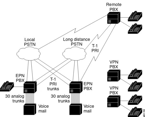
You normally build WAN topology infrastructures using a hub and spoke model, meshed multi-site model, or a combination of both. You should create a WAN diagram showing potential IP Telephony sites, WAN devices, remote LAN devices, interface types, and bandwidth. The map should show the location of DNS servers, DHCP servers, firewalls, gateways, and potential CallManager locations. See
Figure 3-2 for a sample WAN topology. Review the following WAN topology issues:
• WAN availability, including bandwidth redundancy and resiliency
Note The Cisco IP Telephony Network Design Guide currently recommends a hub and spoke topology until call admission control using RSVP (Resource Reservation Protocol) is completely available. This document can be found at the following location:
http://www.cisco.com/univercd/cc/td/doc/product/voice/ip_tele/index.htm.
• WAN scalability with increased traffic, IP subnets, and features
• Bandwidth and WAN service expectations
• Existing QoS requirements (see the “Designing for LAN/WAN QoS” section on page 4-2 for more information.)
Figure 3-2 WAN Infrastructure
Location of Servers and Gatew ays
Consider the location (or potential location) of servers and gateways in the WAN prior to implementation and identify them in the WAN infrastructure planning phase as much as possible. Identify the following gateway and server network locations:
• TFTP servers
• DNS servers
• DHCP servers
• Firewalls
• NAT or PAT gateways
• CallManager location
• Gateway location
You should investigate the following issues after you determine the location:
• WAN outage impact and service diversity
• Gateway support (in conjunction with IP Telephony)
• Available bandwidth and scalability
W AN Protocols
You should investigate WAN protocols for issues that may impact IP Telephony quality or issues that may be affected by additional voice services. In many cases, the WAN may require further optimization to better support IP Telephony traffic. NBMA (non-broadcast multiaccess) environments may also be susceptible to protocol issues and overall reliability that can affect voice quality. Investigate the following specific issues:
• WAN IP protocol implementation and protocol overhead
• IP multicast implementation
• Carrier Service subscription rates including port speed, committed information rates, and expected performance
• NBMA protocol issues affecting voice quality and performance
• Other protocol overhead, including IPX and SNA
Analyze the following areas after investigating WAN protocol issues:
• Protocol optimization
• WAN scalability with increased traffic
• Expected network convergence with redundant topologies
• Carrier reliability and quality expectations with WAN protocols
Existing QoS Requirements
You should evaluate existing WAN QoS requirements to determine compatibility with Voice QoS requirements. You should identify applications and performance requirements, including application performance, burst requirements, and batch requirements. Investigate the following areas:
• Existing WAN QoS configurations
• Critical application requirements, including raw performance, burst bandwidth, and batch bandwidth
• WAN call admission control
Device Analysis
An analysis of existing network devices in the network helps identify hardware and software issues associated with the IP Telephony deployment. Software versions are important to determine QoS requirement compatibility. You can also use this information to create a network reliability path analysis to help determine potential network availability. The following table displays device attributes that may be important:
• WAN Devices
• Software Version(s)
• Remote LAN Devices
• Software Version(s)
• Quantity Deployed
• Modules and Redundancy
• WAN Media/Bandwidth
• LAN Media/Bandwidth
• Switched vs. Shared Media
• User and IP Addressing per WAN Site
W AN Baseline
You can use a WAN baseline of the existing WAN and WAN site infrastructure for IP Telephony capacity planning. This will help determine potential voice quality issues and the impact to the existing
environment. Measure the following characteristics as part of the baseline:
• Device average and peak CPU
• Device average and peak memory
• Average link utilization (prefer peak hour average for capacity planning)
• Peak link utilization (prefer five minute average or smaller interval)
• Peak queue depth
• Buffer failures
• Average and peak voice call response times (before IP Telephony implementation) See the “Network Baseline” section on page 3-6 for specific guidelines for measuring these characteristics.
Evaluating and Documenting the Existing Telecom
Infrastructure
You need to evaluate the existing Telecom infrastructure to help determine IP Telephony requirements. Perform this analysis for all sites implementing VoIP technology to determine the appropriate
deployment model. IP Telephony supports the following deployment models:
• Single-site deployment
• Multiple single-site deployments interconnected via PSTN
• Distributed IP Telephony sites with centralized call processing
• Distributed IP Telephony sites with distributed call processing
The Telecom infrastructure analysis examines the products, services, and features used in the existing telecom environment including:
• PBX systems and locations
• Voice mail systems and locations
• Key systems
• PBX inter-connectivity
• Phone requirements
• PSTN trunking
• Voice mail trunking
The analysis will then help determine the IP Telephony design criteria. You should examine the following issues:
• Existing PBX topology, including voice mail servers
• PBX and Key Systems
• Voice mail system
• Voice trunking
• Phones per site and phone features
• Existing dial plan
• Fax requirements
Examining the Existing Telecom Topology
The existing Telecom topology includes the location and internetworking connectivity for PBX systems, key systems, and voice mail servers. The topology should include the location of these devices and the trunks between systems used for connectivity. Trunking may include site-to-site trunks, PSTN trunks, and voice mail trunks. This section reviews the following existing Telecom topology issues:
• PBX system connectivity overview
• Trunking overview
Examining PBX and Key Systems
You need PBX and key system information to help understand current voice features and functionality. The following information will help determine required features and PBX-to-IP Telephony connectivity requirements.
• PBX or KSU vendor and model
• Quantity and locations of PBX/KSU systems
• Release of software running on PBX or KSU
• Quantity and location of PBXs with which IP Telephony may interface
• Hardware models and revisions of installed cards
• Software features currently deployed, which may include call setup, conferencing, call transfer, call hold, call park, calling line identity, and calling party name
• Number of existing analog connections for each PBX or KSU and three expected to remain following deployment
• Number of existing digital connections for each PBX/KSU and those that will remain
• Number and capacity of ISDN trunks connected to each PBX
Examining Voice M ail Systems
You will need the following information to determine IP Telephony compatibility and feature capabilities:
• Voice mail system models and vendor
• Quantity and locations of voice mail systems
• Hardware model and revision cards of voice mail systems
• List of software features currently deployed with voice mail system
• Does the voice mail system have an SMDI interface?
• How is the voice mail system connected to the PBX?
• Is the message waiting indicator integrated into the voice mail solution?
Examining Voice Trunking
You may also use the following tables for planning and configuring the gateway trunks. In some cases, you may move these trunk Demarc locations to co-exist with IP Telephony equipment. In addition, you should document support responsibility for WAN carrier services for use in physical design documents.
Table 3-1 Trunking M atrix
Digital or Analog Tw o-w ay Calling DID Trunks DOD Trunks
Voice Mail Trunks
Local PSTN Trunks
LD PSTN Trunks
Trunks to Site X
Trunks to Site Y
Table 3-2 PBX WAN Trunk Information
Table 3-3 PBX WAN Trunk Cable Infrastructure Information
Note When ordering your DID, get a block of telephone (DID) numbers equal to or greater than the number of devices (phones, virtual phones, and H.323 devices such as NetMeeting) that will be connected to the network.
4.
5.
6.
7.
8.
9.
10.
Table 3-3 PBX WAN Trunk Cable Infrastructure Information
Local Site A Name:
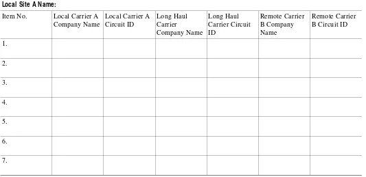
Table 3-4 PBX WAN Carrier and Circuit Information
Local Site A Name:
Item No. Local Carrier A Company Name
Local Carrier A Circuit ID
Long Haul Carrier
Company Name
Long Haul Carrier Circuit ID
Remote Carrier B Company Name
Remote Carrier B Circuit ID
1.
2.
3.
4.
5.
6.
ISDN PRI is a common PBX WAN trunk type. The following parameters are typically used when provisioning a T-1 or E-1 PRI span:
• Interface: ISDN Primary Rate Interface (PRI)
• Frame Format: Extended Super Frame (ESF)
• Line Encoding: B8ZS
• Number of B-Channels: 23 and 30 for Euro
• D-Channel: on channel 24th or Euro PRI it is the 16th
• Line Use: Voice
ISDN PRI provisioning also requires a switch type to be configured for Layer 3 protocols. There are four families of switch type protocols for PRI provisioning:
• AT&T, 4ESS, 5ESS, NII Called NI2 (National Protocols)
• DMS100 and DMS 250 (National Protocols)
• EUROPEAN PRI
• Custom 5ESS IntecomE
Common switch types and Layer 3 protocols include the following switch types for well-known PBX systems:
• Nortel (Meridian): 5ESS Custom NOTE: Gateway must be set to NETWORK
• Lucent (Definity): 4ESS or 5ESS
• MCI: DMS 250
• SPRINT: DMS 100 or DMS 250
• AT&T: 4ESS
• Madge (Teleos) BOX: 5ESS Custom
• Intecom: 5ESS Custom
Common switch types and Layer 3 protocols for IXCs and inter-exchange carriers include the following:
• AT&T: 4ESS
• MCI or SPRINT: DMS250
• When connecting to a local CO switch use the following:
• 5ESS (5E8 or 5E9)
• DMS 100
• NII 8.
9.
10.
Table 3-4 PBX WAN Carrier and Circuit Information
• Hunt Sequence: Float, Flex, or Fixed
• Out-pulse of digits: 4 is standard, but can be from 1 to 23 digits
Phones per Site and Phone Features
You will need the number of currently supported phones to properly size the CallManager platforms. You should identify phones that will convert to VoIP and potentially some analog phones for emergency and fax backup.You should also know the required phone features, which may include the following:
• Speaker capability
• Mute
• Call hold
• Call park
• Call transfer
• Calling line identity
• Calling party name
• Multi-party conferencing
Examining the Existing Dial Plan
Examine the existing dial plan architecture to understand the required call routing, abbreviated dialing, and route-group features for IP telephony migration. Call routing is used for PSTN or offnet access. Features associated with call routing include:
• Redundant or back-up paths (transparent to the user)
• Emergency dialing call patterns
• Automatic call distribution
• Call blocking where individual groups or numbers have limited offnet access.
Automatic call distribution allows many agents to answer calls from one published number. Call blocking is used to limit access to certain numbers such as 900 toll numbers or long distance PSTN access from building lobby phones. Abbreviated dialing is used to reduce the number of digits required for extension calls. In many cases, local extension dialing has been reduced to 4-digit numbers. Questions for the IP Telephony deployment include:
• Will the organization use existing or distributed dial plans among multiple sites?
• Are there number ranges to be reserved for PBXs? If so, what are they?
You should also consider the following issues:
• What is the local PSTN access dial plan?
• Besides local PSTN access, is there a cellular network to be included in the deployment?
• What access code is used at each site for routing local off-net calls to PSTN?
To answer these questions, you can list all local PSTN calling patterns for each site and the route option for each calling pattern (route this pattern or block this pattern) in the following table format:
Note There could be multiple dial patterns for local PSTN access for non-North America dial plan areas.
Table 3-5, Part 1 Dial Plan Details
Site Name
IP Phone Dial Plan (indicate how many digits for on-net
dialing) PBX Dial Plan Analog Dial Plan
PBX Dial Plan (indicate how many digits for dialing)
PBX PBX Gateway Analog Phone Dial Plan
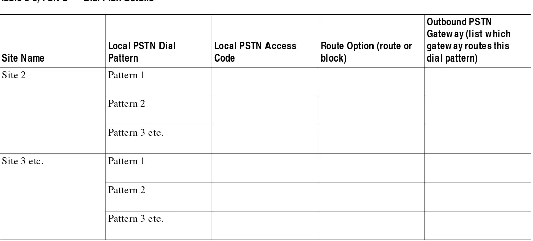
Table 3-5, Part 2 Dial Plan Details
Site Name
Local PSTN Dial Pattern
Local PSTN Access Code
Route Option (route or block)
Outbound PSTN Gatew ay (list w hich gatew ay routes this dial pattern)
Site 1 Pattern 1
Pattern 2
You should also consider the following issues:
• What is the Long Distance PSTN Access Dial Plan?
• Besides PSTN, is there a cellular network to be included in the deployment?
• Is it required to deploy long distance PSTN call toll bypass within the IP Telephony deployment sites (i.e., route long distance PSTN calls to the PSTN gateway in the destination city so that the call is via VOIP instead of PSTN)? Or is it required just to route all long distance off-net calls to PSTN? To answer these questions, you can list all access codes, long distance calling pattern (including cellular net, if any, and both domestic and international calling patterns) for each city and the route option for each calling pattern (route this pattern or block this pattern) in the following table format:
Site 2 Pattern 1
Pattern 2
Pattern 3 etc.
Site 3 etc. Pattern 1
Pattern 2
Pattern 3 etc.
Table 3-5, Part 2 Dial Plan Details
Site Name
Local PSTN Dial Pattern
Local PSTN Access Code
Route Option (route or block)
Outbound PSTN Gatew ay (list w hich gatew ay routes this dial pattern)
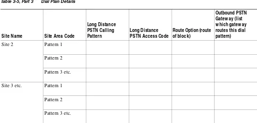
Table 3-5, Part 3 Dial Plan Details
Site Name Site Area Code
You should also list all special call routing and call distribution requirements here, such as:
• E-911 calling
• 900 call blocking
• ACD (Automatic Call Distribution)
Inbound Dial Plan
For each site, list the incoming called numbers for PSTN users to reach IP phone users. Site 2 Pattern 1
Pattern 2
Pattern 3 etc.
Site 3 etc. Pattern 1
Pattern 2
Pattern 3 etc.
Table 3-5, Part 3 Dial Plan Details
Site Name Site Area Code
Long Distance PSTN Calling Pattern
Long Distance PSTN Access Code
Route Option (route of block)
Outbound PSTN Gatew ay (list w hich gatew ay routes this dial pattern)
Table 3-6 Inbound Dial Plan
Site Name
DID or Tw o-stage Dialing (specify IVR, auto-attendant)
Inbound PSTN Gatew ay (w hich PSTN gatew ay routes incoming calls)
DID Number Range or IVR/AA M ain Incoming Called Number
Site 1
Site 2
Site 3
Fax Requirements
CallManager versions 3.0.1 or later support fax-relay and modem pass-through on certain gateways. You must then define fax-relay requirements and modem pass-through requirements by identifying fax machines, locations, and fax numbers. You may potentially need to identify modems for a modem pass-through solution. You can use the following table to identify fax machines, modems, and information required to design the IP Telephony-based VoIP solution in this area:
Evaluating and Documenting the Existing Pow er/Cabling
Infrastructure
Another aspect of successful IP Telephony deployment and a high availability voice solution is power and cabling infrastructure. Traditional voice environments typically have well-planned power and cabling systems with UPS power backup and PBX-powered phones. This solution helps to create a more highly available voice implementation. To provide a similar high availability solution, the organization may need to better plan for a highly available cabling and power infrastructure for data equipment. Without UPS power, organizations can expect to have approximately 1.66 hours of non-availability due to power alone. Refer to the following APC website for detailed information:
http://www.apcc.com/go/machine/cisco/.
Cabling infrastructure issues can also cause availability problems due to poor installation practices, patch cord management, non-hierarchically structured installations, and non-standards-based
installations. To ensure that you meet the availability requirement, you should understand your cabling infrastructures and plan for potential upgrades.
The first step is to examine the existing cabling and power infrastructure to ensure that power and cabling infrastructures are capable of handling IP Telephony requirements. Refer to the following locations for more information on power:
• Cisco IP Telephony Voice and Video Solutions
http://www.cisco.com/warp/public/779/largeent/avvid/solutions/powerpro.html
• APC home page
http://www.apcc.com
Table 3-7 Fax Details
Device Location Current Number PBX or Analog
Fax
Fax
Modem
Basic questions that may help determine the current infrastructure readiness include:
• Does the building wiring conform to EIA/TIA-568A? Technical Services Bulletin 40 (TSB-40) defines the installation of category 5 wiring systems. TSB-67 defines the testing criteria to ensure compliance. If the wiring does not conform, contact your wiring contractor for testing and potential upgrade.
• Does your organization comply with National Electric code for powering and grounding sensitive equipment? If not or you are unsure, contact APCC for a power audit to determine the compliance and availability characteristics of your environment.
• Does your organization comply with the more rigorous IEEE 1100-1992 standard for recommended practices of grounding and powering sensitive equipment? If not or you are unsure, contact APCC for a power audit to determine the compliance and availability characteristics of your environment.
• Does the organization have standards for data center and wiring closet power that include circuit distribution, available power validation, redundant power supply circuit diversity, and circuit identification?
• Does the organization use UPS and/or generator power in the data center, wiring closet, phone systems, and internetworking devices?
• Does the organization have processes to SNMP manage or periodically validate and test backup power?
• Does your business experience frequent lightening strikes? Are there other potential natural disasters?
• Is the wiring to your building above ground?
• Is the wiring in your building above ground?
• Will the organization determine power draw, plug-type, and heat output for IP Telephony-sensitive equipment before installation to ensure adequate power, a smooth installation, and adequate power backup?
Refer to the following power sizing guide for more information:
http://www.cisco.com/warp/public/779/largeent/avvid/solutions/powerpro.html.
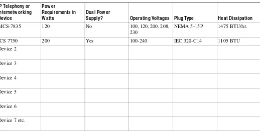
Data Center Pow er Requirements
CallManagers and gateway devices should be used in data center environments. Evaluate the existing data center in terms of available main power, UPS power, power plug compatibility, and heat dissipation for the potential IP Telephony equipment. You can use the following table to help determine overall IP Telephony power requirements and data center power and cooling requirements. You can find power draw in Watts, operating voltages, and plug type at the following APC website:
http://www.apcc.com/template/size/apc/cisco_int/index.cfm.
You can locate heat dissipation, line voltage, and other environmental information in the Cisco IP Telephony data sheets. These documents can be found at the following location:
W iring Closet Pow er
Wiring closet power may require careful planning due to the use of Cisco Inline Power™ and the addition of wiring closet UPS systems. This will help ensure high availability to end phones. Inline Power requires space planning for powered patch panels. The organization should complete wiring closet worksheets, similar to the data center worksheet, to define power, UPS, and cooling requirements.
Table 3-8 Power Requirements
IP Telephony or Internetw orking Device
Pow er
Requirements in W atts
Dual Pow er
Supply? Operating Voltages Plug Type Heat Dissipation
MCS-7835 120 No 100, 120, 200, 208, 230
NEMA 5-15P 1475 BTU/hr.
ICS 7750 200 Yes 100-240 IEC 320-C14 1105 BTU Device 2
Device 3
Device 4
Device 5
Device 6
Device 7 etc.
Table 3-9 Wiring Closet Pow er
IP Telephony or Internetw orking Device
Pow er
Requirements in W atts
Dual Pow er
Supply? Operating Voltages Plug Type Heat Dissipation
MCS-7835 120 No 100, 120, 200, 208, 230
NEMA 5-15P 1475 BTU/hr.
ICS 7750 200 Yes 100-240 IEC 320-C14 1105 BTU Inline Patch Panel 175 No 100, 120, 200, 208,
230
NEMA 5-15P
Device 3
Device 4
IP Telephony Availability Requirements
You should design the IP Telephony network, infrastructure, and support services with targeted availability requirements. Availability planning is useful for several reasons:
• You can use availability as an overall SLA for the voice/data service.
• You can use availability modeling or measurement to determine the best availability level based on the cost of downtime, potential analysis, and a simple ROI (return on investment) calculation.
• You can use availability measurement in a quality availability improvement process to improve the level of service.
Cisco views availability as a combination of six major factors:
• Hardware availability
• Software reliability
• Link/Carrier availability
• Power/Environment availability
• Network Design reliability
• User error and network support processes
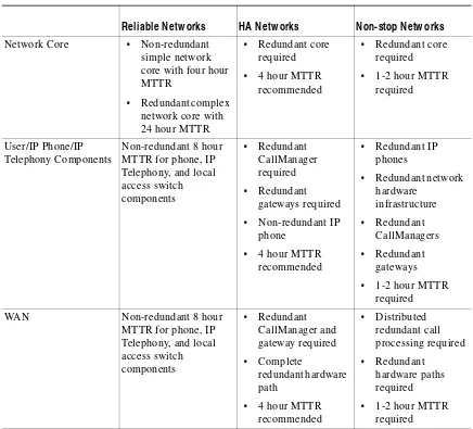
Each of these issues may impact different parts of the network in different ways. It is therefore useful to define availability requirements and models for different areas of the network. These may typically be the LAN, WAN, data center, or network core. Cisco currently has general availability classifications that correspond to the business requirements and cost of downtime experienced by the organization. These general classifications are:
• Reliable networks—Availability goal is approximately 99.5% over time (education and government).
• High availability networks—Availability goal is approximately 99.99% over time (high tech, manufacturing, and service).
• Non-stop networks—Availability goal is typically 99.999% and higher over time (financial or some medical environments).
Reliability block diagrams help an organization model availability requirements. Since each availability factor can occur independently of others, the factors are multiplied together to achieve a final result. The result is that if one area is weak, overall availability will be affected more severely. See the following example:
Device 6
Device 7 etc.
Table 3-9 Wiring Closet Pow er
IP Telephony or Internetw orking Device
Pow er
Requirements in W atts
Dual Pow er
For instance, hardware reliability typically uses MTBF (mean time between failure) analysis combined with MTTR (mean time to repair) to better model theoretical hardware reliability. In other cases, precise modeling is not possible, but general overall characteristics of the “best practices” have been identified. The following sections provide more detail regarding the best practices within each of the three availability types for each availability factor.
Hardw are Reliability
You should measure the reliability of hardware in the network given the network topology, amount of redundancy, and expect time required to repair broken hardware. You can perform hardware reliability calculations using the MTBF of each device (and device modules) and the MTTR for hardware replacement. Hardware reliability for the IP Telephony solution should also include the path between the IP phone and the CallManager, as well as the path between the IP phone and the called party.
Your Cisco account team can provide precise hardware modeling using the expected MTTR. The account team will then contact manufacturing quality to determine the MTBF for each device and module so that they can perform a path analysis on a case-by-case basis. MTBF information is based on the BellCore standard for component quality. BellCore has identified the expected lifetime of more than 500,000 components that are used to manufacture Cisco modules and chassis.
The MTTR is critical in overall hardware reliability. Organizations relying on standard Cisco SmartNET hardware replacement can expect an average of 24-48 hours for hardware replacement, which will lower the availability of the overall solution.
The following table will help characterize the availability of the IP Telephony solution given different areas of the network, replacement times, and the amount of hardware redundancy:
Table 3-10 Reliability M atrix
Netw ork Area
Hardw are Reliability
Softw are Reliability
Link/Carrier Reliability
Pow er Environment
Netw ork Design
User-error Process
Overall Estimated Ability
Core HA HA HA HA non-stop HA HA
LAN HA HA HA HA non-stop HA HA
Softw are Reliability
Organizations cannot easily control software reliability since software quality is primarily the responsibility of the vendor. Cisco strives to release only high quality software at or above 99.999% reliability. However, in many cases, early deployment software and early release software falls short of this goal due to unexpected and untested traffic patterns or load related issues.
Cisco IOS also has several classifications of software that correspond to the expected reliability. These include GD (general deployment), LD ( limited deployment), and ED (early deployment). In addition, the IOS may have untested interim releases and experimental releases. GD code is considered highly reliable and generally has a proven track record of 99.999% availability.
Some organizational processes contribute to higher software reliability and availability within the organization. The first is software version control. This practice involves maintaining only a few versions of software on the network that have proven track records and that have been tested or piloted within the network to prove reliability.
Table 3-11 Hardware Reliability M atrix
Reliable Netw orks HA Netw orks Non-stop Netw orks
Network Core • Non-redundant simple network core with four hour MTTR
Another best practice is software testing. Software testing includes feature testing and “what-if” testing to determine the software impact to the existing environment. Cisco offers a testing service called Network Verification Services (NVS) that can help organizations better test their software, hardware, and network designs. Refer to the Network Verification Service Option document for more information on the NVS service. This document can be found at the following location:
http://www.cisco.com/warp/public/cc/serv/mkt/sup/ent/nsa/welcome/nsan_ov.htm.
NVS is currently only available to ANS or BES customers. Other testing tools and modeling tools are also available. These tools can capture packets, generate traffic, and even insert delay. It is especially important to create a lab where you can adequately test products and features prior to deployment. One popular test device is the SmarBits traffic generator. Refer to the following Spirent Communications SmartBits website for more information:
http://www.netcomsystems.com/.
You will also need processes to manage overall network consistency including topology, software versions, configuration, and features. Consistency within the software configuration can always help contribute to availability as less code is exercised and fewer opportunities for problems can occur.
Table 3-12 helps to identify factors involved in overall software reliability at the various levels.
Link/Carrier Availability
The following factors can contribute to link/carrier availability:
• Campus fiber installation quality, redundancy, and geophysical diversity
• Building riser installation quality, redundancy, and diversity
• Cable testing and validation
• Patch cord management and cable labeling
• Cabling installation age
• Building entrance facilities and diversity
• Local loop carrier resiliency, redundancy, and diversity
• Long distance carrier resiliency, redundancy, and diversity
• Bandwidth redundancy
Table 3-12 Software Reliability M atrix
Reliable Netw orks High Availability Netw orks Non-stop Netw orks
• General Release software only
• Software version control recommended
• Lab testing or solution pilot recommended
• Configuration consistency required
• General Release software only
• Software version control required
• Testing including what-if analysis, feature testing and load testing required
• Configuration consistency required
• General Deployment or older proven software required
• Software version control required
• Testing including what-if analysis, feature testing, and load testing required
Many of these factors are controllable within an organization with the possible exception of local loop and long distance resiliency, redundancy, and diversity. Many carrier infrastructures, especially in third-world countries and parts of Asia, have limited resiliency and almost no redundancy or diversity. Infrastructure repairs can also take days instead of hours or minutes. In developed countries,
organizations often have the opportunity for path diversity, multiple carriers, and higher overall availability and yet failures still can occur that affect redundant configurations. This is a because the entire circuit path is not diverse and redundant. In many cases, complete redundancy and diversity is still not an option. The organization should strive to understand cable paths and single points of failure within the local loop system and carrier infrastructure to help understand all the potential availability issues. The following table will help characterize link/carrier infrastructure requirements at the three
availability levels:
Table 3-13 Link/ Carrier M atrix
Reliable Netw orks High Availability Netw orks Non-stop Netw orks
• Patch cord management and cable labeling recommended
• Cabling infrastructure younger than 10 years recommended
• Local loop resilient infrastructure required
• Long distance resilient infrastructure required
• Copper Cabling infrastructure follows EIA-TIA 568 standard and is tested in conformance with TSB-67
• Fiber cabling tested to ensure DB loss within spec for required media
technology
• Redundant riser and campus cabling infrastructure recommended
• Patch cord management and cable labeling required to ensure cable traceability and to ease hardware
replacement (if necessary)
• Campus core link diversity recommended
• WAN long distance carrier redundancy and diversity required
• Significant Local Loop resiliency and redundancy and bandwidth redundancy recommended
• Copper Cabling infrastructure follows EIA-TIA 568 standard and is tested in conformance with TSB-67
• Fiber cabling tested to ensure DB loss within spec for required media
technology
• Redundant riser and campus cabling infrastructure required
• Multiple building entrance facilities required
• Patch cord management and cable labeling required to ensure cable traceability and to ease hardware
replacement (if necessary)
• Campus core link diversity required
• WAN long distance carrier redundancy and diversity required
• Local loop redundancy and geophysical diversity required
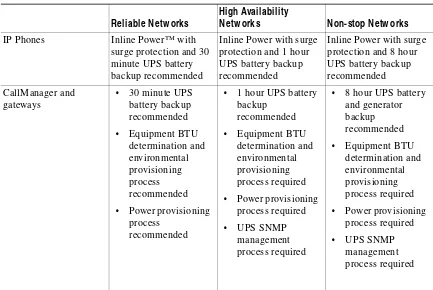
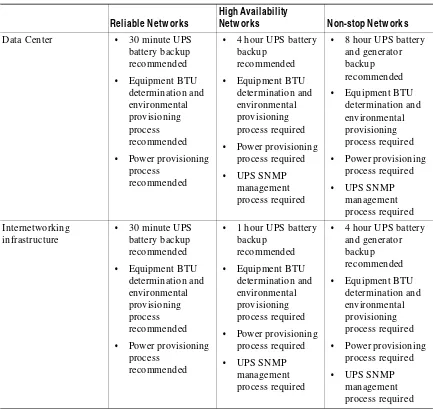
Pow er/Environment
The following factors affect power and environment-related availability:
• Power backup systems
• Network management systems used to monitor UPS and environmental conditions
• IP Telephony equipment
• Environmental conditions
• The processes used to provision equipment and manage power The following factors contribute to power/environment availability:
• Environmental cooling and temperature control
• Equipment BTU and determination
• Environmental conditioning provisioning processes
• Power provisioning process to ensure circuit wattage availability and circuit redundancy for redundant equipment and power supplies
• Equipment surge protection
• UPS battery backup systems
• Generator systems
• SNMP or other remote management processes for UPS systems
• Geographic location of equipment where lightening strikes, floods, earthquakes, severe weather, tornados, or snow/ice/hail storms can affect power reliability
• Power cabling above ground
• Construction near or within equipment facility
• Power cabling infrastructure conformance to NEC and IEEE wiring standards for safety and ground control
Table 3-14 Power M atrix
Reliable Netw orks
High Availability
Netw orks Non-stop Netw orks
IP Phones Inline Power™ with surge protection and 30 minute UPS battery backup recommended
Inline Power with surge protection and 1 hour UPS battery backup recommended
Netw ork Design
Factors that contribute to network design availability and reliability include:
• Modular and hierarchical logical design
• Hierarchical IP routing infrastructure supporting IP route summarization
• Consistent hardware, software, and device configuration
• High availability, high performance media and devices
• High availability convergence capabilities at level II and level III
• QoS functionality in the LAN/WAN supporting low voice delay and jitter
• Design testing
• Vendor approval
• Capacity and Performance management processes Data Center • 30 minute UPS
battery backup
Table 3-14 Power M atrix
Reliable Netw orks
High Availability
• Network change management that promotes network consistency and change validation for higher risk change
• Minimize or eliminate spanning tree with IP routing
The following table provides basic network design characteristics that you need at the three defined availability levels:
Table 3-15 Design Characteristics for Availability Levels
Reliable Netw orks High Availability Netw orks Non-stop Netw orks
• Modular and hierarchical logical network design required
• Consistent hardware, software, and configuration recommended
• Hierarchical IP routing infrastructure supporting IP summarization
recommended
• High performance media and devices recommended
• Fast converging spanning tree parameters
recommended
• HSRP gateway redundancy features recommended
• Fast converging IP routing protocol EIGRP or OSPF recommended
• Modular and hierarchical logical network design required
• Consistent hardware, software, and configuration required
• Hierarchical IP routing infrastructure supporting IP summarization required
• High performance media and devices required
• QoS in LAN at level II/III required
• QoS in WAN with call admission control required
• Fast converging Spanning Tree parameters required
• HSRP gateway redundancy features required
• Fast converging IP routing protocol EIGRP or OSPF required
• Change management validation and vendor approval recommended
• Capacity and performance management processes for baselining, exception management, and what-if analysis recommended
• Modular and hierarchical logical network design required
• Consistent hardware, software, and configuration required
• Hierarchical IP routing infrastructure supporting IP summarization required
• High performance media and devices required
• QoS in LAN at level II/III required
• QoS in WAN with Call admission control required
• Fast converging Spanning Tree parameters required
• HSRP gateway redundancy features required
• Fast converging IP routing protocol EIGRP or OSPF required
• Change management validation and vendor approval required