Steel Design Guide Series
Steel and Composite Beams with
Steel Design Guide Series
Steel and
Composite Beams
with Web Openings
Design of Steel and Composite Beams with Web Openings
David Darwin
Professor of Civil Engineering
University of Kansas
Copyright1990
by
American Institute of Steel Construction, Inc.
All rights reserved. This book or any part thereof must not be reproduced in any form without the
written permission of the publisher.
The information presented in this publication has been prepared in accordance with rec-ognized engineering principles and is for general information only. While it is believed to be accurate, this information should not be used or relied upon for any specific appli-cation without competent professional examination and verifiappli-cation of its accuracy, suitablility, and applicability by a licensed professional engineer, designer, or architect. The publication of the material contained herein is not intended as a representation or warranty on the part of the American Institute of Steel Construction or of any other person named herein, that this information is suitable for any general or particular use or of freedom from infringement of any patent or patents. Anyone making use of this information assumes all liability arising from such use.
Caution must be exercised when relying upon other specifications and codes developed by other bodies and incorporated by reference herein since such material may be mod-ified or amended from time to time subsequent to the printing of this edition. The Institute bears no responsibility for such material other than to refer to it and incorporate it by reference at the time of the initial publication of this edition.
Printed in the United States of America
Second Printing: September 1991
TABLE OF CONTENTS
INTRODUCTION . . . 1
DEFINITIONS AND NOTATION . . . 3
2.1 Definitions . . . 3
2.2 N o t a t i o n . . . 3
DESIGN OF MEMBERS WITH WEB OPENINGS 7 3.1 G e n e r a l . . . 7
3.2 Load and Resistance Factors . . . 7
3.3 Overview of Design Procedures . . . 7
3.4 Moment-Shear Interaction . . . 8
3.5 Equations for Maximum Moment Capacity, Mm . . . 8
3.6 Equations for Maximum Shear Capacity, Vm . . . 10
3.7 Guidelines for Proportioning and Detailing Beams with Web O p e n i n g s . . . 12
3.8 Allowable Stress Design . . . 16
DESIGN SUMMARIES AND EXAMPLE P R O B L E M S. . . 17
4.1 General.. . . 17
4.2 Example 1: Steel Beam with Unreinforced Opening . . . 22
4.3 Example 1A: Steel Beam with Unreinforced Opening—ASD Approach . . . 23
4.4 Example 2: Steel Beam with Reinforced O p e n i n g . . . 24
4.5 Example 3: Composite Beam with Unreinforced Opening . . . 27
4.6 Example 4: Composite Girder with Unreinforced and Reinforced Openings . . . 30
BACKGROUND AND COMMENTARY . . . 37
5.1 G e n e r a l . . . 37
5.2 Behavior of Members with Web Openings . . . 37
5.3 Design of Members with Web Openings . . . 40
5.4 Moment-Shear Interaction . . . 41
5.5 Equations for Maximum Moment Capacity . . . . 42
5.6 Equations for Maximum Shear Capacity . . . 44
5.7 Guidelines for Proportioning and Detailing Beams with Web Openings . . . 48
5.8 Allowable Stress Design . . . 50
D E F L E C T I O N S. . . 51
6.1 General. . . 51
6.2 Design Approaches . . . 51
6.3 Approximate Procedure . . . 51
6.4 Improved Procedure . . . 52
6.5 Matrix A n a l y s i s . . . 53
R E F E R E N C E S. . . 55
ADDITIONAL BIBLIOGRAPHY . . . 57
APPENDIX A . . . 59
PREFACE
This booklet was prepared under the direction of the Com-mittee on Research of the American Institute of Steel Con-struction, Inc. as part of a series of publications on special topics related to fabricated structural steel. Its purpose is to serve as a supplemental reference to the AISC Manual of Steel Construction to assist practicing engineers engaged in building design.
The design guidelines suggested by the author that are out-side the scope of the AISC Specifications or Code do not
represent an official position of the Institute and are not
in-tended to exclude other design methods and procedures. It is recognized that the design of structures is within the scope of expertise of a competent licensed structural engineer, ar-chitect or other licensed professional for the application of principles to a particular structure.
The sponsorship of this publication by the American Iron and Steel Institute is gratefully acknowledged.
The information presented in this publication has been prepared in accordance with recognized engineer-ing principles and is for general information only. While it is believed to be accurate, this information should not be used or relied upon for any specific application without competent professional examination and verifi-cation of its accuracy, suitability, and applicability by a licensed professional engineer, designer or archi-tect. The publication of the material contained herein is not intended as a representation or warranty on
the part of the American Institute of Steel Construction, Inc. or the American Iron and Steel Institute, or of any other person named herein, that this information is suitable for any general or particular use or of
Chapter 1
INTRODUCTION
Height limitations are often imposed on multistory buildings based on zoning regulations, economic requirements and es-thetic considerations, including the need to match the floor heights of existing buildings. The ability to meet these restric-tions is an important consideration in the selection of a fram-ing system and is especially important when the framfram-ing sys-tem is structural steel. Web openings can be used to pass utilities through beams and, thus, help minimize story height. A decrease in building height reduces both the exterior sur-face and the interior volume of a building, which lowers oper-ational and maintenance costs, as well as construction costs. On the negative side, web openings can significantly reduce the shear and bending capacity of steel or composite beams. Web openings have been used for many years in structural steel beams, predating the development of straightforward design procedures, because of necessity and/or economic ad-vantage. Openings were often reinforced, and composite
beams were often treated as noncomposite members at web
openings. Reinforcement schemes included the use of both horizontal and vertical bars, or bars completely around the periphery of the opening. As design procedures were devel-oped, unreinforced and reinforced openings were often ap-proached as distinct problems, as were composite and non-composite members.
In recent years, a great deal of progress has been made in the design of both steel and composite beams with web
openings. Much of the work is summarized in state-of-the-art reports (Darwin 1985, 1988 & Redwood 1983). Among the benefits of this progress has been the realization that the behavior of steel and composite beams is quite similar at web openings. It has also become clear that a single design approach can be used for both unreinforced and reinforced openings. If reinforcement is needed, horizontal bars above and below the opening are fully effective. Vertical bars or bars around the opening periphery are neither needed nor cost effective.
This guide presents a unified approach to the design of structural steel members with web openings. The approach is based on strength criteria rather than allowable stresses, because at working loads, locally high stresses around web openings have little connection with a member's deflection or strength.
Chapter 2
DEFINITIONS AND NOTATION
2.1 DEFINITIONS
The following terms apply to members with web openings.
bottom tee—region of a beam below an opening. bridging—separation of the concrete slab from the steel
sec-tion in composite beams. The separasec-tion occurs over an
opening between the low moment end of the opening and a point outside the opening past the high moment end of the opening.
high moment end—the edge of an opening subjected to the
greater primary bending moment. The secondary and
pri-mary bending moments act in the same direction.
low moment end—the edge of an opening subjected to the lower primary bending moment. The secondary and pri-mary bending moments act in opposite directions.
opening parameter—quantity used to limit opening size and
aspect ratio.
plastic neutral axis—position in steel section, or top or
bot-tom tees, at which the stress changes abruptly from ten-sion to compresten-sion.
primary bending moment—bending moment at any point in a beam caused by external loading.
reinforcement—longitudinal steel bars welded above and be-low an opening to increase section capacity.
reinforcement, slab—reinforcing steel within a concrete slab.
secondary bending moment—bending moment within a tee
that is induced by the shear carried by the tee.
tee—region of a beam above or below an opening.
top tee—region of a beam above an opening.
unperforated member—section without an opening. Refers
to properties of the member at the position of the opening.
Gross transformed area of a tee Area of flange
Cross-sectional area of reinforcement along
top or bottom edge of opening
Cross-sectional area of steel in unperforated member
Cross-sectional area of shear stud
Net area of steel section with opening and reinforcement
Net steel area of top tee
Area of a steel tee
Effective concrete shear area = Effective shear area of a steel tee
Diameter of circular opening
Modulus of elasticity of steel Modulus of elasticity of concrete
Horizontal forces at ends of a beam element Yield strength of steel
Reduced axial yield strength of steel; see Eqs. 5-19 and 5-20
Vertical forces at ends of a beam element
Yield strength of opening reinforcement Shear modulus =
Moment of inertia of a steel tee, with
subscript b or t
Moment of inertia of bottom steel tee Moment of inertia of unperforated steel
beam or effective moment of inertia of unperforated composite beam
Moment of inertia of perforated beam
Moment of inertia of tee Moment inertia of top steel tee Torsional constant
Shape factor for shear
Elements of beam stiffness matrix, i, j = 1, 6
Stiffness matrix of a beam element
Length of a beam
Unbraced length of compression flange Bending moment at center line of opening Secondary bending moment at high and low
moment ends of bottom tee, respectively. Maximum nominal bending capacity at the
location of an opening
Nominal bending capacity
Plastic bending capacity of an unperforated
steel beam
Plastic bending capacity of an unperforated composite beam
Secondary bending moment at high and low moment ends of top tee, respectively Factored bending moment
Moments at ends of a beam element Number of shear connectors between the
high moment end of an opening and the
support
Number of shear connectors over an
opening
Axial force in top or bottom tee Force vector for a beam element Axial force in bottom tee
Axial force in concrete for a section under pure bending
Minimum value of for which Eq. 3-10 is accurate =
Axial force in concrete at high and low moment ends of opening, respectively, for a section at maximum shear capacity
Plastic neutral axis
Axial force in opening reinforcement Axial force in top tee
Individual shear connector capacity, includ-ing reduction factor for ribbed slabs Ratio of factored load to design capacity at an opening =
Strength reduction factor for shear studs in
ribbed slabs
Required strength of a weld Clear space between openings Tensile force in net steel section
Displacement vector for a beam element Shear at opening
Shear in bottom tee
Calculated shear carried by concrete slab = which-ever is less
Maximum nominal shear capacity at the location of an opening
Maximum nominal shear capacity of bottom and top tees, respectively
Pure shear capacity of top tee Nominal shear capacity
Plastic shear capacity of top or bottom tee Plastic shear capacity of unperforated beam Plastic shear capacity of bottom and top tees, respectively
Shear in top tee Factored shear
Plastic section modulus Length of opening
Depth of concrete compressive block Projecting width of flange or reinforcement Effective width of concrete slab
Sum of minimum rib widths for ribs that lie within for composite beams with
longitu-dinal ribs in slab Width of flange Depth of steel section
Distance from top of steel section to cen-troid of concrete force at high and low moment ends of opening, respectively. Distance from outside edge of flange to cen-troid of opening reinforcement; may have different values in top and bottom tees Eccentricity of opening; always positive for steel sections; positive up for composite sections
Compressive (cylinder) strength of concrete Depth of opening
Distance from center of gravity of unper-forated beam to center of gravity of a tee section, bottom tee, and top tee, respectively. Length of extension of reinforcement beyond edge of opening
Distance from high moment end of opening to adjacent support
Distance from low moment end of opening to adjacent support
Distance from support to point at which
deflection is calculated
Distance from high moment end of opening to point at which deflection is calculated
Opening parameter =
Ratio of midspan deflection of a beam with an opening to midspan deflection of a beam without an opening
Depth of a tee, bottom tee and top tee,
respectively
Effective depth of a tee, bottom tee and top
tee, respectively, to account for movement of PNA when an opening is reinforced; used only for calculation of
Thickness of flange or reinforcement Effective thickness of concrete slab Thickness of flange
Total thickness of concrete slab
Thickness of concrete slab above the rib
Thickness of web
Horizontal displacements at ends of a beam element
Vertical displacements at ends of a beam element
Uniform load
Factored uniform load
Distance from top of flange to plastic neu-tral axis in flange or web of a composite beam
Distance between points about which sec-ondary bending moments are calculated Variables used to calculate
Ratio of maximum nominal shear capacity to plastic shear capacity of a tee,
Term in stiffness matrix for equivalent beam element at web opening; see Eq. 6-12
Net reduction in area of steel section due to
Dimensionless ratio relating the secondary
bending moment contributions of concrete and opening reinforcement to the product of the plastic shear capacity of a tee and the depth of the tee
Ratio of length to depth or length to effec-tive depth for a tee, bottom tee or top tee, respectively =
Poisson's ratio Average shear stress Resistance factor
Bottom tee
Maximum or mean Nominal
Top tee
Factored
Maximum deflection due to bending of a beam without an opening
Maximum deflection of a beam with an
opening due to bending and shear
Deflection through an opening
Bending deflection through an opening Shear deflection through an opening
Components of deflection caused by pres-ence of an opening at a point between high moment end of opening and support Maximum deflection due to shear of a beam
without an opening
Rotations of a beam at supports due to pres-ence of an opening = see Eq. 6-12
Chapter 3
DESIGN OF MEMBERS WITH WEB OPENINGS
3.1 GENERAL
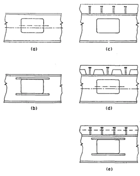
This chapter presents procedures to determine the strength of steel and composite beams with web openings. Compos-ite members may have solid or ribbed slabs, and ribs may be parallel or perpendicular to the steel section. Openings may be reinforced or unreinforced. Fig. 3.1 illustrates the range of beam and opening configurations that can be han-dled using these procedures. The procedures are compatible with the LRFD procedures of the American Institute of Steel Construction, as presented in the Load and Resistance Fac-tor Design Manual of Steel Construction (AISC 1986a). With minor modifications, the procedures may also be used with Allowable Stress Design techniques (see section 3.8).
Design equations and design aids (Appendix A) based on these equations accurately represent member strength with a minimum of calculation. The derivation of these equations is explained in Chapter 5.
The design procedures presented in this chapter are limited to members with a yield strength 65 ksi meeting the AISC criteria for compact sections (AISC 1986b). Other limitations on section properties and guidelines for detail-ing are presented in section 3.7. Design examples are presented in Chapter 4.
3.2 LOAD
AND RESISTANCE FACTORS
The load factors for structural steel members with web open-ings correspond to those used in the AISC Load and Resis-tance Factor Design Specifications for Structural Steel Build-ings (AISC 1986b).
Resistance factors, 0.90 for steel members and 0.85 for composite members, should be applied to both moment and shear capacities at openings.
Members should be proportioned so that the factored loads are less than the design strengths in both bending and shear.
3.3 OVERVIEW
OF DESIGN PROCEDURES
Many aspects of the design of steel and composite members with web openings are similar. At web openings, members may be subjected to both bending and shear. Under the com-bined loading, member strength is below the strength that can be obtained under either bending or shear alone. De-sign of web openings consists of first determining the maxi-mum nominal bending and shear capacities at an opening,
and then obtaining the nominal capacities, and for the combinations of bending moment and shear that occur at the opening.
For steel members, the maximum nominal bending strength, is expressed in terms of the strength of the member without an opening. For composite sections, expres-sions for are based on the location of the plastic neu-tral axis in the unperforated member. The maximum
nomi-Fig. 3.1. Beam and opening configurations, (a) Steel beam with unreinforced opening, (b) steel beam with reinforced opening, (c) composite beam, solid slab, (d) composite beam, ribbed slab with transverse ribs, (e) composite beam with reinforced opening, ribbed slab with logitudinal ribs.
in which
Mu = factored bending moment
Vu = factored shear
Mn = nominal flexural strength
nal shear capacity, is expressed as the sum of the shear capacities, for the regions above and below the
opening (the top and bottom tees).
The design expressions for composite beams apply to open-ings located in positive moment regions. The expressions for steel beams should be used for openings placed in negative moment regions of composite members.
The next three sections present the moment-shear inter-action curve and expressions for used to design members with web openings. Guidelines for member propor-tions follow the presentation of the design equapropor-tions.
are checked using the interaction curve by plot-ting the point If the point lies inside the
R = 1 curve, the opening meets the requirements of Eqs. 3-1 and 3-2, and the design is satisfactory. If the point lies outside the curve, the design is not satisfactory. A large-scale version of Fig. 3.2, suitable for design, is presented in Fig. A.1 of Appendix A.
The value of R at the point
and to be obtained from the applied loads.
3.4 MOMENT-SHEAR INTERACTION
Simultaneous bending and shear occur at most locations within beams. At a web opening, the two forces interact to produce lower strengths than are obtained under pure bend-ing or pure shear alone. Fortunately at web openbend-ings, the interaction between bending and shear is weak, that is, nei-ther the bending strength nor the shear strength drop off rapidly when openings are subjected to combined bending and shear.
The interaction between the design bending and shear strengths, is shown as the solid curve in Fig. 3.2 and expressed as
Additional curves are included in Fig. 3.2 with values of R
ranging from 0.6 to 1.2. The factored loads at an opening,
3.5 EQUATIONS
FOR
MAXIMUM
MOMENT CAPACITY,
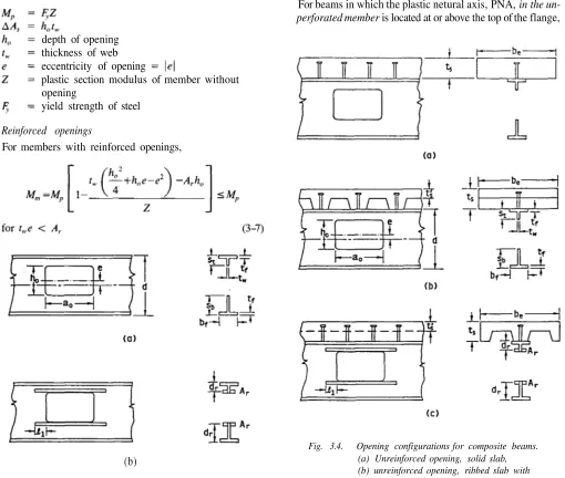
The equations presented in this section may be used to cal-culate the maximum moment capacity of steel (Fig 3.3) and composite (Fig. 3.4) members constructed with compact steel sections. The equations are presented for rectangular open-ings. Guidelines are presented in section 3.7 to allow the ex-pressions to be used for circular openings.
The openings are of length, height, and may have an eccentricity, e, which is measured from the center line of the steel section. For steel members, e is positive, whether the opening is above or below the center line. For compos-ite members, e is positive in the upward direction.
The portion of the section above the opening (the top tee) has a depth while the bottom tee has a depth of If rein-forcement is used, it takes the form of bars above and below the opening, welded to one or both sides of the web. The area of the reinforcement on each side of the opening is
(b)
Fig. 3.3. Opening configurations for steel beams, (a) Unrein-forced opening, (b) reinUnrein-forced opening.
b. Composite beams
The expressions for the nominal capacity of a composite member with a web opening (Fig. 3.4) in pure bend-ing, apply to members both with and without
reinforcement.
Plastic neutral axis above top of flange
For beams in which the plastic netural axis, PNA, in the un-perforated member is located at or above the top of the flange,
Fig. 3.4. Opening configurations for composite beams. (a) Unreinforced opening, solid slab, (b) unreinforced opening, ribbed slab with transverse ribs, (c) reinforced opening, ribbed slab with longitudinal ribs.
a minimum depth of Other dimensions are as shown in Figs. 3.3 and 3.4.
a. Steel beams
The nominal capacity of a steel member with a web open-ing in pure bendopen-ing, is expressed in terms of the ca-pacity of the member without an opening,
Unreinforced openings
For members with unreinforced openings,
Reinforced openings
For members with reinforced openings, depth of opening
thickness of web eccentricity of opening
plastic section modulus of member without opening
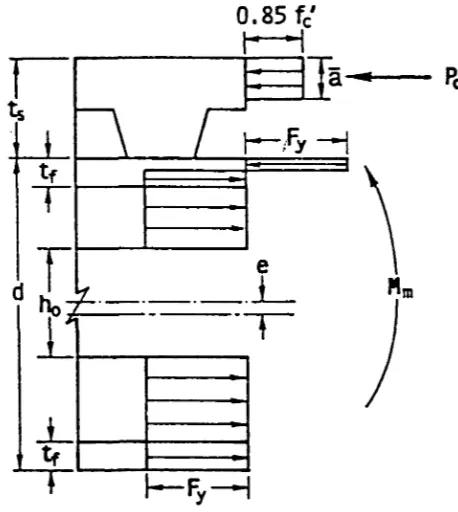
Fig. 3.5. Region at web opening at maximum moment, composite beam.
the value of
may be approximated in terms of the
ca-pacity of the unperforated section,
in which
= nominal capacity of the unperforated composite
section, at the location of the opening
= cross-sectional area of steel in the unperforated
member
= net area of steel section with opening and rein-forcement
= eccentricity of opening, positive upward
Equation 3-9 is always conservative for The values of can be conveniently obtained from Part 4 of the AISC Load and Resistance Factor Design Manual (AISC
1986a).
Plastic neutral axis below top of flange
For beams in which the PNA in the unperforated member
is located below the top of the flange and
the value of may be approximated using
in which
= thickness of slab
= depth of concrete stress block =
= force in the concrete (Fig. 3.5)
is limited by the concrete capacity, the stud capacity from the high moment end of the opening to the support, and the tensile capacity of the net steel section.
(3-11a) (3-11b) (3-11c)
in which
= for solid slabs
= for ribbed slabs with transverse ribs
= for ribbed slabs with longitudinal ribs = number of shear connectors between the high
mo-ment end of the opening and the support
= individual shear connector capacity, including reduc-tion factor for ribbed slabs (AISC 1986b)
= effective width of concrete slab (AISC 1986b)
Equation 3-10 is also accurate for members with the PNA
in the unperforated section located at or above the top of
the flange.
If the more accurate expres-sions given in section 5.5 should be used to calcu-late
3.6 EQUATIONS
FOR MAXIMUM SHEAR
CAPACITY,
The equations presented in this section may be used to cal-culate the maximum shear strength of steel and composite members constructed with compact steel sections. The equa-tions are presented for rectangular openings and used to de-velop design aids, which are presented at the end of this sec-tion and in Appendix A. Guidelines are presented in the next
section to allow the expressions to be used for circular
open-ings. Dimensions are as shown in Figs. 3.3 and 3.4.
The maximum nominal shear capacity at a web opening, is the sum of the capacities of the bottom and top tees. (3-12)
a. General equation
or to the plastic shear capacity of the web of the tee,
Subscripts "b" and "t" indicate the bottom and top tees, respectively.
(3-14)
in which (see Fig. 3.5)
= force in reinforcement along edge of opening
= distance from outside edge of flange to centroid of reinforcement
and = concrete forces at high and low moment ends of opening, respectively. For top tee in
com-posite sections only. See Eqs. 3-15a through 3-16.
and = distances from outside edge of top flange to centroid of concrete force at high and low
mo-ment ends of opening, respectively. For top tee
in composite sections only. See Eqs. 3-17
through 3-18b.
For reinforced openings, s should be replaced by in the calculation of only.
For tees without concrete, . For tees with-out concrete or reinforcement, = 0. For eccentric open-ings,
Equations 3-13 and 3-14 are sufficient for all types of con-struction, with the exception of top tees in composite beams which are covered next.
b. Composite beams
The following expressions apply to the top tee of composite
members. They are used in conjunction with Eqs. 3-13 and 3-4,
the concrete force at the high moment end of the
opening (Eq. 3-14, Fig. 3.6), is
in which = number of shear connectors over the opening.
N in Eq. 3-15b and in Eq. 3-16 include only
connec-tors completely within the defined range. For example, studs on the edges of an opening are not included.
the distances from the top of the flange to the centroid of the concrete force at the high and the low mo-ment ends of the opening, respectively, are
(3-17)
(3-18a)
for ribbed slabs (3-18b) with transverse ribs
For ribbed slabs with longitudinal ribs, is based on the centroid of the compressive force in the concrete consider-ing all ribs that lie within the effective width (Fig. 3.4). In this case, can be conservatively obtained using Eq. 3-18a, replacing the sum of the minimum rib
widths for the ribs that lie within
If the ratio of in Eq. 3-13 exceeds 1, then an
al-ternate expression must be used.
(3-19)
in which for both reinforced and unreinforced openings.
To evaluate in Eq. 3-19, the value of in Eq. 3-15 must be compared with the tensile force in the flange and
reinforcement, since the web has fully yielded in shear.
(3-20)
in which
= width of flange
= thickness of flange
If Eq. 3-20 governs instead of Eq. 3-15,
and must also be recalculated using Eqs. 3-16, 3-17, 3-18,
and 3-14, respectively.
Finally, must not be greater than the pure shear ca-pacity of the top tee,
(3-21)
in which are in ksi
= effective concrete shear area
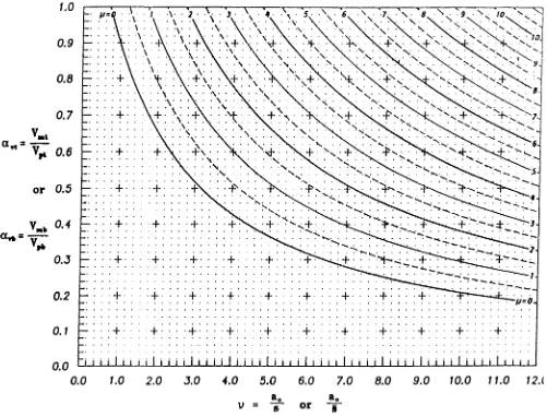
c. Design aids
A design aid representing from Eq. 3-13 is presented in Figs. 3.7 and A.2 for values of ranging from 0 to 12 and values of ranging from 0 to 11. This design aid is applic-able to unreinforced and reinforced tees without concrete, as well as top tees in composite members, with
or less than or equal to 1.
A design aid for from Eq. 3-19 for the top tee in com-posite members with 1 is presented in Figs. 3.8 and
A.3. This design aid is applicable for values of from 0 to
12 and values of from 0.5 to 23. If must be recalculated if Eq. 3-20 controls Pch, and a separate check must be made for (sh) using Eq. 3-21.
The reader will note an offset at = 1 between Figs. A.2 and A.3 (Figs. 3.7 and 3.8). This offset is the result of a
discon-tinuity between Eqs. 3-13 and 3-19 at If appears to be 1 on Fig. A.2 and 1 on Fig. A.3, use = 1.
3.7 GUIDELINES FOR PROPORTIONING
AND DETAILING BEAMS WITH WEB
OPENINGS
To ensure that the strength provided by a beam at a web
open-ing is consistent with the design equations presented in
sec-tions 3.4-3.6, a number of guidelines must be followed.
Un-less otherwise stated, these guidelines apply to unreinforced and reinforced web openings in both steel and composite beams. All requirements of the AISC Specifications (AISC
1986b) should be applied. The steel sections should meet
the AISC requirements for compact sections in both com-posite and non-comcom-posite members. 65 ksi.
a. Stability considerations
To ensure that local instabilities do not occur, consideration must be given to local buckling of the compression flange, web buckling, buckling of the tee-shaped compression zone above or below the opening, and lateral buckling of the com-pression flange.
Fig. 3.7. Design aid relating av, the ratio of the nominal maximum shear strength to the plastic
shear strength of a tee, to v, the ratio of length to depth or effective length to depth
of a tee.
1. Local buckling of compression flange or reinforcement
To ensure that local buckling does not occur, the AISC (AISC 1986b) criteria for compact sections applies. The width to thickness ratios of the compression flange or web reinforce-ment are limited by
(3-22)
in which
b = projecting width of flange or reinforcement t = thickness of flange or reinforcement
= yield strength in ksi
For a flange of width, and thickness, Eq. 3-22 becomes
(3-23)
2. Web buckling
To prevent buckling of the web, two criteria should be met: (a) The opening parameter, should be limited to a maximum value of 5.6 for steel sections and 6.0 for com-posite sections.
(3-24)
in which = length and width of opening, respec-tively, d = depth of steel section
Fig. 3.8. Design aid relating the ratio of the nominal maximum shear strength to the plastic shear strength of the top tee, to the length-to-depth ratio of the tee.
composite members only.
ling, along with an additional criterion from section 3.7bl,
are summarized in Fig. 3.9.
3. Buckling of tee-shaped compression zone
For steel beams only: The tee which is in compression should be investigated as an axially loaded column following the procedures of AISC (1986b). For unreinforced members this
is not required when the aspect ratio of the tee
is less than or equal to 4. For reinforced openings, this check
is only required for large openings in regions of high moment.
4. Lateral buckling
For steel beams only: In members subject to lateral buck-ling of the compression flange, strength should not be governed by strength at the opening (calculated without re-gard to lateral buckling).
(3-25)
in which = thickness of web
If the web qualifies as stocky.
In this case, the upper limit on is 3.0 and the upper limit on (maximum nominal shear capacity) for non-composite sections is in which the
plastic shear capacity of the unperforated web. For composite sections, this upper limit may be increased by which
equals whichever is less.
All standard rolled W shapes (AISC 1986a) qualify as stocky
members.
If then should
be limited to 2.2, and should be limited to 0.45 for both composite and non-composite members.
buck-3. Concentrated loads
No concentrated loads should be placed above an opening. Unless needed otherwise, bearing stiffeners are not
re-quired to prevent web crippling in the vicinity of an opening due to a concentrated load if
(3-27a)
(3-27b)
and the load is placed at least from the edge of the opening,
or (3-28a)
(3-28b)
and the load is placed at least d from the edge of the opening. In any case, the edge of an opening should not be closer than a distance d to a support.
4. Circular openings
Circular openings may be designed using the expressions in sections 3.5 and 3.6 by using the following substitutions for
Unreinforced web openings:
(3-29a) (3-29b) (3-29c)
in which diameter of circular opening. Reinforced web openings:
(3-30a) (3-30b)
5. Reinforcement
Reinforcement should be placed as close to an opening as possible, leaving adequate room for fillet welds, if required on both sides of the reinforcement. Continuous welds should be used to attach the reinforcement bars. A fillet weld may be used on one or both sides of the bar within the length of the opening. However, fillet welds should be used on both sides of the reinforcement on extensions past the opening. The required strength of the weld within the length of the
opening is,
(3-31)
in which
= required strength of the weld
In members with unreinforced openings or reinforced openings with the reinforcement placed on both sides of the web, the torsional constant, J, should be multiplied by
(3-26)
in which unbraced length of compression flange
In members reinforced on only one side of the web, 0 for the calculation of in Eq. 3-26. Members
reinforced on one side of the web should not be used for
long laterally unsupported spans. For shorter spans the lateral bracing closest to the opening should be designed for an
ad-ditional load equal to 2 percent of the force in the compres-sion flange.
b. Other considerations
1. Opening and tee dimensions
Opening dimensions are restricted based on the criteria in section 3.7a. Additional criteria also apply.
The opening depth should not exceed 70 percent of the section depth The depth of the top tee should
not be less than 15 percent of the depth of the steel section
The depth of the bottom tee, should not be less than 0.15d for steel sections or 0.l2d for composite sections. The aspect ratios of the tees should not be greater than 12 12).
2. Comer radii
The corners of the opening should have minimum radii at
least 2 times the thickness of the web, which-ever is greater.
In addition to the requirements in Eqs. 3-37 and 3-38,
openings in composite beams should be spaced so that
(3-39a)
(3-39b)
c. Additional criteria for composite beams
In addition to the guidelines presented above, composite members should meet the following criteria.
1. Slab reinforcement
Transverse and longitudinal slab reinforcement ratios should be a minimum of 0.0025, based on the gross area of the slab, within a distance d or whichever is greater, of the open-ing. For beams with longitudinal ribs, the transverse rein-forcement should be below the heads of the shear connectors.
2. Shear connectors
In addition to the shear connectors used between the high
moment end of the opening and the support, a minimum of
two studs per foot should be used for a distance d or
whichever is greater, from the high moment end of the open-ing toward the direction of increasing moment.
3. Construction loads
If a composite beam is to be constructed without shoring, the section at the web opening should be checked for ade-quate strength as a non-composite member under factored dead and construction loads.
3.8 ALLOWABLE
STRESS DESIGN
The safe and accurate design of members with web open-ings requires that an ultimate strength approach be used. To accommodate members designed using ASD, the expressions presented in this chapter should be used with = 1.00 and a load factor of 1.7 for both dead and live loads. These fac-tors are in accord with the Plastic Design Provisions of the AISC ASD Specification (1978).
= 0.90 for steel beams and 0.85 for composite beams
= cross-sectional area of reinforcement above or
be-low the opening.
The reinforcement should be extended beyond the
open-ing by a distance whichever is
greater, on each side of the opening (Figs 3.3 and 3.4). Within each extension, the required strength of the weld is
(3-32)
If reinforcing bars are used on only one side of the web, the section should meet the following additional
requirements.
= factored moment and shear at centerline of opening, respectively.
6. Spacing of openings
Openings should be spaced in accordance with the
follow-ing criteria to avoid interaction between openfollow-ings.
Rectangular openings: (3-37a)
(3-37b)
Circular openings: (3-38a)
(3-38b)
in which S = clear space between openings.
Rev. 3/1/03
Chapter 4
DESIGN SUMMARIES AND EXAMPLE PROBLEMS
4.1 GENERAL
Equations for maximum bending capacity and details of opening design depend on the presence or absence of a com-posite slab and opening reinforcement. However, the over-all approach, the basic shear strength expressions, and the procedures for handling the interaction of bending and shear are identical for all combinations of beam type and opening configuration. Thus, techniques that are applied in the de-sign of one type of opening can be applied to the dede-sign of all. Tables 4.1 through 4.4 summarize the design sequence, de-sign equations and dede-sign aids that apply to steel beams with unreinforced openings, steel beams with reinforced openings, composite beams with unreinforced openings, and compos-ite beams with reinforced openings, respectively. Table 4.5
summarizes proportioning and detailing guidelines that ap-ply to all beams.
Sections 4.2 through 4.6 present design examples. The ex-amples in sections 4.2, 4.4, 4.5, and 4.6 follow the LRFD approach. In section 4.3, the example in section 4.2 is re-solved using the ASD approach presented in section 3.8.
A typical design sequence involves cataloging the proper-ties of the section, calculating appropriate properproper-ties of the opening and the tees, and checking these properties as de-scribed in sections 3.7a and b. The strength of a section is determined by calculating the maximum moment and shear capacities and then using the interaction curve (Fig. A.1) to determine the strength at the opening under the combined effects of bending and shear.
Designs are completed by checking for conformance with additional criteria in sections 3.7b and c.
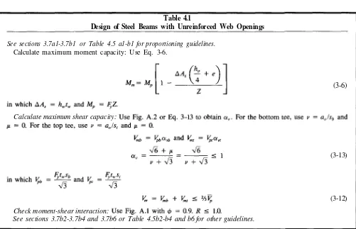
Table 4.1
Design of Steel Beams with Unreinforced Web Openings
See sections 3.7a1-3.7b1 or Table 4.5 a1-b1 for proportioning guidelines. Calculate maximum moment capacity: Use Eq. 3-6.
(3-6)
(3-13)
(3-12) Calculate maximum shear capacity:
Check moment-shear interaction:
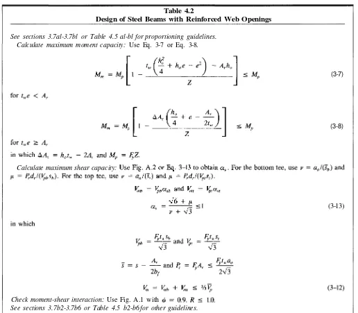
Table 4.2
Design of Steel Beams with Reinforced Web Openings
(3-7)
(3-8)
(3-13) See sections 3.7al-3.7bl or Table 4.5 al-bl for proportioning guidelines.
Calculate maximum moment capacity: Use Eq. 3-7 or Eq. 3-8.
Check moment-shear interaction: Use Fig. A.1 with
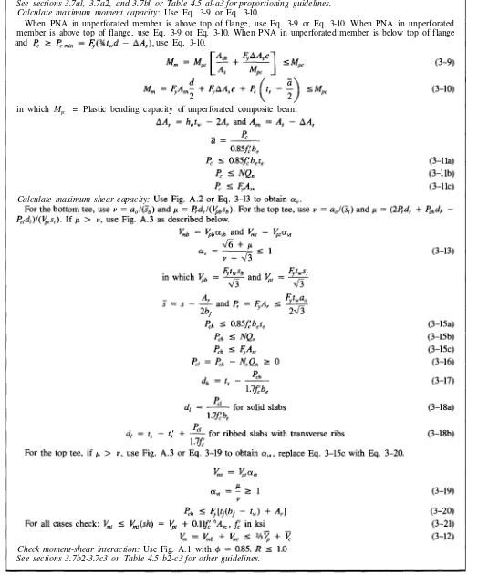
Table 4.3
Design of Composite Beams with Unreinforced Web Openings
See sections 3.7a1, 3.7a2, and 3.7b1 or Table 4.5 a1-a3 for proportioning guidelines. Calculate maximum moment capacity: Use Eq. 3-9 or Eq. 3-10.
When PNA in unperforated member is above top of flange, use Eq. 3-9 or Eq. 3-10. When PNA in unperforated
member is below top of flange and use Eq. 3-10.
(3-9)
(3-10)
in which Mpc = Plastic bending capacity of unperforated composite beam
and
(3-11a) (3-11b) (3-11c) Calculate maximum shear capacity: Use Fig. A.2 or Eq. 3-13 to obtain For the bottom tee, use and
For the top tee, use and If use Fig. A.3 as described below.
(3-13)
(3-15a)
(3-15b) (3-15c) (3-16)
(3-17)
(3-18a)
(3-18b)
for ribbed slabs with transverse ribs
For the top tee, if use Fig. A.3 or Eq. 3-19 to obtain and replace Eq. 3-15c with Eq. 3-20, with
(3-19)
(3-20) For all cases check:
(3-21) (3-12) Check moment-shear interaction: Use Fig. A.1 with
Table 44
Design of Composite Beams with Reinforced Web Openings
See sections 3.7al, 3.7a2, and 3.7bl or Table 4.5 al-a3 for proportioning guidelines. Calculate maximum moment capacity: Use Eq. 3-9 or Eq. 3-10.
When PNA in unperforated member is above top of flange, use Eq. 3-9 or Eq. 3-10. When PNA in unperforated member is above top of flange, use Eq. 3-9 or Eq. 3-10. When PNA in unperforated member is below top of flange
and use Eq. 3-10.
in which Mpc = Plastic bending capacity of unperforated composite beam
Calculate maximum shear capacity:
Check moment-shear interaction: Use Fig. A.1 with
Table 4.5
Summary of Proportioning and Detailing Guidelines
These guidelines apply to both steel and composite members, unless noted otherwise.
a. Section properties and limits on 1. Beam dimensions and limits on
(a) Width to thickness ratios of compression flange and web reinforcement, must not exceed 65 ksi) (section 3.7al).
(b) The width to thickness ratio of the web, , must not exceed . If the ratio is
must not exceed 3.0, and must not exceed for steel beams + for composite beams. If the ratio is must not exceed 2.2, and must not exceed 0.45
whichever is less] (section 3.7a2). 2. Opening dimensions (See Fig. 3.9)
(a) Limits on are given in a.l.(b) above. (b) must not exceed (section 3.7bl).
(c) The opening parameter, must not exceed 5.6 for steel beams or 6.0 for composite beams (section 3.7a2).
3. Tee dimensions
(a) Depth (composite)] (section 3.7bl).
(b) Aspect ratio (section 3.7bl).
b. Other considerations
1. Stability considerations. Steel beams only
(a) Tees in compression must be designed as axially loaded columns. Not required for unreinforced openings if 4 or for reinforced openings, except in regions of high moment (section 3.7a3).
(b) See requirements in section 3.7a4 for tees that are subject to lateral buckling. 2. Corner radii
Minimum radii = the greater of (section 3.7b2). 3. Concentrated loads
No concentrated loads should be placed above an opening. Edge of opening should not be closer than d to a sup-port. See section 3.7b3 for bearing stiffener requirements.
4. Circular openings
See section 3.7b4 for guidelines to design circular openings as equivalent rectangular openings. 5. Reinforcement
See section 3.7b5 for design criteria for placement and welding of reinforcement. 6. Spacing of openings
See section 3.7b6 for minimum spacing criteria.
c. Additional criteria for composite beams
1. Slab reinforcement
Minimum transverse and longitudinal slab reinforcement ratio within d or (whichever is greater) of the open-ing is 0.0025, based on gross area of slab. For beams with longitudinal ribs, the transverse reinforcement should be below the heads of the shear connectors (section 3.7cl).
2. Shear connectors
In addition to shear connectors between the high moment end of opening and the support, use a minimum of two studs per foot for a distance d or (whichever is greater) from high moment end of opening toward direction of increasing moment (section 3.7c2).
3. Construction loads
4.2 EXAMPLE
1:
STEEL BEAM WITH
UNREINFORCED OPENING
A W24X55 section supports uniform loads = 0.607
kips/ft and = 0.8 kips/ft on a 36-foot simple span. The
beam is laterally braced throughout its length. ASTM A36 steel is used.
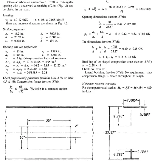
Determine where an unreinforced 10x20 in. rectangular opening with a downward eccentricity of 2 in. (Fig. 4.1) can
be placed in the span.
Loading:
= 1.2 X 0.607 + 1.6 x 0.8 = 2.008 kips/ft
Shear and moment diagrams are shown in Fig. 4.2.
Buckling of tee-shaped compression zone (section 3.7a3):
Check not required
Lateral buckling (section 3.7a4): No requirement, since compression flange is braced throughout its length
Maximum moment capacity:
For the unperforated section:
in.-kips
Allowable locations of opening:
The factored moment, factored shear, and values
of will be tabulated at 3-ft intervals across the beam.
To determine if the opening can be placed at each
loca-tion, the R value for each point is
ob-tained from the interaction diagram, Fig. A.1.
Figure A.1 is duplicated in Fig. 4.3, which shows the lo-cation of each point on the interaction diagram. The open-ing may be placed at a location if 1. The results are presented in Table 4.6. The acceptable range for opening lo-cations is illustrated in Fig. 4.4.
Table 4.6 shows that the centerline of the opening can be placed between the support and a point approximately ft
from the support, on either side of the beam. The opening
location is further limited so that the edge of the opening
can be no closer than a distance d to the support (section 3.7b3). Thus, the opening centerline must be located at least
in., say 34 in., from the support (section 3.7b2).
Corner radii:
The corner radii must be or
larger.
4.3 EXAMPLE
1A:
STEEL BEAM WITH
UNREINFORCED OPENING—ASD
APPROACH
Repeat Example 1 using the ASD Approach described in sec-tion 3.8.
Loading:
= 1.7 X 0.607 + 1.7 x 0.8 = 2.392 kips/ft
The values of factored shear and moment in Example 1 are thus multiplied by the factor 2.392/2.008 = 1.191.
Section properties, opening and tee properties: See Example 1.
Check proportioning guidelines (section 3.7al-3.7bl or Table 4.5 al-bl):
See Example 1.
Maximum moment capacity:
From Example 1, 0.9 3766 in.-kips.
For ASD, = 4184 in.-kips.
Maximum shear capacity:
From Example 1, 0.9 = 54.28 kips. For ASD, = 1.0; 60.31 kips.
Allowable locations of openings:
As with Example 1, the factored moment factored shear, and values of and will be tabu-lated at 3-ft intervals across the beam.
To determine if the opening can be placed at each
loca-tion, the R value for each point is
ob-tained from the interaction diagram, Fig. A.1. The opening may be placed at a location if 1. The results are presented in Table 4.7.
Table 4.7 shows that the centerline of the opening can be placed between the support and a point 12 ft from the sup-port, on either side of the beam. This compares to a value of 14.6 ft obtained in Example 1 using the LRFD approach. As in Example 1, the opening location is further limited so that the edge of the opening can be no closer than a distance d = 34 in. to the support (section 3.7b3).
Corner radii (section 3.7b2): See Example 1.
44 EXAMPLE
2:
STEEL BEAM WITH
REINFORCED OPENING
A concentric 11x20 in. opening must be placed in a Wl8x55 section (Fig. 4.5) at a location where the factored shear is 30 kips and the factored moment is 300 ft-kips (3600 in.-kips). The beam is laterally braced throughout its length.
= 50 ksi.
Can an unreinforced opening be used? If not, what rein-forcement is required?
Fig. 4.4. Allowable opening locations for Example 1.
Table 4.6
Allowable Locations for Openings, Example 1
been skipped. If reinforcement is needed, the reinforcement must meet this requirement.)
Web and limit on (section 3.7a2):
Fig. 4.5. Details for Example 2.
1
Allowable Locations for Openings, Example 1A
Point
since all W shapes meet this requirement
Check proportioning guidelines (sections 3.7al-3.7bl or Table 4.5 al-bl):
Compression flange and reinforcement (section 3.7al):
(Since a W18x35 is a compact section this check could have
Opening dimensions (section 3.7bl):
Buckling of tee-shaped compression zone (section 3.7a3): 4. Check for buckling if reinforcement is not used.
Lateral buckling (section 3.7a4): No requirement, since compression flange is braced throughout its length.
Maximum moment capacity: For the unperforated section: 5600 in.-kips
Using Eq. 3-6,
Design reinforcement and check strength:
Reinforcement should be selected to reduce R to 1.0. Since the reinforcement will increase of a steel member only slightly, the increase in strength will be obtained primarily through the effect of the reinforcement on the shear capac-ity, remains at approximately 0.79, R = 1.0
will occur for 0.80 (point 1 on Fig. 4.6).
Try
From Fig. A.1 (Fig. 4.6, point 2), R = 0.96 1.0 OK The section has about 4 percent excess capacity.
Maximum shear capacity:
Bottom and top tees:
Check interaction:
By inspection, R > 1.0. The strength is not adequate and reinforcement is required.
Check strength:
(a) Maximum moment capacity:
(b) Maximum shear capacity:
= 0.90 × 50 × 0.656 = 29.5 kips within each ex-tension. Use extensions of = 20/4 = 5 in.,
× 0.656/(2 × 0.39) = 1.46 in. Use 5 in. The total length of the reinforcement = 20.0 + 2 × 5.0 =
30.0 in.
Assume E70XX electrodes, which provide a shear strength of the weld metal = 0.60 × 70 = 42 ksi (AISC 1986a). A fillet weld will be used on one side of the reinforcement bar, within the length of the opening. Each in. weld will provide a shear capacity of × 0.707 × = 0.75 × 42 × 20 × 0.707 × = 27.8 kips.
For = 59.0 kips, with the reinforcement on one side of the web, 59.0/27.8 = 2.12 sixteenths are required. Use a in. fillet weld. [Note the minimum size of fillet weld for this material is in.]. Welds should be used on both sides of the bar in the extensions. By inspection, the weld size is identical.
According to AISC (1986b), the shear rupture strength of the base metal must also be checked. The shear rupture strength = , in which = 0.75,
tensile strength of base metal, and = net area subject to shear. This requirement is effectively covered for the steel section by the limitation that which is based on = 0.90 instead of = 0.75, but uses
0.58 in place of . For the reinforcement, the shear
rupture force 52.7 kips.
0.75 × 0.6 × 58 ksi × in. = =196 kips 52.7, OK. The completed design is illustrated in Fig. 4.7.
4.5 EXAMPLE
3: COMPOSITE BEAM
WITH UNREINFORCED OPENING
Simply supported composite beams form the floor system of an office building. The 36-ft beams are spaced 8 ft apart and support uniform loads of = 0.608 kips/ft and 0.800 kips/ft. The slab has a total thickness of 4 in. and will be placed on metal decking. The decking has 2 in. ribs on 12 in. centers transverse to the steel beam. An A36 W21×44 steel section and normal weight concrete will be used. Nor-mal weight concrete (w = 145 = 3 ksi will be used.
Can an unreinforced 11×22 in. opening be placed at the quarter point of the span? See Fig. 4.8.
Select reinforcement:
Check to see if reinforcement may be placed on one side of web (Eqs. 3-33 through 3-36):
Fig. 4.6. Moment-shear interaction diagram for Example 2. Therefore, reinforcement may be placed on one side of the web.
From the stability check [Eq. (3-22)], 9.2. Use
Comer radii (section 3.7b2) and weld design:
The corner radii must be = 0.78 in. in. Use in. or larger.
The weld must develop 0.90 × 2 × 32.8 = 59.0 kips within the length of the opening and
Loading:
= 1.2 × 0.608 + 1.6 × 0.800 = 2.01 kips/ft
At the quarter point:
18.1 kips
Rev. 3/1/03
Fig. 4.7. Completed design of reinforced opening for Example 2. Shear connector parameters:
Use in. studs (Note: maximum allowable stud height is used to obtain the maximum stud capacity). Following the procedures in AISC (1986b),
Opening and tee properties:
(positive upward for composite members)
Try 1 stud per rib:
Check proportioning guidelines (sections 3.7al, 3.7a2, and 3.7bl or Table 4.5 a1-a3):
Compression flange (section 3.7a1):
OK, since all W shapes meet this requirement
Tee dimension (section 3.7bl):
Maximum moment capacity:
Use Eqs. 3-11a, 3-11b, and 3-11c to calculate the force in the concrete:
By inspection, the PNA in the unperforated section will be below the top of the flange. Therefore, use Eq. 3-10 to calculate
Maximum shear capacity:
(a) Bottom tee:
(b) Top Tee:
The value of µ must be calculated for the top tee. The net area of steel in the top tee is
The force in the concrete at the high moment end of the opening is obtained using Eqs. 3-15a, b and c.
Fig. 4.9. Top tee under maximum shear for Example 3. Fig. 4.10. Moment-shear interaction diagram for Example 3. Using Fig. A.1 (reproduced in Fig. 4.10) the point (0.585, 0.845) yields a value of R = 0.93. Therefore, the opening can be placed at the quarter point of the span.
The design shear and moment capacities at the opening are
4.6 EXAMPLE
4:
COMPOSITE GIRDER
WITH UNREINFORCED AND
REINFORCED OPENINGS
A 40-foot simply-supported composite girder supports fac-tored loads of 45 kips at its third points [Fig. 4.11(a)]. The slab has a total thickness of in. and is cast on metal deck-ing with 3 in. deep ribs that are parallel to the A36 W18X60 steel beam. The ribs are spaced at 12 in., and the girders are spaced 40 ft apart. The concrete is normal weight;
= 4 ksi. The design calls for pairs of in. shear studs spaced every foot in the outer third of the girder, starting
6 in. from the support, and single studs every foot in the
middle third of the girder. The design moment capacity of the unperforated member, ft-kips in the middle third of the member.
1. Can an unreinforced 10x24 in. opening with a down-ward eccentricity of 1 in. [Fig. 4.12(a)] be placed in the middle third of the beam? If not, how much rein-forcement is necessary?
2. Can a concentric unreinforced opening of the same size [Fig. 4.12(b)] be placed ft from the centerline of the support? If not, how much reinforcement is required?
Loading:
The factored shear and moment diagrams are shown in Figs
4.11 (b) and (c).
Fig. 4.11. Shear and moment diagrams for Example 4.
Fig. 4.12. Details for Example 4. (a) Eccentric opening, (b) concentric opening.
Section properties:
Opening and tee properties:
Without reinforcement,
Shear connector strength:
Check proportioning guidelines (sections 3.7al, 3.7a2, and 3.7a3 or Table 4.5 a1-a3):
in middle third OK, by inspection, ft from support
1. Opening in middle one-third of beam
Figure 4.11(b) shows that the shear is very low and the mo-ment is very nearly constant in the middle third of the girder. The maximum factored moment is 614 ft-kips (7368 in-kips), which is very close to = 621 ft-kips (7452 in .-kips) for unperforated section. Reinforcement will be required to compensate for the opening. Since the section is in nearly pure bending, the reinforcement will be selected based on bending alone, i.e.,
The PNA in the unperforated section is above the top of the flange. Therefore, Eq. 3-9 can be used to calculate the required area of reinforcement. (It should be very close to the area removed by the opening.)
Fig. 4.13. Completed design of reinforced, eccentric opening
located in middle one-third of beam in Example 4.
A check of Eqs. 3-33 through 3-36 shows that the rein-forcement must be placed on both sides of the web. To
pre-vent local buckling, in. bars on each
side of the web, above and below the opening. Extend the bars in. on either side of the opening for a total length of 36 in. Design the welds in accordance with Eqs. 3-31 and 3-32 (see Example 2).
The completed design is illustrated in Fig. 4.13.
2. Opening ft from support
The eccentricity is zero at this location [Fig. 4.12(b)]. 46.0 kips and = 300 ft-kips (3600 in-kips) (Fig. 4.11).
Maximum moment capacity without reinforcement: The PNA is below the top of the flange in the unperforated section. Therefore, Eq. 3-10 will be used to calculate The force in the concrete is obtained using Eqs. 3-11 a, b,
and c.
Web and limits on Vm (section 3.7a2):
since all W shapes meet this requirement
Opening dimensions (section 3.7bl):
Tee dimensions (section 3.7b1):
(b) Top tee:
The value of [Eq. 3-14] must be calculated for the top tee. The force at the high moment end of the opening, is obtained using Eqs. 3-15a, b, and c. Noting that Eqs. 3-15a and b are the same as Eqs. 3-1 1a and b, the limitations based on concrete and stud capacity are identical to those obtained for in the calculation of above. This leaves Eq.
3-15c.
242 kips CONTROLS
The force in the concrete at the low moment end of the opening, is obtained using Eq. 3-16. With the shear
studs placed in pairs every foot, starting 6 in. from the
cen-terline of the support, Note that the definitions for N and N0 require the studs to be completely within the ap-plicable range to be counted. This means that the studs lo-cated just at the ends of the opening are not included in and the studs at the high moment end of the opening are not counted in N.
the distances from the top of the flange to the centroids of respectively, are calculated using Eqs. 3-17 and 3-18a. Since the ribs are parallel to the steel beams, in Eq. 3-18a is conservatively replaced by
the sum of the minimum rib widths that lie within
Since Eq. 3-19 or Fig A.3 should be used to calcu-late In addition, when is limited by the ten-sile capacity of the flange plus reinforcement (if any), Eq. 3-20.
This value is less than the current value of (242 kips).
Therefore, must also be recalculated. The
new values are as follows:
By inspection, the section does not have adequate strength. Using Fig A.1 (reproduced in Fig. 4.14), the point (1.114, 0.674), point 1 on Fig. 4.14, yields a value of R = 1.21> 1.
Design reinforcement and check strength:
in from 0 to And the shear capacity of the top tee will be enhanced due to increases in from the addition of and an increase in The increase in is obtained because its value is currently limited by the tensile capacity of the top flange alone (Eq. 3-20).
Fig. 4.14. Moment-shear interaction diagram for opening located ft from support in Example 4.
Maximum moment capacity:
Use Eqs. 3-11a, 3-11b, and 3-11c to calculate the force in the concrete:
Maximum shear capacity:
(a) Bottom tee:
(b) Top tee:
Using Fig A.1, the point (0.792, 0.628), point 2 in Fig. 4.14, yields a value of R = 0.905 < 1 OK. In fact, the section now has about 10 percent excess capacity. If this opening detail will be used many times in the structure, it would be worthwhile to improve the design by reducing the area of reinforcement.
Select reinforcement:
Check to see if reinforcement may be placed on one side of the web (Eqs. 3-33 through 3-36).
Fig. 4.15. Completed design of reinforced, concentric opening located ft from support in Example 4.
Therefore, reinforcement may be placed on one side of the web.
From the stability check (Eq. 3-22),
in. bar on one side of the web, above and below the opening 3.93 in. and is somewhat less than the value originally assumed. However, the section ca-pacity is clearly adequate.
Extend the reinforcement in. on either side of the opening for a total length of 36 in. Design the welds in accordance with Eqs. 3-31 and 3-32 (see Example 2).
Other considerations:
The corner radii (section 3.7b2) must be in. or larger.
Within a distance d = 18.24 in. or 24 in. (controls) of the opening, the slab reinforcement ratio should be a mini-mum of 0.0025, based on the gross area of the slab (section 3.7cl). The required area of slab reinforcement, in both logitudinal and transverse directions is
In addition to the shear connectors between the high mo-ment end of the opening and the support, a minimum of two studs per foot should be used for a distance d or (con-trols in this case) from the high moment end of the opening toward the direction of increasing moment (section 3.7c2). This requirement is satisfied by the original design, which calls for pairs of studs spaced at 1 foot intervals in the outer thirds of the beam.
Finally, if shoring is not used, the beam should be checked for construction loads as a non-composite member (section 3.7c3).
Chapter 5
BACKGROUND AND COMMENTARY
5.1 GENERAL
This chapter provides the background and commentary for the design procedures presented in Chapter 3. Sections 5.2a through 5.2g summarize the behavior of steel and
compos-ite beams with web openings, including the effects of open-ings on stress distributions, modes of failure, and the gen-eral response of members to loading. Section 5.2h provides the commentary for section 3.2 on load and resistance fac-tors, while sections 5.3 through 5.7 provide the commentary for sections 3.3 through 3.7 on design equations and guide-lines for proportioning and detailing beams with web
openings.
5.2 BEHAVIOR
OF MEMBERS WITH
WEB OPENINGS
a. Forces acting at opening
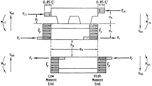
The forces that act at opening are shown in Fig. 5.1. In the figure,
a composite beam is illustrated, but the equations that follow pertain equally well to steel members. For positive bending, the section below the opening, or bottom tee, is subjected to
a tensile force, shear, and secondary bending moments, The section above the opening, or top tee, is sub-jected to a compressive force, shear, and secondary bending moments, . Based on equilibrium,
b. Deformation and failure modes
The deformation and failure modes for beams with web open-ings are illustrated in Fig. 5.2. Figures 5.2(a) and 5.2(b) illus-trate steel beams, while Figs. 5.2(c) and 5.2(d) illusillus-trate com-pbsite beams with solid slabs.
High moment-shear ratio
The behavior at an opening depends on the ratio of moment to shear, M/V (Bower 1968, Cho 1982, Clawson & Darwin 1980, Clawson & Darwin 1982a, Congdon & Redwood 1970, Donahey & Darwin 1986, Donahey & Darwin 1988, Granada 1968).
Fig. 5.2. Failure modes at web openings, (a) Steel beam, pure bending, (b) steel beam, low moment-shear ratio,
(c) composite beam with solid slab, pure bending, (d) composite beam with solid slab, low moment-shear ratio.
Fig. 5.1. Forces acting at web opening.
(5-1) (5-2) (5-3) (5-4)
(5-5)
in which
total shear acting at an opening
primary moment acting at opening center line length of opening
distance between points about which secondary bend-ing moments are calculated
Rev. 3/1/03 Rev.
Medium and low moment-shear ratio
AsM/Vdecreases, shear and the secondary bending moments increase, causing increasing differential, or Vierendeel,
defor-mation to occur through the opening [Figs. 5.2(b) and 5.2(d)]. The top and bottom tees exhibit a well-defined change in curvature.
For steel beams [Fig. 5.2(b)], failure occurs with the
for-mation of plastic hinges at all four corners of the opening. Yielding first occurs within the webs of the tees.
For composite beams [Fig. 5.2(d)], the formation of the plas-tic hinges is accompanied by a diagonal tension failure within the concrete due to prying action across the opening. For
mem-bers with ribbed slabs, the diagonal tension failure is manifested as a rib separation and a failure of the concrete
around the shear connectors (Fig. 5.3). For composite
mem-bers with ribbed slabs in which the rib is parallel to the beam,
failure is accompanied by longitudinal shear failure in the slab (Fig. 5.4).
For members with low moment-shear ratios, the effect of
secondary bending can be quite striking, as illustrated by the
stress diagrams for a steel member in Fig. 5.5 (Bower 1968) and the strain diagrams for a composite member with a ribbed slab in Fig. 5.6 (Donahey & Darwin 1986). Secondary bend-ing can cause portions of the bottom tee to go into compres-sion and portions of the top tee to go into tencompres-sion, even though
the opening is subjected to a positive bending moment. In com-posite beams, large slips take place between the concrete deck
and the steel section over the opening (Fig. 5.6). The slip is enough to place the lower portion of the slab in compression
Fig. 5.3. Rib failure and failure of concrete around shear connectors in slab with transverse ribs.
at the low moment end of the opening, although the adjacent steel section is in tension. Secondary bending also results in tensile stress in the top of the concrete slab at the low moment
end of the opening, which results in transverse cracking.
Failure
Web openings cause stress concentrations at the corners of the openings. For steel beams, depending on the proportions of the top and bottom tees and the proportions of the opening with respect to the member, failure can be manifested by
gen-eral yielding at the corners of the opening, followed by web tearing at the high moment end of the bottom tee and the low
moment end of the top tee (Bower 1968, Congdon &
Red-wood 1970, RedRed-wood & McCutcheon 1968). Strength may
be reduced or governed by web buckling in more slender members (Redwood et al. 1978, Redwood & Uenoya 1979). In high moment regions, compression buckling of the top
tee is a concern for steel members (Redwood & Shrivastava
1980). Local buckling of the compression flange is not a con-cern if the member is a compact section (AISC 1986b).
For composite beams, stresses remain low in the concrete until well after the steel has begun to yield (Clawson & Dar-win 1982a, Donahey & DarDar-win 1988). The concrete
contrib-utes significantly to the shear strength, as well as the
flex-ural strength of these beams at web openings. This contrasts with the standard design practice for composite beams, in which the concrete deck is used only to resist the bending moment, and shear is assigned solely to the web of the steel section.
For both steel and composite sections, failure at web
open-ings is quite ductile. For steel sections, failure is preceded by large deformations through the opening and significant yielding of the steel. For composite members, failure is
preceded by major cracking in the slab, yielding of the steel, and large deflections in the member.
First yielding in the steel does not give a good repre-sentation of the strength of either steel or composite sec-tions. Tests show that the load at first yield can vary from 35 to 64 percent of the failure load in steel members (Bower 1968, Congdon & Redwood 1970) and from 17 to 52 percent
of the failure load in composite members (Clawson &
Dar-win 1982a, Donahey & DarDar-win 1988).
Fig. 5.4. Longitudinal rib shear failure.