1
Smart Grid Control with Fuzzy Integrator for Micro Hydro
Connected to Low Voltage Distribution PT. PLN (Persero)
Lie Jasa1 , IGA Raka Agung2, I Putu Ardana3, Ardyono4 ,Mauridhy Hery Purnomo5 1,2,3
Electrical Engineering Department,Udayana University, Bali, Indonesia 4,5
Electrical Engineering Department Sepuluh Nopember Institute of Technology Surabaya, Indonesia 1[email protected], 2[email protected], 3[email protected], 4[email protected], 5[email protected]
Abstract— The capacity of electrical energy supply PT. PLN (persero) insufficient to public demand in Indonesia. Micro Hydro Power Plant ( MHPP ) is a small-scale power plants which relatively easy to developed in remote areas. The generated energy by MHPP must be transmitted to the power distribution network. In this study researchers wanted to answer the problems how to make a model auto control which connects the MHPP with power network distribution PT.PLN(Persero).The results of this studies is a MHPP can be auto controlled by I, PI, PID and Fuzzy-I controller. Smart control of Fuzzy-I controller make the system to stable with a small overshoot values. It is better than I, PI or PID controller.
Keyword : Micro hydro, Energy, Fuzzy
I. INTRODUCTION
Impact of excessive energy use for this is the cause of air pollution, global warming and climate change. Water energy is an environmentally friendly energy source, green, unlimited and renewable nature. All countries in the world today continues to conduct research on water energy, wind and solar, which is used as one of the future energy development policy options. Proven installation of Renewable Energy is currently in parts of the world increased to 30%.[1],[2]
The energy plays an important role for population in the Indonesia. The energy demand is significantly increases every year but the energy resource is limited and decreases especially conventional energy. Hydropower[3] is one of clean energy resources in the world. It is also the most reliable and effectively cost renewable energy resource among the others. Small hydropower schemes are getting increasingly popular because of its simplicity design, easy in operation, and lower model control system about it.
This study focused on discussing the frequency control of the generator mounted on the MHPP to be set for frequency changes (Δf) by using a low voltage reference of PT. PLN(Persero). This control is using fuzzy logic consisting of 7- rule member’s ship function to control error (e) and change of error (de).
II. LETERATURE REVIEW A. Hydraulics power theory
Theorem of water flow is used to determine the amount of energy that can be generated from the flowing water. The total extractable hydraulic power from the flowing water is given by the expression of Pin= ρ x g x Q x H, where Pin is the
hydraulic power input to the wheels (W), ρ is the density of
water (kg/m3), g is the acceleration due to gravity (9,81m/s2), Q is the volumetric water flow rate (m3/s) and H is the difference in total energy line upstream and downstream of the
wheel (m). The angular velocity ω (rad/s) of the wheels is
calculated from the number of revolutions N at the given load
in revolutions per minute (RPM) of the wheel as : ω = 2 x π x
N/60. The shaft torque τ (Nm) is the product of the force F of water striking the blades of the water wheel (N) and the moment arm length (m) which, in this case, is the radius of the pulley r. Force is equal to the differences in the mass obtained from the two load cells time the acceleration due to gravity. τ = m x g x r. Subsequently the mechanical power output Pout available at the wheel shaft is determined from the measured
torque τ and the corresponding angular speed of the wheel ω
as : Pout= ω x τ = 2 x π x N x τ/60. By calculating the power of
output and input, the mechanical efficiency η of the wheel is
therefore: η = Pout / Pin x 100%
Automatic control system of micro-hydro is built in a closed loop. First some water are flow in the valve, it continue to the spill way and rotate the turbine. The control system of MHPP as shown at Figure 1
B. Governor Controller
2 Figure 1 : Micro Hydro Power Plant
The block control of system micro hydro[7] is set firstly the volume of water that passes through the penstock with a valve . The water from the penstock is to turn a turbine that coupled with the generator. The output of the generator will be paired frequency sensors and compared with a reference frequency of PT . PLN ( Persero ) . The difference value of frequency will be used by the controller to set the valve again, and so on . As shown in Figure 2
Figure 2 : Design System Control Micro Hydro[5]
C. Micro Hydro Controller
The control system of MHPP been developed in many studies, such as PI control and PID. Everything is based on conventional, because to settings of gain Ki, Kp and Kd by trial and error. In this study the authors emphasize the Fuzzy integrator controller. Alternative controller of MHPP can be choices as shown at figure 3. Where the fuzzy pre-compensation function of regulating of errors that appears before input into the control Integrator.
The equations (1) error as shown in. yp = yin – e where
e = y −y (1)
e( k) = y ( k)−y ( k) (2)
∆e( k) = e( k)−e( k−1) (3)
μ( k) = F( e( k) ,∆e( k) (4)
y ( k) = y ( k) + μ( k) (5)
e(k) is the error between the command input ym(k) and MHPP output yp(k) and ∆e(k) is the change in position error. The term
F[e(k), ∆e(k)] is a nonlinear mapping of e(k) and ∆e(k) base on fuzzy logic. The term μ(k) =[e(k),∆e(k)] represents a compensation or correction term, so that the compensated command signal y’m(k) is simply the sum of the external command signal ym(k) and μ(k).
Figure 3 : Alternatif Micro Hidro Controller
The equations governing the I controller are as follows
e ( k) = y ( k)−y ( k) (6)
u( k) = u( k−1) + Kie.( k) (7)
yin is input reference yp is output frequency and e is error. Controller changes a value of error until zero or a very small value.
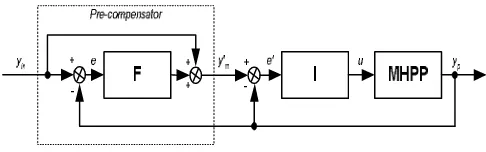
D.Fuzzy Pre-Compensated I C ontroller
Pre-compesated[8] of hybrid fuzzy I controller, was developed to combine the advantages of I controller and fuzzy pre-compesated fuzzy controller. The quantity e’(k) is the compenseted position error between the pre-compenseted position error input ym’(k) and MHPP output
yp(k), and ∆e(k) is the pre-compensanted position error. As shown in Figure 4 bellow .
Figure 4 : Block Diagram of Fuzzy Pre-compensated I controller.
D.Data Simulation of MHPP Plants
3 is done to adjust with the existing MHPP plant, detail as
shown in Table 1.
Table 1. Data plant MHPP simulation
No Data Value
1. Total rated capacity 5 Kw 2. Normal Operating Load 1 Kw
3. Inertia Constant H 7.75 seconds (2<H<8) 4. Regulation R 10 Hz/pu kW (2<R<10)
Assumption:[5],[9] Load-frequency dependency is linier. Nominal Load = 48%=0.48; ∆Pd =3%=0.03. The dumping parameter [4,7],
D = ∂p/∂
pukW
Hz
x
x
f
D
0
.
0016
/
5
60
1
48
.
0
p/
Generator parameters are: Kp = 1/D = 625 Hz/pu kW
Tp =
onds
xD
f
xH
sec
161,458
2
0
All data of gain parameter use for simulation controller I, PI, PID and Fuzzy-I shown in table 2
Table 2. Data gain simulation
Kp Ki Kd
I - -0.00003 -
PI 0.0555 -0.0021 -
PID 0.042156 -0.003253 0.0000246
Fuzzy I - 0.00075 -
III. FORMULATION OF PLANT MODELS FOR MHPPPLANT A. PI-PID Controller of Micro Hydro
` The block diagram of the MHPP[9] Plant with PID-Controller is shown in Figure 5. The PID-PID-Controller with the following transfer function is superimposed on the servomotor based governor as G(s)=Kp+Ki/s+Kd s, Where it’s Kp = proportional constant, Ki = integral constant and Kd = derivative constant.
Figure 5. Models of MHPP plant with PID-Controller
B. I-Fuzzy I Controller of MHPP
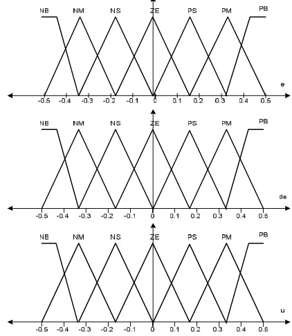
Control model MHPP with pre-compaseted Fuzzy[10],[11],[12],[13],[8] as in Figure 4, is made with blocks model transfer function can be simulated with Matlab. The block Fuzzy logic has a rule 28 with a combination of NB, NM, NS, ZE, PS, PM, PB with membership fucntion as shown in Figure 7.
NB : negative big; NM : negative medium; NS: negative small; ZE : zero; PS: positive small; PM : Positive Medium; PB: positive big
Figure 6. The Fuzzy sets of a pre-compensator Table 2. Fuzzy Rules of Pre-compensator
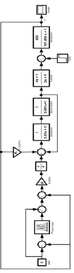
4 Figure 8. Blok diagram Models of MHPP plant using
fuzzyController
IV. SIMULATIONRESULT
Simulation Matlab of MHPP was run to use parameter table 1. Controller of MHPP was replaced by the controller of I, PI, PID and Fuzzy I. Simulation results show that for the I-controller the system stabilized at t = 300 seconds, with overshot between 0 - 0.1 Hz but the system never to the setting point = 0, a decrease of 0.003 Hz.
For the PI controller with Ki = -0.0021 and Kp = 0.0555 showed the system stable at t = 50 with overshoot about 0 to 1.2 Hz. System toward to the setting point 0 Hz. PID controller results with the parameters Ki = -0.003230, Kp and Kd = 0.042156 = 0.0000246 showed the system to be stable at t = 49 seconds with overshot between 0 to 1.1 Hz. System toward to the setting point 0 Hz .
Figure 10. Output ∆f of Integrator
Figure 11. Comperation error controller of Fuzzy I
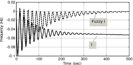
5 Figure 13. Comperation Output I and Fuzzy I
Comparison between I and Fuzzy-I controller indicates that the value of overshot is almost the same between 0.01 to -0.1 Hz. But with I-controller was system stable 100 seconds faster than the Fuzzy-I, but the system didn’t going to the reference point. While Fuzzy-I controller system stable at t = 400 seconds, but the advantage is directly to the setting point.
V. CONCLUSION
MHPP can be controlled with models controller I, PI, PID and Fuzzy-I. Parameters of gain control each controller will be found by with trial and error until is found the system stable. PID controller have the parameters Ki , Kp and Kd, to make a PI controller to eliminate the Kd parameters, but the value of Ki and Kp must be settings again. If making I-controller with to eliminate the parameters of Kp and a value of Ki but must be set back. MHPP plant system is stable with the controller I at Ki = -0.00004, with a PI controller is Ki = 0.0555 and Kp = -0.0021. While the system stable with PID controller is obtained at Ki = -0.003253, Kp and Kd = 0.042156 = 0.0000246.
To build the Fuzzy-I controller, the controller I, is added a pre-Compensator which setting directly by the 28 rule of fuzzy. The results obtained the Fuzzy-I controller was able to make the system MHPP stable at setting point and overshoot values relatively small compared with PI and PID.
ACKNOWLEDGMENT
This research was supported by (1). the Ministry of Culture and Education, under LPPM Udayana University, scheme Research
OF Unggulan Udayana BOPTN 2013 funding. Contract
number: 175A.4/UN14.2/PNL.01.03/2013, date 16 Mei 2013.
(2). Muhammad Abdillah from Hiroshima University, Japan that helps found a control modeling.
REFERENCES
[1] T. H. Ching, T. Ibrahim, F. I. A. Aziz, and N. M. Nor, “Renewable energy from UTP water supply,” in 2011 International Conference on Electrical, Control and Computer Engineering (INECCE), 2011, pp. 142 –147.
[2] T. Sakurai, H. Funato, and S. Ogasawara, “Fundamental characteristics of test facility for micro hydroelectric power generation system,” presented at the International Conference on Electrical Machines and Systems, 2009. ICEMS 2009, 2009, pp. 1 –6.
[3] T. Niimura and R. Yokoyama, “Water level control of small-scale hydro-generating units by fuzzy logic,” in , IEEE International Conference on Systems, Man and Cybernetics, 1995. Intelligent Systems for the 21st Century, 1995, vol. 3, pp. 2483–2487 vol.3.
[4] L. Jasa, P. Ardana, and I. N. Setiawan, “Usaha Mengatasi Krisis Energi Dengan Memanfaatkan Aliran Pangkung Sebagai Sumber Pembangkit Listrik Alternatif Bagi Masyarakat Dusun Gambuk –Pupuan-Tabanan,” in Proceding Seminar Nasional Teknologi Industri XV, ITS, Surabaya, 2011, pp. B0377–B0384.
[5] L. Jasa, A. Priyadi, and M. Hery P, “PID Control for Micro Hydro Power Plants Base on Neural Network,” in Proceding Modeling, Identification and Control (AsiaMIC 2012), Phuket, Thailand, 2012. [6] L. Jasa, A. Priyadi, and M. H. Purnomo, “Designing angle bowl of
turbine for Micro-hydro at tropical area,” in 2012 International Conference on Condition Monitoring and Diagnosis (CMD), 2012, pp. 882 –885.
[7] M. Djiteng, Pembangkitan Energi Listrik. Jakarta: Erlangga, 2005. [8] P. Pratumsuwan and C. Thongchaisuratkrul, “Pre-compensation for a
Hybrid Fuzzy PID Control of a Proportional Hydraulic System,”
www.Intechopen.com, pp. 202–218, Apr. 2011.
[9] M. Hanmandlu, H. Goyal, and D. P. Kothari, “An Advanced Control Scheme for Micro Hydro Power Plants,” in International Conference on Power Electronics, Drives and Energy Systems, 2006. PEDES ’06, 2006, pp. 1 –7.
[10] E. Özbay and M. T. Gençoğlu, “Load frequency control for small hydro power plants using adaptive fuzzy controller,” in 2010 IEEE International Conference on Systems Man and Cybernetics (SMC), 2010, pp. 4217–4223.
[11] B. Anand and A. E. Jeyakumar, “Load Frequency Control of Interconnected Hydro-Hydro System with Fuzzy Logic Controller,” in
2011 International Conference on Process Automation, Control and Computing (PACC), 2011, pp. 1–4.
[12] M. Abdolmaleki, P. Ansarimehr, and A. M. Ranjbar, “A robust fuzzy logic adaptive PI controller for hydro power plants,” in SICE, 2007 Annual Conference, 2007, pp. 2592–2595.