ISSN 0974-3154 Volume 6, Number 5 (2013), pp. 717-726 © International Research Publication House
http://www.irphouse.com
Review of Thrust Reverser Mechanism used in
Turbofan Jet Engine Aircraft
Mohd Anees Siddiqui1* and Md Shakibul Haq2
1
Department of Mechanical Engineering, University Polytechnic, Integral University, Lucknow, INDIA.
2
Department of Mechanical Engineering, University Polytechnic, Integral University Campus, Shahjahanpur, INDIA.
Abstract
Through this paper an initiative is taken to put focus on a special technique of thrust reverser mechanism which is common to the aviation industries but an uncommon in general. In this technique, forward thrust produced by jet engine of aircraft is diverged to reverse direction so as to provide an additional braking effect during landing and power back effect. This additional braking effect is responsible for reducing the landing run and other considerations related to safety of aircrafts. Different ways for thrust reverser i.e. Cascade type reverser system (cold stream), Clamshell door system (hot stream) and Bucket target system (hot stream) discussed. As Bucket target system has advantages over other systems of thrust reversal thus different mechanism of this type of thrust reversal are also discussed further. Keywords: Jet Engine, Thrust reverser, Bucket target.
1.
Introduction
friction brakes located on the gear. When thrust is reversed, passengers will hear a sudden increase in engine noise, particularly seated just forward of the engines [1].
Fig. 1: A KLM with reverse thrust buckets (left) [6] and Northwest DC9's used to pushback with reverse thrust "Power Back"(right). [7]
One common misconception about thrust reversing is that the engine itself actually runs in reverse, but this is not the case. In other words, air does not come in through the nozzle of the engine and be exhausted through the inlet to "reverse" the thrust. The engine itself still operates in the same manner, but the thrust it generates is redirected to produce drag.
Fig. 2: Different decelerating devices installed on current commercial aircrafts such as wheel brakes, spoilers and thrust reversers.
1.1 Requirement of thrust reverser mechanism
1.2 Advantages of Thrust Reverser Mechanism
As far as use of Thrust Reverser Mechanism is concerned, it has several advantages related to safety and other factors.
Fig. 3: Comparative landing runs with and without thrust reversal and it is seen that by using thrust reversers, landing is reduced up to an extent and this
effect is more in slippery and icy runways. [1]
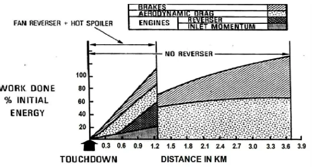
Fig. 4: Graph shows relation b/w work done and landing run with respect to use of thrust reversers in icy/wet runways, and it is seen that landing run is
reduced about 2.5 Kms. [3].
2.
Engine Power Reverse Thrust Characterstics [3]
Engine power reverse thrust characteristics can be drawn as per the rated rpm and % of rated Thrust, it is observed that Reverse thrust is max at higher speeds of Engine. So, Thrust reversers are more efficient at higher engine rpm.
Fig. 5: Graph for a turbofan engine of reverse thrust data versus engine power level for the reverser geometry of an embodiment of the bucket target type
thrust reverser in the deployed position.
3.
Different Thrust Reverser Types
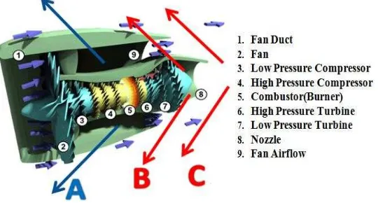
Fig. 6: Animated cross-section of jet engine showing different parts and arrows show ways of reversing thrust.[8] 3.1 Cascade type reverser system (cold stream)
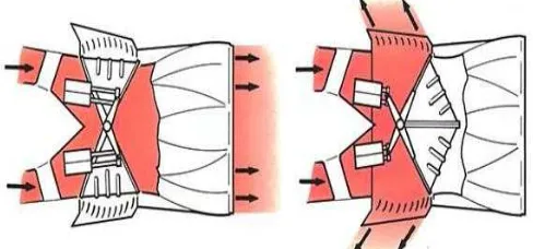
screw-jacks, or by a system using hydraulic rams. When the engine is operating in forward thrust, the cold stream final nozzle is ’open’ because the cascade vanes are internally covered by the blocker doors (flaps) and externally by the movable (translating) cowl; the latter item also serves to reduce drag. On selection of reverse thrust, the actuation system moves the translating cowl rearwards and at the same time folds the blocker doors to blank off the cold stream final nozzle, thus diverting the airflow through the cascade vanes.
Fig. 7: Cascade type thrust reverser system using cold fan stream for reverser of thrust of a jet engine.
3.2 Clamshell door system (hot stream)
The clamshell door system is a pneumatically operated system. On the selection of reverse thrust, the doors rotate to uncover the ducts and close the normal gas stream exit. Cascade vanes then direct the gas stream in a forward direction so that the jet thrust opposes the aircraft motion. The clamshell doors are operated by pneumatic rams through levers that give the maximum load to the doors in the forward thrust position; this ensures effective sealing at the door edges, so preventing gas leakage. The door bearing and operating linkage operate without lubrication at temperatures of up to 600 ºc.
3.3 Bucket target system (hot stream)
The bucket target system is hydraulically actuated and uses bucket-type doors to reverse the hot gas stream. The thrust reverser doors are actuated by means of a conventional pushrod system. A single hydraulic powered actuator is connected to a drive idler, actuating the doors through a pair of pushrods (one for each door). The reverser doors are kept in synchronization through the drive idler. The hydraulic actuator incorporates a mechanical lock in the stowed (actuator extended) position. In the forward thrust mode (stowed) the thrust reverser doors form the convergent-divergent final nozzle for the engine.
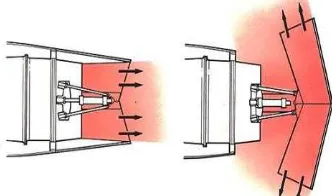
Fig. 9: Bucket target type thrust reverser system using deflector doors which are installed after nozzle of a jet engine.
As per the geometry of jet engine, maximum thrust is available only at the exit of nozzle. It is seen in bucket target type of thrust reverser mechanism is more efficient than other types because maximum amount of thrust which is coming out from jet engine is made to be reversed by using deflector doors at the back of jet engine.
4.
Types of Mechanisms for Bucket Target Type Thrust Reverser
As bucket target system is more efficient than other thrust reversal mechanism so further different patents, reports and other available literature related to bucket target type thrust reverser mechanism is reviewed further.
4.1 Pivot fairing thrust reverser
be suitably sealed to the exhaust nozzle when stowed for reducing or minimizing exhaust gas leakage through the convoluted perimeter of the doors. [3]
Fig. 10: Isometric view of an exemplary turbofan gas turbine aircraft engine having a thrust reverser mounted at the end in stowed (left) and deployed (right) [3] 4.2 Screw Jack Mechanism
This mechanism consist a pair of nested screw jacks commonly driven by a drive motor. The inner screw jack translates the blocker doors aft and the outer screw jack deploys the blocker doors into the engine jet stream. The first screw jack is operatively coupled to a translating support which translates either aft or forward, depending on the rotational direction of the first screw- jack to either deploy or stow the reverser doors. The translating support carries the reverser or blocker doors therewith. A second screw jack is mechanically connected to the first screw jack and rotates therewith. The second screw jack is connected through a translatable carriage and drive links to each reverser or blocker door. The slid able connection between the first and second screw jacks allows the second screw jack to translate relative to the first screw jack when rotated. The second screw jack has threads of a different pitch than those of the first screw jack. The thread pitch difference causes the reverser or blocker doors to translate aft at a speed at greater than the speed which they are rotated into or out of the engine gas steam thereby ensuring that the engine is not back pressured or overheated as the thrust reverser is deployed [4].
4.3 Fishmouth Thrust Reverser Nozzle
A thrust reverser nozzle for coaxial-flow turbofan engines comprising target-type deflector doors which are hinged for deployment about a fixed axis by means of actuation about single fixed pivots mounted on support structure on either side of the engine nacelle rearward portion. The deflector door's outer surfaces are shaped to match existing aerodynamic contours of the aircraft engine nacelle so as to provide a lower boattail angle for improved drag characteristics in the stowed or normal flight position. Geometry of the upstream portion of the inside surface of the doors is sized and shaped with end plates so that when the deflector doors move to the deployed position, the exhaust streams are diverted outward and forward to produce a desired level of reverse thrust [5].
Fig. 12: Section view of the embodiment of thrust reverser with the actuator mechanism and the deflector doors in stowed position (left) the
deployed position (right) [5].
5.
Conclusion
In the present scenario with the proper implementation of this technique of additional braking system more and more accidents can be avoided in adverse climatic conditions. This technique also shows how the energy that would go in vain would be utilized in such a positive manner. As per the geometry of jet engine, maximum thrust is available only at the exit of nozzle. It will be better to install reversers at the position where maximum forward thrust is available. It is seen in bucket target type of thrust reverser mechanism is more efficient than other types because maximum amount of thrust which is coming out from jet engine is made to be reversed by using deflector doors at the back of jet engine.
References
[1] The Jet Engine, Rolls-Royce (1996), Derby / England, PP-159-166.
Thrust Reversers on Commercial Transport Airplanes, Report- TM-109158, January 1995.
[3] Rodger L. Modglin, Frederick H. Peters, U.S. Patent (6,487,845 B1), Pivot Fairing Thrust Reverser, Cleveland, Tulsa, Dec 2002.
[4] Richard H. Timms, U.S. Patent (4,519,561), Aircraft Thrust Reverser Mechanism, San Diego County, Calif, May 1985.
[5] William K. Great house U.S. Patent (4147027), Thrust Reverser Nozzle, East Northport, N.Y, April 1979
[6] The Wikipedia website. Available:
http://en.wikipedia.org/wiki/Thrust_reversal
[7] The DTW website. Available: http://dtw.natca.org/photos.htm [8] Turbofan Labelled.gif. Available:
![Fig. 1 : A KLM with reverse thrust buckets (left) [6] and Northwest DC9's used to pushback with reverse thrust "Power Back"(right)](https://thumb-ap.123doks.com/thumbv2/123dok/3193284.1736155/2.595.148.470.444.544/reverse-thrust-buckets-northwest-pushback-reverse-thrust-power.webp)
![Fig. 10 : Isometric view of an exemplary turbofan gas turbine aircraft engine having a thrust reverser mounted at the end in stowed (left) and deployed (right) [3]](https://thumb-ap.123doks.com/thumbv2/123dok/3193284.1736155/7.595.191.408.577.683/isometric-exemplary-turbofan-turbine-aircraft-reverser-mounted-deployed.webp)
![Fig. 12 : Section view of the embodiment of thrust reverser with the actuator mechanism and the deflector doors in stowed position (left) the deployed position (right) [5]](https://thumb-ap.123doks.com/thumbv2/123dok/3193284.1736155/8.595.190.399.300.401/section-embodiment-reverser-actuator-mechanism-deflector-position-deployed.webp)
