TRANSFERRING MULTI-SCALE APPROACHES FROM 3D CITY MODELING
TO IFC-BASED TUNNEL MODELING
A. Borrmann
a,*, T. H. Kolbe
b, A. Donaubauer
b, H. Steuer
b, J. R. Jubierre
aa
Chair of Computational Modeling and Simulation, Technische Universität München, Germany - (andre.borrmann, javier.jubierre)@tum.de
b
Chair of Geoinformatics, Technische Universität München, Germany - {thomas.kolbe, andreas.donaubauer, steuer}@tum.de
Commission II, WG II/2
KEY WORDS: Multi-scale representation, Levels of Detail, CityGML, Building Information Modeling
ABSTRACT:
A multi-scale representation of the built environment is required to provide information with the adequate level of detail (LoD) for different use cases and objectives. This applies not only to the visualization of city and building models, but in particular to their use in the context of planning and analysis tasks. While in the field of Geographic Information Systems, the handling of multi-scale representations is well established and understood, no formal approaches for incorporating multi-scale methods exist in the field of Building Information Modeling (BIM) so far. However, these concepts are much needed to better support highly dynamic planning processes that make use of very rough information about the facility under design in the early stages and provide increasingly detailed and fine-grained information in later stages. To meet these demands, this paper presents a comprehensive concept for incorporating multi-scale representations with infrastructural building information models, with a particular focus on the representation of shield tunnels. Based on a detailed analysis of the data modeling methods used in CityGML for capturing multi-scale representations and the requirements present in the context of infrastructure planning projects, we discuss potential extensions to the BIM data model Industry Foundation Classes (IFC). Particular emphasis is put on providing means for preserving the consistency of the representation across the different Levels-of-Detail (LoD). To this end we make use of a procedural geometry description which makes it possible to define explicit dependencies between geometric entities on different LoDs. The modification of an object on a coarse level consequently results in an automated update of all dependent objects on the finer levels. Finally we discuss the transformation of the IFC-based multi-scale tunnel model into a CityGML compliant tunnel representation.
* Corresponding author.
1. INTRODUCTION
Since their existence, geographic maps rely on the concept of scale-dependent representations for providing cartographic information on a suitable level of abstraction. This helps to reduce the complexity of the maps’ content, improves their readability and allows the viewer to concentrate on the relevant information. This approach has consequently been adopted by digital cartographic methods and integrated into the respective data models and standards. For example, CityGML, a comprehensive data model for representing 3D city models, provides five different levels-of-detail (Kolbe 2008) to meet the demands of different application scenarios.
Construction planning also relies heavily on the use of different scales for representing geometric information on a suitable level of detail. The produced drawings range from general site layout plans, which provide an overview of the entire project, down to detailed workshop drawings presenting the precise design of individual components, connection points etc.
Employing a multi-scale representation is particularly important in the context of planning carriageway projects. Here, strongly differing scales have to be considered – ranging from the kilometre scale for the general routing of the carriageway down to the centimetre scale for the detailed planning of individual
track nodes. Despite the multi-scale characteristics inherent to the planning of carriageways, today’s data models for representing and exchanging planning data support multi-scale modeling only to a very limited extent.
Another important aspect of modern computer-aided track planning is the increasing demand for integrating computer-aided design (CAD) with geographic information systems (GIS). While the former is required to perform the actual design process, the latter is used for assessing the resulting track design with respect to different criteria, such as environmental impact, traffic connections etc. This concept – which is often referred to as “geo-design” – has received increased attention in recent years (Steinitz 2012).
In this paper we describe an approach for transferring the concept of multi-scale representations from the field of 3D city modeling to the field of infrastructure planning, more precisely the planning of tunneled carriageways. A major challenge lies in the diverging characteristics of the application scenarios with respect to the data dynamics. While geographic and cartographic information is rather static and rarely subject to modifications, the design process involved with the planning of carriageways is highly dynamic and data updates occur in high frequency. The conventional approach taken by geographic data models, which relies on maintaining independent
ISPRS Annals of the Photogrammetry, Remote Sensing and Spatial Information Sciences,
representations on the different levels-of-detail, is thus not appropriate here, as the risk of losing consistency is too high. To overcome this issue, we are proposing an approach which is based on the explicit modeling of dependencies between the individual levels of detail to achieve automated consistency preservation. This is realized by means of a procedural description of the geometric model, i.e. the geometry is not described through an explicit boundary representation but by means of a procedural description comprising the individual construction steps conducted. In addition, methods of parametric modeling are employed to define dependencies between the geometric entities of the different levels of detail. Modifying the representation on a coarse LoD thus results in an automated update of all dependent objects on the finer LoDs – hence realizing automated cross-LoD consistency preservation.
An important objective of our multi-scale data modeling activities is the maintenance of spatio-semantic coherence (Stadler & Kolbe 2007; Clementini 2010): The semantic description must be aligned with the geometric representation. We discuss in detail how this aspect is addressed in the proposed multi-scale model.
For the purpose of GIS-based route assessment, its visualization in a geographical context, or the continuation of the spatial database after completion of the planned object, the procedurally created model has to be embedded in the geographic context. In order to achieve this, the semantic and geometric data of the model needs to be transformed into an explicit representation, e.g. into the CityGML format. We also discuss this aspect.
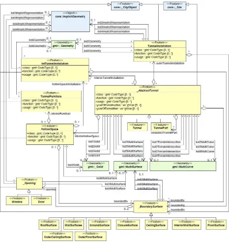
The paper is organized as follows: Section 2 gives an overview on the multi-scale facilities of the geospatial standard Figure 1. The CityGML data model for the multi-scale representation of tunnels (Source: (Gröger et al. 2012))
ISPRS Annals of the Photogrammetry, Remote Sensing and Spatial Information Sciences,
CityGML, in particular with respect to the modeling of tunnels. Section 3 describes the concepts and techniques of parametric and procedural modeling which provide the basis for dynamic multi-scale modeling with automated cross-LoD consistency preservation. Based on this, Section 4 presents an IFC-based multi-scale product model for shield tunnels and discusses its integration with a procedural geometry representation. Section 5 describes the mapping of the product model to the geospatial model CityGML. Section 6 concludes the paper and summarizes its main findings.
2. MULTI-SCALE MODELING OF TUNNELS IN
CITYGML
Multi-scale modeling is an integral part of the CityGML standard and is implemented through five well-defined Levels of Detail (LoD). This concept makes it possible for an object to be represented in different LoDs simultaneously. In this way results from differing data collection methods or models optimized according to differing application requirements can be integrated in a single dataset (Kolbe & Gröger 2003). Additionally, LoDs enable efficient data analysis and visualization.
CityGML supports a concept of cartographic generalization (where a set of objects which are too small to visualize on a specific scale is aggregated into a joint representation
(McMaster & Shea 1992)) by providing an explicit generalization association between city objects. For example, several city objects of a high level of detail may be represented by a single object on a lower level of detail.
Since in this paper we are focusing on the representation of tunnel constructions, we will discuss the LoD features by means of the tunnel model which has been introduced to CityGML since version 2.0 (Gröger et al. 2012).
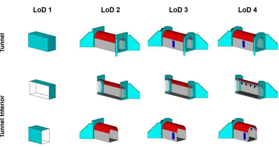
On each of the LoDs 1-4, a tunnel object can be represented by distinct geometries. Since CityGML employs a consistent LoD concept for all its thematic modules, the LoDs 1-3 describe the outer shell only; more precisely the tunnel’s boundary surface adjacent to the surroundings. LoD 4 adds the modeling of the interior of a tunnel.
Figure 1 depicts the data model in UML notation while Figure 2 illustrates the geometric-semantic representations of a tunnel on different LoDs.
A tunnel model in LoD 1 consists of a boundary representation of the tunnel volume without any further semantic classification. Its geometry must be a solid resulting from a vertical extrusion. Additionally it is possible to model the intersection of tunnel and terrain using gml::MultiCurve. In LoD 2 a tunnel may be modeled in greater detail using additional gml::MultiSurfaces or gml::MultiCurves. Additionally, the structure of a tunnel can be differentiated semantically.
Figure 2. Illustration of the geometric representation of tunnels on different LoDs (Source: (Gröger et al. 2012))
ISPRS Annals of the Photogrammetry, Remote Sensing and Spatial Information Sciences,
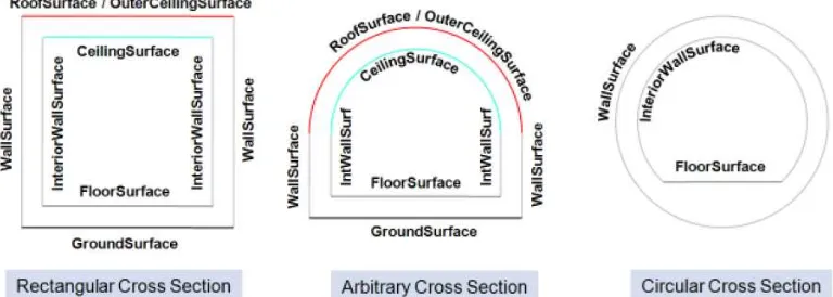
Thus, boundary surfaces can be classified as wall, roof, ground plate, outer floor, outer ceiling or ClosureSurfaces (for examples see Figure 3). Furthermore, tunnel elements which strongly affect the outer appearance, e.g. stairs, can be modeled using the class TunnelInstallation which is additionally described by its attributes class, function and usage.
LoD 3 adds openings like doors and windows represented as thematic objects to the tunnel model.
LoD 4 provides the most detailed modeling capabilities by allowing the modeling of the interior structure of a tunnel. The free space inside of a tunnel can be subdivided into several (potentially overlapping) semantic objects called HollowSpace. According to the CityGML standard a HollowSpace “should be uniquely related to exactly one tunnel or tunnel part object” (Gröger et al. 2012). It may be classified by its attributes class, function and usage where class denotes a general classification, e.g. commercial or private rooms, and function and usage describe the designated and actual usage respectively.
Using the grouping concept provided by CityGML, hollow spaces may be aggregated according to arbitrary, user defined criteria. These groups can be semantically enriched by providing group names, specific attributes and role names of the participating objects.
The boundary surfaces of a HollowSpace may be modeled as specialized, semantic objects like FloorSurface, CeilingSurface, InteriorWallSurface, and ClosureSurface (see Figure 3). Furthermore, interior objects which cannot be moved can be represented in LoD 4 by the class IntTunnelInstallation. Tunnel Installations can either be associated with HollowSpaces (e.g. ventilator, signals) or with the _AbstractTunnel (e.g. pipes or cable trench).
However, the standard states that “it will be within the responsibility of the user or application to make sure objects in different LoDs refer to the same real-world object” (Gröger et al. 2012). This implies furthermore that the consistency of representations of objects on differing LoDs has to be ensured by the user or application.
The multi-scale modeling approach of tunnels in CityGML has two major limitations in the context of the planning of tunneled carriageways:
A single object can be represented by differing, disjointed geometric representations on the different LoDs. The
consistency of these differing representations cannot be ensured by CityGML.
For the planning process of a tunnel, a LoD model of the interior is needed. In CityGML the interior is modeled only on LoD 4.
To sum up, a more specialized LoD approach is needed for the highly dynamic phases of planning processes. In the following sections we present an approach which helps to ensure the consistency of representations on different LoDs.
3. MULTI-SCALE GEOMETRIC MODELING FOR
DYNAMIC PLANNING PROCESSES
3.1 Overview
This paper presents a new methodology for creating and storing multi-scale geometric models for infrastructure projects which relies on the explicit definition of dependencies between the individual levels-of-detail. These explicit dependencies allow for automated consistency checks and even automated consistency preservation. The methodology relies on parametric modeling technologies (Shah & Mäntylä 1995), including the use of dimensional and geometric constraints for defining flexible 2D sketches, as well as the procedural definition of complex 3D models through the sequential use of geometric operations such as extrusion, transformation and Boolean operations.
Parametric modeling techniques facilitate a step-wise development of infrastructure models evolving from a coarse level of detail to the finer ones, which precisely reflects the well-established best practice in infrastructure planning. Conventionally, fundamental modifications on a coarse level in a late planning phase, such as the modification of the principal tunnel axis, force the planners to completely re-elaborate all related models and plans, e.g. the detailed tunnel geometry. Applying the methodology presented in this paper ensures that modifications on a coarse LoD are automatically propagated to all finer LoDs, thus providing a means for the automated preservation of consistency and, at the same time, significantly reducing the effort required for re-elaboration.
Figure 3. Examples of semantic objects for boundary surfaces in tunnels. In LoD2-4 only the outer surfaces (WallSurface, RoofSurface, GroundSurface, OuterCeilingSurface and OuterFloorSurface) are available while the interior surfaces (InteriorWallSurface, FloorSurface and CeilingSurface) may only be used in LoD 4 (Excerpt from (Gröger et al. 2012))
ISPRS Annals of the Photogrammetry, Remote Sensing and Spatial Information Sciences,
3.2 Procedural model-based methodology for consistency preservation in multi-scale models
The proposed methodology for the creation and management of multi-scale geometric models relies on an explicit definition of dependencies between the individual levels-of-detail. These explicitly available dependencies allow for an automatized preservation of the consistency of the multi-scale model. The definition of the dependencies is realized by applying technologies provided by parametric CAD systems. The core concept is not to store the final outcome of the construction process, i.e. an explicit geometric model, but instead the history of the individual construction operations. Such models, which are referred to as procedural models or construction history models, combine the use of dimensional and geometric constraints for defining flexible 2D sketches, with the concept of a procedural definition of complex 3D models through the subsequent use of geometric operations such as extrusion, rotation and Boolean operations (Mun et al. 2003, Stiteler 2004, Pratt et al. 2005, 2010, Koch & Firmenich 2011). Parametric modeling concepts have recently been applied to create highly flexible and adaptable models of infrastructure facilities, such
as bridges and roadways (Ji et al. 2010, Ji et al. 2011, Obergriesser et al. 2011, Ji et al. 2013).
These techniques facilitate a step-wise development of the infrastructure model evolving from a coarse level of detail to the finer ones. In the proposed concept, the LoDs can be flexibly defined by the planning team according to the requirements of the infrastructure project under consideration. During the modeling process, switches between one LoD and another are explicitly triggered by the designing engineer who in this way decides which geometric elements belong to which LoD.
Applying procedural technologies for multi-scale modeling provides the possibility for a stringent definition of dependencies between individual geometric elements on different levels of detail. Thus the levels-of-detail of the model are not isolated from each other, but inter-related by means of the construction history. Accordingly, the resulting multi-scale model is inherently consistent and preserves a high degree of flexibility. Modifications of elements of a coarse LoD, such as the principal axis of the tunnel are automatically propagated to all dependent objects on the finer LoDs.
Semantics
Geometric Representation
Figure 4. Separation of geometry and semantics in the IFC data model; different geometry representations provided by the IFC
Physical Objects
(instances of subclasses of TunnelElement)
Space Objects
Tunnel Envelope
AnnularGapSpace
LiningSpace
InteriorSpace
Clearance Space
Service Space
Floor Space Service Space
Track Space Clearance Space
Traffic Light
Cable Duct
Drainage
Trackbed Concrete Segment
Walkway
Floor Concrete Rail System
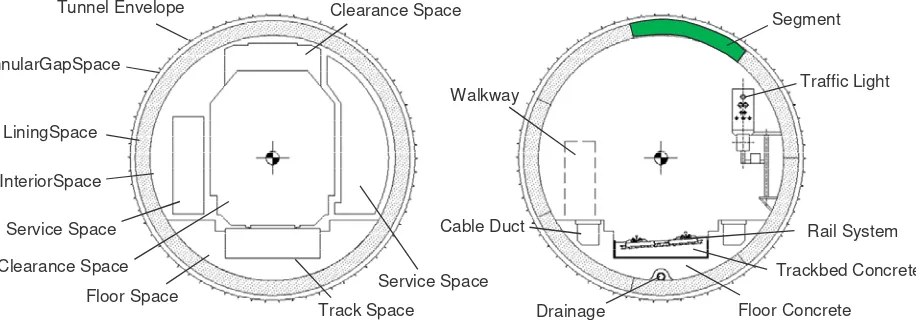
Figure 5. A tunnel cross-section showing the individual spaces (left) and elements (right) of the product model
ISPRS Annals of the Photogrammetry, Remote Sensing and Spatial Information Sciences,
However, there are limits to the degree of modifications on coarse levels which can be propagated to finer ones. These limits are mainly driven by operations in the construction history which only produce results if certain conditions are fulfilled by their operands. A typical example is the Boolean intersect operation which only generates a valid volume object if the operands do overlap. If their position is determined by earlier operations, the Boolean operation might fail, resulting in a non-evaluable procedural model.
For more information on the use of procedural for creating inherently consistent multi-scale models, the reader is referred to (Borrmann et al. 2012a, b), (Borrmann & Jubierre 2013).
4. A MULTI-SCALE SHIELD-TUNNEL PRODUCT
MODEL
4.1 Overview
Within the AEC industry, the data exchange between different stakeholders is of crucial importance. The use of neutral, open data formats has proven to be the most suitable approach to realize this data exchange. Here we aim to provide a neutral
data model which provides the possibility to share a procedural description of multi-scale models in order to transmit the dependencies between the different LoDs and which makes it possible to maintain the flexibility and inherent consistency of the model.
For supporting data exchange in the domain of building design, engineering and construction, the comprehensive data model Industry Foundation Classes (IFC) has been developed over the last decade. As opposed to the CityGML standard, the IFC are not defined as an UML or XML schema. Instead the model is specified using the data modeling language EXPRESS1, which forms part of the ISO standard 10303 “STEP – Standard for the exchange of product modeling data”. Other import particularities of the IFC model are the comprehensive use of objectified relationships and inverse attributes (Eastman 1999). The model is very fine-grained and provides more than 600 entities for the detailed description of the semantics and the geometry of buildings and building components.
Only a few researchers have addressed the extension of the IFC model to also cover tunnel facilities. The most important contributions are those by Yabuki et al. who propose an IFC-based model for the description of shield tunnels (Yabuki et al. 2007, Yabuki 2009). However, so far they have not been adopted by official IFC standardization activities.
The main purpose of the IFC model is to support data exchange between different building design and engineering applications, in particular the seamless integration of various simulation and analysis tools. For this reason, large parts of the IFC standard are dedicated to extensive geometry representation capabilities, including different versions of Boundary Representation (BRep), Constructive Solid Geometry (CSG) as well as extrusion and sweep based geometry descriptions.
1
Though EXPRESS provides its own graphical notation for visualizing data models, we rely on UML for this purpose throughout the paper in order to facilitate access for non-experts.
IfcBuildingPart IfcProject IfcSite
IfcBuilding
IfcRelAggregates
IfcRelAggregates
IfcRelAggregates
*
*
*
1
1
1
Figure 6. Modeling of spatial structures in IFC
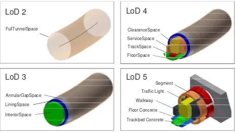
InteriorSpace LiningSpace FullTunnelSpace
LoD 2
LoD 3
AnnularGapSpace
LoD 4
LoD 5
ClearanceSpaceTrackSpace ServiceSpace
FloorSpace
Traffic Light
Trackbed Concrete Segment
Walkway
Floor Concrete
Figure 7. A 3D representation of the different LoDs of the multi-scale shield tunnel product model
ISPRS Annals of the Photogrammetry, Remote Sensing and Spatial Information Sciences,
Like the CityGML model, the IFC data model implements the important principle of a strict separation between the semantic description of the building (space objects, building elements, and their relationships) and its geometric description (Figure 4). Thus, a semantic object can be associated with multiple geometric representations (2D, 3D, BRep, CSG, etc.). This would, in principle, facilitate multi-scale modeling providing different levels-of-detail in the geometric part. However, the integration of the multi-scale concept in the semantic part and the explicit definition of refinement relationships is lacking so far.
For these reasons the current IFC model allows only very limited support for multi-scale modeling. However, as discussed earlier, multi-scale approaches are much needed to properly support the design and engineering of track-based infrastructure facilities, such as tunnels. To overcome this issue, we present a comprehensive approach for soundly integrating multi-scale modeling into an IFC-based infrastructure model. We follow the principle of “minimal intervention”, i.e. only minimal modifications and extensions to the existing data model are proposed. Our approach respects the important boundary condition that applications which do not support multi-scale approaches should also be able to access and display the model correctly.
We discuss our approach by extending a product model for shield tunnels, i.e. tunnels which are built by means of Tunnel Boring Machines (TBM), by multi-scale capabilities. However, the presented approach is general and can be applied to other linear infrastructure facilities in the same manner.
4.2 Semantic model
Based on preliminary work by (Yakubi et al. 2007) we are presenting a product model for shield tunnels which fulfills the demands of data exchange in the context of the design and engineering of large infrastructure projects. Like the IFC model, the proposed tunnel product model provides a clear separation
between semantic objects and the associated geometry. The integration of the semantic model with the procedural geometry description will be discussed in Section 4.3. In this section we focus on realizing the multi-scale approach for the semantic part. In the presented concept, the semantic entities are associated with a particular LoD, which helps to achieve and maintain the semantic-geometric coherence of the overall model (Stadler & Kolbe 2007; Clementini 2010).
Figure 5 depicts the main components of the tunnel model as 2D cross-sections, while Figure 7 provides a number of 3D views depicting the different LoDs.
In order to maintain downwards compatibility with the current IFC standard, we make extensive use of the space structure concept provided by the IFC to model refinement relationships across the LoDs. In the IFC standard, the concept is applied to provide a hierarchical aggregation structure for buildings, using
Site, Building, BuildingPart and BuildingStorey objects and organizing them by means of the relationship Aggregates
(Figure 6). As explained in detail below, we make use of the space structure concept for modeling cross-LoD refinement relationships.
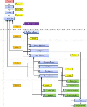
Figure 8 depicts how these objects are modeled and used in the proposed multi-scale tunnel model. The figure provides an instance diagram illustrating the implementation of the multi-scale concept. Figure 9 depicts the corresponding class diagram. In alignment with the IFC model, the proposed tunnel models consist of space objects (depicted in blue) and physical objects (depicted in green).
In order to group and provide access to all elements at a certain level of detail, we make use of a new class of relationship objects, which we name LoD. These objects aggregate all spatial and physical objects at the corresponding level. At the same time, we maintain the aggregation relationships across the different LoDs in order to explicitly model a refinement hierarchy. This is realized by the newly introduced relationship class Refines, a subclass of Aggregates.
ISPRS Annals of the Photogrammetry, Remote Sensing and Spatial Information Sciences,
One of the key aspects of our approach is that the refinement hierarchy is created with the help of space objects, while physical objects form part of the finest level only. This allows us to use spaces as placeholders on coarser levels, thus avoiding overlapping physical objects (which could be erroneously interpreted as clashes) and hence providing full compliance with the standard IFC approach. This is different from the LoD-model of CityGML where on each level physical objects can be described.
On LoD 1, the tunnel is represented geometrically by a line representing the main axis. To this end, the tunnel object is associated with an Axis object which in turn refers to the underlying alignment. Since the alignment plays a key role in the design and engineering of tunnels, it is essential to provide the genuine alignment objects such as lines, arc segments and clothoids as part of the product model.
For the levels 2 to 5 we make use of what we call the Matyroshka principle. In analogy to the Russian dolls, the
spaces on a finer level are fully included in a space provided by the coarser level. Physical objects are present only on the finest level, LoD 5.
Except for the ring space, all space objects represent longitudinal spaces along the entire TunnelPart. The Ring
space, however, has the length of a single ring segment only. The relations between the semantic objects rely on the space structure concept, modeling aggregation relationships between the site, the tunnel, the tunnel parts, the longitudinal spaces, and the rings.
On LoD 2, the space object TunnelFullSpace is used to provide a semantic object representing the entirety of the tunnel. This space object is further refined on LoD 3 by three distinct (non-overlapping) space objects: AnnularGapSpace, LiningSpace
and InteriorSpace. On LoD 4, the interior space is refined by the space objects ClearanceSpace, FloorSpace, TrackSpace and
ServiceSpace.
LoD 5 provides the physical objects of the tunnel model. All
Product LoD
Figure 9. UML class diagram depicting the introduced relationship classes Refines and LoD, as well as the classes TunnelSpace and TunnelInstallation which are used to model tunnel-specific spaces and installations. Classes depicted in blue are subclasses of SpatialStructureElement, classes depicted in green are subclasses of Element and represent physical objects. Relationship classes are depicted in yellow.
TunnelAxis
Figure 8. UML instance diagram showing the semantic part of the proposed shield tunnel product model incorporating a multi-scale representation. The TunnelPart object is associated with the different representations via dedicated LoD objects. The proposed tunnel models consists of space objects (depicted in blue) and physical objects (depicted in green). Refinement relationships are explicitly modeled across the LoDs. Implementing the Matyroshka principle, the spaces on a finer level are fully included in the corresponding space on the coarser level. Physical objects are modeled only on the finest level.
ISPRS Annals of the Photogrammetry, Remote Sensing and Spatial Information Sciences,
physical objects are assigned to a respective space via the
ContainedInSpatialStructure relationship: The objects
TrackBedConcrete and TrackBedRails belong to the
TrackBedSpace, CableDuct and Drainage belong to the
FloorSpace, and TrafficLight and Walkway objects are embedded in the ServiceSpace.
In addition, the LiningSpace defined on LoD 3 is refined into a number of Ring space objects on LoD 5. Ring space objects belong to the finest level of detail, since their definition happens at a very advanced stage of the planning process. Each
Ring space contains the RingSegments it is comprised of. In compliance with the principles of object-oriented modeling in general and the IFC modeling guidelines in particular, we decided against a fine-grained class structure where each and every space or component type is represented by a class of its own. Instead we make use of more general classes and provide them with a type attribute representing a pre-defined enumeration. This allows for easy maintenance and extendibility.
Following this paradigm we model the diverse spaces depicted in Figure 8, not as individual classes but subsumed by the class
TunnelSpace which in turn provides a type attribute to select from a number of pre-defined space types (FullTunnelSpace,
InteriorSpace, etc.). The same approach is applied to the physical tunnel objects which are subsumed by the class
TunnelInstallation. Here the type attribute is used to select from pre-defined element types (TrackbedConcrete, CableDuct etc.). Only RingSegment is modeled by means of a dedicated class due to its importance and particular characteristics. Consequently, the entities depicted have to be interpreted as instances of TunnelSpace or TunnelElement, respectively, and not as instances of specific classes.
Figure 9 also illustrates the introduction of the level of detail concept into the class model. Firstly, a dedicated relationship class LoD has been integrated as a subclass of the existing relationship class Aggregates. This relationship is used to relate instances of subclasses of Product to a given level of detail as illustrated in Figure 8. Secondly, the relations class Refines has been integrated for modeling the refinement relationships as shown in Figure 8.
As described in Section 3, an important part of our multi-scale concept for dynamic modeling processes relies on the use of a procedural geometry description in order to explicitly define dependencies between the geometric entities on the individual levels of detail and thus facilitate automated updating in the case of modifications. The integration of the procedural geometry with the model is described in the next section.
4.3 Procedural Geometry Description
For capturing a procedural model as described in Section 3.2, we developed a dedicated data model which consists of two main parts. The first part provides the possibility to describe parametric sketches which include geometric elements as well as the applied dimensional and geometrical constraints. This part has been published in (Ji et al. 2011). The second part enables the storing of the construction history of the geometric model.
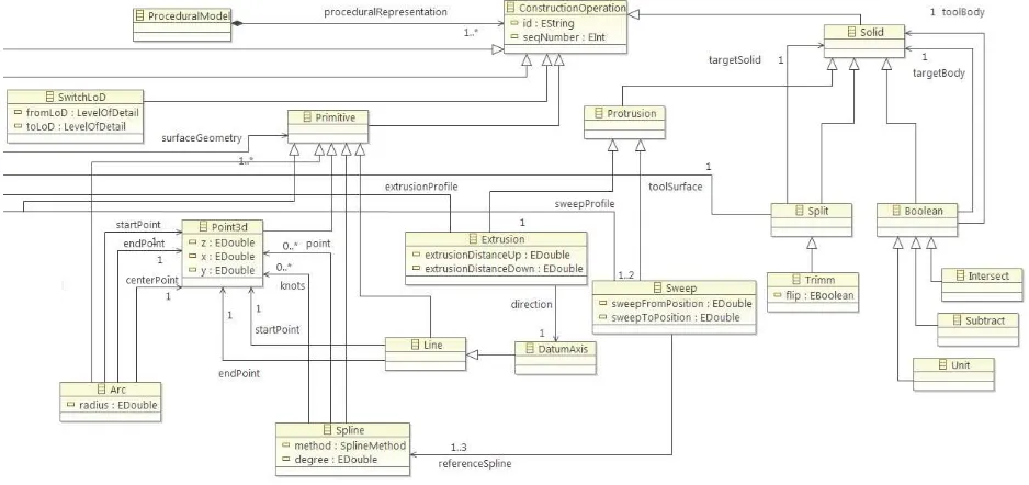
Figure 10 shows a section of the data model developed. The Procedural Model consists of an ordered list of Construction Operations. For Construction Operation there are a number of defined subclasses, among others Primitive, Sketch, and Solid. Primitive objects are Points, Lines, Splines and Arcs, for example. A Sketch object comprises primitive objects as well as dimensional and geometric constraints. Solid is the superclass of all operations which generate or modify a solid, such as the different protrusions, the Boolean operations, or specific split operations. Protrusion is subclassed by Extrusion and Sweep. Both operations take a sketch as the first argument, while
Extrusion uses a simple direction for the second argument, and
Sweep uses a spline as the extrusion path. In both case, the third argument is the protrusion distance.
Using these classes the most important parts of a procedural model can be captured. However not all construction operations provided by modern feature-based CAD systems are included. This applies to more specific construction operations such as chamfering, for example. This is due to the fact that those operations are of minor importance in infrastructure design, as opposed to the design in mechanical engineering.
By defining references from one procedural operation to
Figure 10. Section of the developed data model for capturing a procedural model (UML class diagram)
ISPRS Annals of the Photogrammetry, Remote Sensing and Spatial Information Sciences,
another (e.g. from the extrusion operation to the extrusion path), the dependencies between the geometric entities in the resulting procedural model are explicitly modeled. This makes it possible to realize the automated update mechanism described in detail in Section 3.2.
4.4 Integrating the semantic model with the procedural geometry description
To realize a coherent multi-scale product model, the multi-scale semantic model presented in Section 4.3 has to be properly integrated with the procedural geometry description introduced above.
For the geometry representation of the individual elements (spaces and physical objects), a procedural description is used. The individual operations of the procedural description can refer to operations or geometric entities used on lower levels. One example is the tunnel axis which acts as the LoD 1 representation: the assigned curve is used as the path for creating the extrusion geometry of all longitudinal objects on the finer LoDs. Another example is the sketch-based creation of space profiles on finer levels from coarser ones using offset operations applied to the sketch elements.
5. GEOMETRIC AND SEMANTIC MAPPING
BETWEEN THE IFC-BASED MULTI-SCALE MODEL AND CITYGML
In several phases of the planning process, it is necessary to integrate the 3D planning model into its geographic context, the latter being provided by a Geographic Information Systems (GIS). Examples are visualizing the model for the purpose of stakeholder involvement, environmental impact studies, testing collisions with existing infrastructure and updating a topographic information system after the completion of the structure. Integrating the 3D model created by a parametric CAD system into a GIS means to transform both the geometry and the semantics into a data structure which can be interpreted by a GIS. We show that this transformation is feasible using CityGML as the GIS data structure.
On the one hand, the procedural geometry model has to be transformed into an explicit (B-Rep) representation. This is due to the fact that geometry models following the generative modeling paradigm as it is applied by our procedural geometry model, are not supported by GIS or spatial database management systems due to various well-known reasons (cf. Kolbe, Plümer 2004), e.g. the lack of spatial indexes for geometries of such kind. The transformation can be carried out using modeling kernels like Parasolid or OpenCASCADE. On the other hand, a semantic transformation between our product model for shield tunnels and the respective concepts provided by CityGML must be carried out. The following table
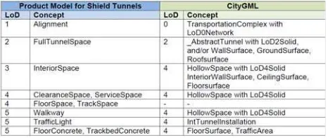
describes a semantic mapping between the concepts of the IFC-based product model and CityGML for the different LoD definitions.
Figure 11 shows that concepts from LoD3-5 from the product model are mapped to CityGML LoD 4 concepts. Although CityGML permits the modeling of free space inside a tunnel using the HollowSpace concept, only those types of space concepts from the product model are mapped to CityGML which are not occupied by physical objects. Therefore the
ClearanceSpace and ServiceSpace is mapped whereas the
FloorSpace and the TrackSpace are not. In some cases, the geometry types have to be changed from solids into multi-surfaces, e.g. when transforming an InteriorSpace object into
InteriorWallSurface objects. In other cases only parts of the geometry can be mapped, e.g. the surface of FloorConcrete and
TrackbedConcrete is mapped to FloorSurface. LoD3 is not relevant as the product model currently does not allow for specifying openings in the outer shell of the tunnel.
Since a more differentiated level of detail concept for indoor environments is under discussion for the next version of CityGML, it may be possible in future to also map FloorSpace
and TrackSpace.
Multi-scale representations are well established in geography and cartography. The underlying concepts have been adopted in the development of the corresponding digital data models. Among them is CityGML, the standard for representing 3D city models, which provides five dedicated levels-of-detail (LoD). Also digital representations of buildings, so-called building information models, can benefit significantly from storing and exchanging semantic and geometric in formation on different levels of detail. However, the introduction of multi-scale concepts into Building Information Models requires careful consideration of the highly dynamic planning processes which result in frequent modifications of the data stored in the BIM. The approach implemented by CityGML, which relies on storing an independent representation for each LoD, is not applicable here, since it bears the high risk of introducing inconsistencies when modifications are not simultaneously performed for all LoDs.
The paper has presented a methodology which enables the creation of multi-scale models where the individual levels of detail are inherently consistent with one another. The core concept is the definition of dependencies between geometry objects on different LoDs by making use of procedural geometry representations. The implementation of the concept is based on the application of parametric modeling techniques. Applications that are capable of interpreting and processing procedural geometry are able to automatically preserve the consistency of the multi-scale model by propagating changes on geometric objects to all dependent representations and updating them accordingly.
To illustrate the integration of this concept with an IFC-based data model we discussed the development of a multi-scale product model for shield tunnels. The semantic part of the model implements the multi-scale approach by providing explicit LoD objects and making use of the space aggregation hierarchy for modeling refinement relationships (the Matyroshka principle). The geometric part associates the individual semantic objects with a procedural description which is defined across multiple LoDs. The resulting product model provides geometric-semantic coherence and at the same time mechanisms for automated consistency preservation. It thus responds to the particular demands of multi-scale representations in the context of highly dynamic planning processes.
Figure 11. Semantic mapping between the product model for shield tunnels and CityGML
ISPRS Annals of the Photogrammetry, Remote Sensing and Spatial Information Sciences,
In a modern planning process it is desirable to closely interlink planning and impact analysis. This way, the drafted model can be analyzed in the context of its spatial environment, e.g. in an existing 3D city model, in order to study the environmental impact or to test collisions with existing infrastructure. Therefore, it is necessary to convert the procedural model into an explicit representation (B-Rep with absolute world coordinates), preferably in an automatic way and under preservation of the geometric and semantic information. While the geometric conversion can be achieved using geometric modeling kernels, the semantic mapping of concepts introduced within the product model to CityGML has been investigated in this paper. We have shown that most of the semantic concepts can be mapped, making it possible to use CityGML to integrate the tunnel design model with the environment model within one consistent framework.
An open question not tackled so far is the possibility to propagate modifications on finer LoDs to coarser ones. This will require the bi-directional modeling of dependencies and will be subject to future research.
ACKNOWLEDGEMENTS
We gratefully acknowledge the support of the German Research Foundation (DFG) for funding the research group 3DTracks under grant FOR 1546. We are also very thankful for the support of the engineering consultancy company Obermeyer Planen und Beraten which provided valuable insight into current planning practices and data for a real-world case study. We also thank Deutsche Bahn and Landeshauptstadt München for their support.
REFERENCES
Borrmann, A., Ji, Y., Jubierre, J.R. (2012a): Multi-scale geometry in civil engineering models: Consistency preservation through procedural representations. In: Proc. of the 14th Int. Conf. on Computing in Civil and Building Engineering. Moscow, Russia, 2012
Borrmann, A., Ji, Y., Jubierre, J.R, Flurl, M. (2012b): Procedural Modeling: A new approach to multi-scale design in infrastructure projects. In: Proc. of the EG-ICE Workshop on Intelligent Computing in Civil Engineering, Herrsching, Germany, 2012
Borrmann, A. Jubierre, J.R. (2013): A multi-scale tunnel product model providing coherent geometry and semantics, In: Proc. of the 2013 ASCE International Workshop on Computing in Civil Engineering, Los Angeles, USA
Clementini, E. (2010): Ontological impedance in 3D semantic data modeling, 5th International 3D GeoInfo Conference, Berlin, Germany
Eastman, C.M (1999): Building Product Models: Computer Environments Supporting Design and Construction: CRC Press.
Gröger, G, Kolbe, T H.., Nagel, C, Häfele, K.-H. (2012), OGC City Geography Markup Language (CityGML) Encoding Standard, v2.0. OGC Doc. No. 12-019. http://www.opengeospatial.org/standards/citygml (06.05.2013)
Ji, Y., Beetz, J., Bonsma, P., Bisbet, N., Katz, C., Borrmann, A. (2011). Integration of Parametric Geometry into IFC-Bridge. In: Proc. of the 23th Forum Bauinformatik, Cork, Ireland
Ji, Y., Borrmann, A., Obergrießer, M. (2011): Towards the Exchange of Parametric 3D Bridge Models Using a Neutral
Data Format. In: Proc. of the ASCE International Workshop on Computing in Civil Engineering. Miami, USA
Ji, Y., Borrmann, A., Beetz, J., Obergrießer, M. (2013): Exchange of Parametric Bridge Models using a Neutral Data Format. ASCE Journal of Computing in Civil Engineering, in press. DOI: 10.1061/(ASCE)CP.1943-5487.0000286
Koch, C.; Firmenich, B. (2011): An approach to distributed building modeling on the basis of versions and changes. Advanced Engineering Informatics, 25 (2), pp. 297-310
Kolbe, T. H. (2008): Representing and Exchanging 3D City Models with CityGML, In: Proceedings of the 3rd International Workshop on 3D Geo-Information, Seoul, Korea
Kolbe, T.H.; Gröger, G. (2003): Towards unified 3D city models. In: Proceedings of the Joint ISPRS Commission IV Workshop on Challenges in Geospatial Analysis, Integration and Visualization II in Stuttgart.
Kolbe, T. H; Plümer, L. (2004): Bridging the Gap between GIS and CAAD, In: GIM International, No. 7
McMaster, R. B.; Shea, K. S. (1992). Generalization in digital cartography. Washington, DC: Association of American Geographers.
Mun, D., Han, S., Kim, J., Oh, Y. (2003): A set of standard modeling commands for the history-based parametric approach. Computer-Aided Design, 35 (13), pp. 1171–1179
Obergriesser, M., Euringer, T., Borrmann, A., Rank, E. (2011): Integration of geotechnical design and analysis processes using a parametric and 3D-model based approach. In: Proc. of the 2011 ASCE International Workshop on Computing in Civil Engineering. Miami, FL, USA.
Pratt, M. J., Anderson, B. D., Ranger, T. (2005): Towards the standardized exchange of parameterized feature-based CAD models. Computer-Aided Design, 37 (12), pp. 1251–1265
Pratt, M. J. (2010) Exchanging history-based parametric CAD models using ISO 10303. International Journal of Product Lifecycle Management, 4(4).
Shah, J. J., Mäntylä, M. (1995): Parametric and Feature-based CAD/CAM - Concepts, Techniques, Applications. Wiley Press Inc.
Stadler, A., Kolbe, T. H. (2007): Spatio-semantic coherence in the integration of 3D city models In: Proceedings of the 5th International Symposium on Spatial Data Quality, Enschede, The Netherlands
Steinitz, C. (2012): A Framework for Geodesign: Changing Geography by Design, ESRI Press, Redlands, CA.
Stiteler, M. (2004): Construction History and Parametrics: Improving affordability through intelligent CAD data exchange. Tech. rep., CHAPS Program Final Report, Advanced Technology Institute, 5300 International Boulevard, North Charleston, SC 29418, USA
Yabuki, N., Azumaya, Y., Akiyama, M., Kawanai Y., Miya, T. (2007): Fundamental Study on Development of a Shield Tunnel Product Model. Journal of Civil Engineering Information Application Technology 16, pp. 261-268
Yabuki, N. (2009): Representation of caves in a shield tunnel product model. In: Proc. of European Conference of Product and Process Modell (ECPPM) 2009
ISPRS Annals of the Photogrammetry, Remote Sensing and Spatial Information Sciences,