ANALISIS KEANDALAN STRUKTUR
PADEYE
BERDASARKAN KONFIGURASI
RIGGING
PADA
LIFTING UPPER DECK
MODUL MODEC
DENGAN PENDEKATAN DINAMIK
OLEH : Iqbal Gayuh R.M.S 4312100080
PEMBIMBING : Dr. Eng. Yeyes Mulyadi
Yoyok Setyo H, S.T., M.T., Ph.D.
Persentasi Tugas Akhir (P3) MO 091336
Dalam proses pembangunan struktur lepas pantai seperti
topside module dan jacket dilakukan di darat oleh
perusahan fabrikasi Fabrikasi/ perakitan tersebut pada
umumnya dilakukan terpisah dari site operation
bangunan lepas pantai tersebut. Salah satu tahapan
perakitan struktur adalah proses lifting
Bisa dikatakan bahwa tahapan lifting adalah salah satu
tahap terpenting dalam fabrikasi. Untuk itu perlu
diperhatikan perhitungan- perhitungan baik itu beban
struktur dan lingkungan maupun lifting equipment.
Perhitungan lifting yang tidak tepat akan membuat
kegagalan dan menyebabkan kerugian fatal.
LATAR BELAKANG
Iqbal Gayuh R.M.S/ 4312100080LATAR BELAKANG....2
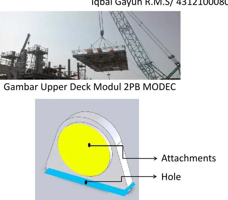
Iqbal Gayuh R.M.S/ 4312100080Gambar Upper Deck Modul 2PB MODEC
Attachments Hole
LATAR BELAKANG
Iqbal Gayuh R.M.S/ 4312100080PT. GPS Sekupang Logistic Blok D,
Batam
1. Berapa beban yang terjadi pada
point lifting
berdasarkan konfigurasi
rigging
dan beban tambah
yang dikenakan akibat perhitungan dinamik?
2. Bagaimana menentukan
unity check
pada member
deck
berdasarkan tiga konfigurasi
rigging
untuk
mengetahui apakah struktur gagal atau tidak pada
saat proses
lifting
?
3. Berapa
stress
yang terjadi pada
padeye
berdasarkan
konfigurasi
rigging
yang berbeda ditinjau dari
attachments
dan
hole padeye
?
4. Bagaimana perbedaan keandalan dari
padeye
berdasarkan konfigurasi
rigging
masing-masing?
RUMUSAN MASALAH
Iqbal Gayuh R.M.S/ 43121000801. Mengetahui beban yang terjadi pada
point
lifting
berdasarkan konfigurasi
rigging
dan
beban tambah yang dikenakan akibat
perhitungan dinamik.
2. Mengetahui gagal tidaknya struktur
deck
apabila
dikenakan tiga konfigurasi
rigging
yang berbeda.
3. Menghitung
stress
yang terjadi pada
padeye
berdasarkan konfigurasi
rigging
yang berbeda
ditinjau dari
attachments
dan
hole padeye.
4. Mengetahui perbedaan keandalan
padeye
berdasarkan konfigurasi
rigging
masing- masing
TUJUAN
Iqbal Gayuh R.M.S/ 43121000801. Beban yang dianalisis dalam penelitian ini sebatas beban struktur deck dan beban equipment di atas deck dan beban dinamik akibat angin.
2. Konfigurasi lifting yang digunakan meliputi satu spreader bar, dua spreader bar, dan tanpa spreader bar.
3. Material yang digunakan untuk spreader bar tidak dianalisis dan diasumsikan memenuhi kriteria yang diijinkan.
4. Pengelasan sambungan deck dan padeye diasumsikan normal dan tanpa cacat.
5. Analisis tegangan lokal dilakukan hanya pada struktur
padeye sedangkan analisis tegangan global dilakukan pada member struktur deck.
6. Software yang digunakan untuk membantu dalam penelitian ini adalah software SACS 5.6, dan Minitab.
BATASAN MASALAH
Iqbal Gayuh R.M.S/ 4312100080METODOLOGI PENELITIAN
Iqbal Gayuh R.M.S/ 4312100080 START Pengumpulan Data -Ukuran dek -Material dek -Pembebanan dek -Komponen lifting Perhitungan -Beban Struktur -COG struktur -Lifting pointPermodelan dengan SACS -Struktur deck - Rigging Configuration Analisis -Kekuatan member - Beban sling Perhitungan - Sling - Shackle -Dimensi Padeye A A BB
METODOLOGI PENELITIAN..2
Iqbal Gayuh R.M.S/ 4312100080A
A Analisis Dinamik Lifting Process
Analisis Kekuatan Padeye -Bearing Stress
-Shear Stress -Axial Stress -Tension Stress
Check Rules dengan AISC dan dokumen lifting
Analisis keandalan dengan Metode
MVFOSM FINISH
B B
Tidak
Layout Upper Deck
Iqbal Gayuh R.M.S/ 4312100080 W24x1Load Material dan Equipments
Iqbal Gayuh R.M.S/ 4312100080 Item No. Deskripsi unit (kg/m) Length (m) Weight (kg) Material Grade 1 UC 305x305x97 96.9 206.71 20030.199 S355JO 2 UB356x127x33 33.1 1.25 41.375 S355J2 3 W24x146 217.3 75.14 16327.922 S355JO Total Weight (kg) 37084.90 Item No. Deskripsi Weight (kg) 1 Cooler 1 3965 2 Cooler 2 5138 3 Cooler 3 9048 Total Weight (kg) 18151MTO & COG
Iqbal Gayuh R.M.S/ 4312100080 Ref 0,0,0 x 9908.015 mm y 4325.692 mm COG x 11285.467 mm y 4146.123 mm COG Total y xDistribusi Beban
Iqbal Gayuh R.M.S/ 4312100080 W1 W3 W4 W W2 W = 55235.9 kgW1.1 = 60759.49 kg (setelah dikalikan factor 1,1)
Lx = 14100 mm Ly = 8696 mm X1 = 8487.47 mm X2 = 5612.53 mm Y1 = 4146.12 mm Y2 = 4549.88 mm
Distribusi Beban..2
Iqbal Gayuh R.M.S/ 4312100080 W1 & W2 W3 & W4 X1 X2 W , = W , =Menghitung reaksi W1,2 dan W3,4
Beban Total (ton) Lx(mm) X1 X2 W1,2 W3,4
60,759.49 14100 8487.47 5612.53 24185.42 36574.07 Beban Total (ton) Ly(mm) Y1 Y2 W1 W2
24185.4 8696 4146.12 4549.88 11531.24 12654.18 W1 W2 Y2 = 4549.88 mm Y1 = 4146.12 mm W1 & W2
Beban Total (ton) Ly(mm) Y1 Y2 W3 W4
36574.1 8696 4146.12 4549.88 19136.11 17437.96 W3 W4 Y2 = 4549.88 mm Y1 = 4146.12 mm W3 & W4
Distribusi Beban..3
Iqbal Gayuh R.M.S/ 4312100080 Lifting Point Weight (kg) W1/P1 11531.24 W2/P2 12654.18 W3/P3 19136.11 W4/P4 17437.96 60759.4866Perhitungan Konfigurasi Rigging
Iqbal Gayuh R.M.S/ 4312100080
Perhitungan Konfigurasi Rigging
Iqbal Gayuh R.M.S/ 4312100080
Perhitungan Konfigurasi Rigging
Iqbal Gayuh R.M.S/ 4312100080
Sling Force
Iqbal Gayuh R.M.S/ 4312100080ℎ =
= × 3% - Berdasarkan DNV OS H205
PENDEKATAN RESPON DINAMIS
Perhitungan Beban Dinamis
Iqbal Gayuh R.M.S/ 4312100080 θ L W FW W FR FB FP A B = = (API 2A WSD (sect 2) FP = Gaya Pengembali = mg sinθ
W = m x g
FB = Gaya Sentrifugal = m x
Gaya Angin
Iqbal Gayuh R.M.S/ 4312100080= = (API 2A WSD (sect 2)
. Shape Coefficients (Cs). (API RP 2A, 2007)
Obyek Koefisien Bentuk
Beam Cylinders
Sides of Buiding
Projected Area of Platform
1,5 0,5 1,5 1,0
Gaya pada Sling
Iqbal Gayuh R.M.S/ 4312100080 θ L W FW W FR FB FP A B EKA+ EPA= EKB+ EPB EKA+ EPA = EKB+ EPB 0 + mg (1-cosθ) L = ½ m VB2+ 0 VB = 2 (1 − ) Kesetimbangan Energi... VB FP = W sin θ FW = FP Mencari θ FR – W = FB FR = FB + W FB = Gaya Sentrifugal = m x Mencari Gaya Sling FRPerhitungan Respon Dinamis
Iqbal Gayuh R.M.S/ 4312100080Apabila melihat hasil perhitungan respon struktur akibat gaya angin pada saat
pengangkatan dilakukan, apabila disesuaikan dengan ketentuan DNV pt2 Ch5-Lifting
(1996) dimana Dynamic Amplitude Factor untuk lifting di darat sebesar 1,10 , maka tepat pada kecepatan angin 18,7 km/jam dengan sudut kemiringan 12,8 derajat
Skala Kec. Angin (km/jam) FW (KN) W (KN) θ Vb (m/s) FR (KN) FR/W 0 1 0,34 541,31 0,04 0,00 541,31 1,0 1 2 1,37 541,31 0,15 0,00 541,31 1,0 3 3,09 541,31 0,33 0,00 541,31 1,0 4 5,49 541,31 0,58 0,01 541,31 1,0 5 8,58 541,31 0,91 0,02 541,31 1,0 2 6 12,36 541,31 1,31 0,04 541,32 1,0 7 16,82 541,31 1,78 0,08 541,33 1,0 8 21,97 541,31 2,33 0,13 541,37 1,0 9 27,80 541,31 2,94 0,22 541,47 1,0 10 34,33 541,31 3,64 0,33 541,67 1,0 11 41,54 541,31 4,40 0,48 542,08 1,0 3 12 49,43 541,31 5,24 0,68 542,86 1,0 13 58,01 541,31 6,15 0,94 544,25 1,0 14 67,28 541,31 7,14 1,27 546,64 1,0 15 77,24 541,31 8,20 1,67 550,59 1,0 16 87,88 541,31 9,34 2,17 556,90 1,0 17 99,21 541,31 10,56 2,77 566,73 1,0 18 111,22 541,31 11,86 3,49 581,64 1,1 19 123,92 541,31 13,23 4,35 603,79 1,1
Unity Check Member
Iqbal Gayuh R.M.S/ 4312100080 Member UC 0014-0018 0.280 0018-0047 0.280 0013-0014 0.273 0047-0048 0.270 0012-0013 0.252Penentuan Shackle
Iqbal Gayuh R.M.S/ 4312100080 Berdasarkan DNV OS-H205 Lifting, penentuan shackledidapatkan dari parameter SafeWorking Load (SWL). SWL pada umumnya digunakan sebagai referensi dari kekuaatan
shackle. SWL pada normalnya ditentukan oleh pihak Manufaktur atau Certifying Body.
Mengacu pada DNV, beban yang dikenakan pada shackle dianjurkan tidak lebih besar daripada nilai minimum dari:
1. Fsling < SWL x DAF = ( ) Fsling(kg) SWL (kg) Model A 22097,25 40176,82 Model B 21117,83 38396,05 Model C 20370,82 37037,85 SF = = 1 DAF = 1,1 (DNV)
Penentuan Shackle...2
Iqbal Gayuh R.M.S/ 4312100080Tipe Model Tipe SWL
(ton) (mm)A (mm)D1 (mm)C (mm)N Tanpa Spreader bar (model A) A085664 55 105 70 267 79,5
Satu Spreader bar (model B) A085556 42,5 95 65 222 57
Dua Spreader bar (model C) A085845 40 74 50 178 45
Penentuan Sling
Iqbal Gayuh R.M.S/ 4312100080 Berdasarkan DNV OS H205, penentuan design sling adalah...Dimana dari DNV OS H205 sebesar 3,0
<
=
MBL Model A Model B Model C Sling 1 (kg) 66291,75 63353,48 61112,45
Sling 2 (kg) n/a 100016,8 108661,3
Sling 1
Penentuan Sling...2
Iqbal Gayuh R.M.S/ 4312100080Sling 1
DESIGN PADEYE
DIMENSI | CHECK GEOMETRY |
STRESS
PADEYE...1
Iqbal Gayuh R.M.S/ 4312100080Dimensi
• Diameter Pinhole
• Radius Mainplate & Cheek • Padeye Thickness
• Panjang & Tinggi Padeye • Dimensi Stiffner
Code
Padeye...2
Iqbal Gayuh R.M.S/ 4312100080Diameter Pin Hole
Shackle Properties Dh Dpin DNV H-205 B.2.1 Dpin > 94% DhPadeye...3
Iqbal Gayuh R.M.S/ 4312100080Diameter Pin Hole cont..
• Dpin = 70 mmD
pinD
hPresentase
70
70
100.00%
70
71
98.59%
70
72
97.22%
70
73
95.89%
70
74
94.59%
70
75
93.33%
Dh = 74 mm
DpinPadeye...4
Iqbal Gayuh R.M.S/ 4312100080Padeye Thickness
> 75 % Inside Width
Shackle ( A )
tA
A = 105 mm
A t Presentase 105 105 100.00% 105 103 98.10% 105 100 95.24% 105 98 93.33% 105 96 91.43% 105 90 85.71% 105 79 75.24%T = 90 mm
Padeye Thickness cont..
= 90 mm = 50 mm = = 20 mm T Tpl TchRadius Main Plate dan Cheek
•
Radius Main Plate ( Rpl) >
1,25 Dh
•
Rpl < Length Inside Shackle (
C )- Dsling
C = 267 mm Dsling = 41,28 mm 92,5 mm< Rpl < 225,7 mm Rpl = 135 mmRadius Main Plate dan Cheek cont..
•
74 mm < Rch < 120 mm
Dh Rpl Weld Cheek Rch = 100 mmDimensi Padeye & Stiffner
Panjang, L : 410 mm L Ht Hh Lh Tinggi Padeye, Ht : 335 mm Tinggi Dasar – Hole, Hh : 200 mm Tepi – Hole, Lh : 205 mm Panjang, a : 139 mm Tebal, s : 20 mm Tinggi, Hs : 140 mm B Lebar, B : 328 mm a s HsCheck Padeye Stress
• Check Stress at Attachments of Padeye
+ +
Gaya- gaya pada Padeye
Fv
Fh
Fsl
Fv
Fh
Fx
• W tiap lifting = 19136,11 kg = 38272,22 lbs • Safety Factor = 2,00• Sudut lifting Ø = 60.32 deg
• Max. Vertical Force, Fv = 38272,22 kg = 76545,44 lbs
• Max. Lateral Force, Fl (3% x Fv) = 1148,17 kg = 2296,33 lbs • Max. Horizontal Force, Fh (Fv/tan Ø)= 15993,92 kg = 31987, 84 lbs
Check Stress Attachments of Padeye
• A = (H x B) – (h x
(B-Tpl))
= 31620 mm2= 49.01
in2
Section modulus of lugs
Zyy =(2sB3+h.tpl3) = 740727.6829 mm3 = 45.20 in3
Zxx=(BH3-h3(B-tpl)) = 3465265.854 mm3 = 211.46 in3
6B 6H
Section modulus of lugs
Zyy =(2sB3+h.tpl3) = 740727.6829 mm3 = 45.20 in3 Zxx=(BH3-h3(B-tpl)) = 3465265.854 mm3 = 211.46 in3 6B 6H MATERIAL Type Steel A36 σy= 36000 psi σu = 58000 psi
TENSILE STRESS
•
Allowable Stress, AISC 9
thEd. Sect D1.
•
St = 0.6 σy
= 21600 psi
•
Ft =
= 1561,78 psi
•
Check Ratio
= 7%
MATERIAL Type Steel A36 σy= 36000 psi σu = 58000 psi A = 49, 01 in2Fv
OK
SHEAR STRESS
•
Allowable Stress, AISC 9
thEd. Sect F4.
•
Ssy = 0.4 σy
= 14400 psi
•
Fsy =
= 900,6 psi
•
Check Ratio
= 6%
MATERIAL Type Steel A36 σy= 36000 psi σu = 58000 psi A = 49, 01 in2Fh
OK
SHEAR STRESS
•
Allowable Stress, AISC 9
thEd. Sect F4.
•
Ssy = 0.4 σy
= 14400 psi
•
Fsx =
= 46,85 psi
•
Check Ratio
= 0,3 %
MATERIAL Type Steel A36 σy= 36000 psi σu = 58000 psi A = 49, 01 in2Fl
OK
BENDING STRESS
•
Allowable Stress, AISC 9
thEd. Sect F1.1
•
Ssy = 0.66 σy
= 23760 psi
•
Fba = Hh x (
+
)= 16091,2 psi
•
Check Ratio
= 68 %
MATERIAL Type Steel A36 σy= 36000 psi σu = 58000 psi A = 49, 01 in2Fl
OK
Fh
HhTotal Stress & Unity Check Attachments
•
Total Stress
•
Fy =
( +
) +
+
= 17675,99 psi
•
Check Ratio,
= 49%
OK
•
Unity Check
•
(
)
= 0.52
OK
MATERIAL Type Steel A36 σy= 36000 psi σu = 58000 psi A = 49, 01 in2Check Stress Near Hole
• Stress Concentration
Factor
• buku Mechanics of Materials 2nd Ed. oleh
Madhukar Vable
Dh
Rpl
Tension Stress
•
Allowable Stress, AISC 9
thEd. Sect. D3
•
St
= 0,45 σy
= 16200 psi
•
Luas Area Horizontal
• Atv = 2 − ℎ + 2 2 ℎ − ℎ ℎ = 23 in2
•
Ftv =
= 7033,76 psi
•
Check Ratio
= 47%
MATERIAL Type Steel A36 σy= 36000 psi σu = 58000 psi K = 2,3Fv
OK
Tension Stress
• Allowable Stress, AISC 9th Ed. Sect. D3
• St = 0,45 σy = 16200 psi • Luas Area Vertikal
• Ath = − ℎ + 2 2 ℎ − ℎ ℎ = 28,04 in2 • Fth = = 3738,69 psi • Check Ratio = 23% MATERIAL Type Steel A36 σy= 36000 psi σu = 58000 psi K = 2,3
Fh
OK
Shear Stress
•
Allowable Stress, AISC 9
thEd. Sect. F4
•
Ssh = 0,4 σy
= 14400 psi
•
Luas Area
•
As =
( 2 − ℎ) +2 (2 ℎ− ℎ) ℎ= 23 in
2•
Fsy =
= 4557,4 psi
•
Check Ratio
= 32%
•
Fsx =
= 237,1 psi
•
Check Ratio
= 2%
MATERIAL Type Steel A36 σy= 36000 psi σu = 58000 psi K = 2,3Fh
Fl
Tear Out Stress
•
Allowable Stress, AISC 9
thEd. Sect. J4
•
Str = 0,3 σu
= 17400 psi
•
Luas Area
Atr =
2 − ℎ + 2 2 ℎ − ℎ ℎ= 23 in
2•
Ftr =
= 3842,65 psi
•
Check Ratio
= 22 %
MATERIAL Type Steel A36 σy= 36000 psi σu = 58000 psi K = 2,3Fsl
OK
Bearing Stress
• Allowable Stress, AISC 9th Ed. Sect. J8
• Sbr = 0,9 σy = 32400 psi • Luas Area Abr = Dpin (Tpl + 2 Tch) = 0,38 in2 • Fbr = = 9051,59 psi • Check Ratio = 28% MATERIAL Type Steel A36 σy= 36000 psi σu = 58000 psi K = 2,3
Fsl
OK
Total Stress & Unity Check
Attachments
•
Total Stress
•
Fy =
+
+
= 9126,31 psi
•
Check Ratio,
= 25%
OK
•
Unity Check
•
uc = (
)
= 0,35
OK
MATERIAL Type Steel A36 σy= 36000 psi σu = 58000 psiPerhitungan Tegangan Pada Attachments
Iqbal Gayuh R.M.S/ 4312100080
Nama
Model Shear Stress (psi)
Tensile Stress (psi) Bending Stress (psi) Total Stress (psi) Fsy Fsx Ft Fba Fy Uc Model A 900,6 46,9 1561,8 16091,2 17676,0 0,52 Model B 780,2 50,3 1675,1 10128,5 11829,5 0,35 Model C 341,3 71,1 2369,6 4146,5 6525,5 0,19
Perhitungan Tegangan Pada Hole
Iqbal Gayuh R.M.S/ 4312100080
Nama Model
Shear Stress
(psi) Tension Stress(psi) Tear out(psi) BearingStress (psi) Total Stress(psi)
Fsy Fsx Ftv Fth Ftr Fbr Fy Uc
Model A 4557,5 237,1 7903,3 3738,7 3842,7 9051,6 9126,3 0,35
Model B 4153,6 267,5 8917,7 3721,4 3956,3 9863,8 9841,2 0,37
Keandalan
Iqbal Gayuh R.M.S/ 4312100080Indeks Keandalan = = =
MVFOSM
Peluang Kegagalan = = 1 − ɸ
Dimana nilai, ɸ , didapatkan dari tabel distribus normal
Model
Hole Attachments
Stress (psi) Strength (psi) Stress (psi) Strength (psi)
S R S R
Tanpa Spreader bar 9126,3 36000,0 17676,0 36000,0
Satu Spreader bar 9841,2 36000,0 11829,5 36000,0
Keandalan
Iqbal Gayuh R.M.S/ 4312100080Dengan bantuan software minitab didapatkan distribusi normal dari variabel S dan R sebagai berikut,
Keandalan
Iqbal Gayuh R.M.S/ 4312100080Indeks Kehandalan Probality of failure S tress S trength μs μR σS σR β K = φβ Pf = 1 - φβ Tanpa S pread Bar 10421,64 ~ 37392,5241057 ~ 58914,6 24680,7 49200,0 6456,9 4900,0 3,02 0,99874 0,126% S atu S pread Bar 1663,9 ~ 31194,6 41057 ~ 58914,6 16167,0 49200,0 9000,0 4900,0 3,22 0,99936 0,064% Dua S pread Bar 438,45 ~ 25407,57 41057 ~ 58914,6 10968,0 49200,0 6051,0 4900,0 4,91 0,999999 0,0001% Tanpa S pread Bar 706 ~ 34478,66 41057 ~ 58914,6 16065,0 49200,0 8993,0 4900,0 3,24 0,99938 0,062% S atu S pread Bar 953,07 ~ 37431,47 41057 ~ 58914,6 16044,0 49200,0 9582,0 4900,0 3,08 0,99897 0,10% Dua S pread Bar 171,279 ~ 44561,7841057 ~ 58914,6 22087,0 49200,0 8225,0 4900,0 2,83 0,9977 0,23% Hole
Range (psi) Mean Deviasi S tandar
Attachments Padeye
Keandalan
Iqbal Gayuh R.M.S/ 4312100080SWL Dia. Hole
(ton) Padeye (in.) Hole Attach. Hole Attach.
PoF 0,126% 0,06% 0,0001% 0,062% 0,10% 0,23% Model B Model C Dia. Sling (in.) MBL (ton) ɸB 0,9938 0,99897 0,9977 A085845 40 2,25 61,1 2,05 0,99999 2,91 0,99874 A085556 42,5 2,25 63,3 2,56 0,99936
Tipe Model Tipe Shackle
A085664 55 2,25 66,3 Model A