MODEL EVALUATION OF PROTON EXCHANGE MEMBRANE FUEL CELL PERFORMANCE UTILIZING PLATINUM CATALYST
MUSTAPHA ISAH
A dissertation submitted in partial fulfilment of the requirements for the award of the degree of
Master of Science
Faculty of Science Universiti Teknologi Malaysia
JULY 2016
brought to you by CORE View metadata, citation and similar papers at core.ac.uk
DEDICATION
This dissertation is dedicated to my Parents, Siblings and all those that offered their prayers, supports and encouragements throughout my study period.
iv
ACKNOWLEDGEMENT
Let me start by thanking the almighty Allah (S.W.T) for his guidance throughout the period of my studies. My sincere appreciation also goes to my supervisor Assoc. Prof. Dr. Sib Krishna Ghoshal who happens to be a teacher and a mentor for his continuous support and encouragement to ensure that this work is a success. My earnest appreciation also goes to all the Staff of the Physics Department, my course mates and all well-wishers that contributed physically or in prayer to the success of this dissertation.
I would like to acknowledge the support of the Kaduna State Government and Kaduna Polytechnic, Nigeria for their financial support, which made this work successful.
"The financial support through vote 12H42, 13H50 (GUP/RU) and 4F424 (FRGS/MOHE) are also gratefully acknowledged".
ABSTRACT
Designing a more efficient and cost effective proton exchange membrane fuel cell (PEMFC) is highly required. This is due to its enormous potentials in portable and transportation applications. The main component that needs to be optimally design to achieve this purpose is the catalyst layer (CL) of the fuel cell. Recent studies have focused in effective utilization of the precious metal, usually platinum (Pt) which is used as the most effective catalyst so far. Two ways are employed to achieve this. Firstly, is by reducing the Pt mass loading and secondly is reducing the Pt to smaller nanoparticles to get more access surface area for the reacting fuel while at the same time reducing the overall cost of the system. Despite several experimental, complex model and simulation studies, simple ways of studying more effective utilization of the Pt catalyst are still inadquate. As a result, a simple model is developed by combining the effects of Pt catalyst particle size, Pt mass loading and Pt/C ratio in order to determine their influence on PEMFC performance. This was done by modeling the CL in the low current density of the fuel cell polarization curve only using the well known Butler-Volmer kinetics. The influence of nanoparticles of diameters between 1.5 nm to 6.5 nm, Pt mass loadings (0.4 mgPt/cm2, 0.35 mgPt/cm2, 0.05 mgPt/cm2 and 0.03 mgPt/cm2) and Pt/C ratio are examined. It is observed that the reduction in particle size increased the PEMFC performance. Furthermore, reduction of Pt mass loading increased the performance to certain limit of around 0.03 mgPt/cm2 loading. Supporting the Pt on carbon helped to reduce the amount of Pt used while improving fuel cell performance. The results are compared with other experiment and model findings. An important feature of this simple model suggests that it can be used to evaluate PEMFC performance without performing highly complex model calculations.
vi
ABSTRAK
Mereka bentuk sel bahan api membran pertukaran proton yang lebih cekap dan kos efektif (PEMFC) adalah amat diperlukan. Hal ini adalah kerana ia berpotensi besar dalam aplikasi mudah alih dan pengangkutan. Komponen utama yang perlu direka bentuk secara optimum untuk mencapai tujuan ini adalah lapisan pemangkin (CL) sel bahan api. Kajian kebelakangan ini telah memfokuskan penggunaan efektif logam berharga, kebiasaanya adalah platinum (Pt) yang digunakan sebagai pemangkin yang paling efektif setakat ini. Terdapat dua cara untuk menjayakan kajian ini. Pertama, adalah dengan mengurangkan jisim muatan Pt dan kedua adalah untuk mengecilkan Pt kepada nanopartikel yang lebih kecil bagi mendapatkan lebih banyak kawasan akses permukaan bahan api yang bertindak balas di samping mengurangkan kos keseluruhan sistem. Walaupun telah dijalankan beberapa kajian eksperimen, model kompleks serta simulasi, pembelajaran tentang penggunaan pemangkin efektif Pt, masih kurang mencukupi. Hasilnya, sebuah model ringkas telah dibina dengan menggabungkan kesan pemangkin Pt bersaiz zarah, jisim muatan Pt dan nisbah Pt/C untuk menentukan pengaruh mereka ke atas prestasi PEMFC. Ini dilakukan dengan pemodelan CL oleh sel bahan api polarisasi melengkung berketumpatan arus rendah sahaja. Pengaruh nanopartikel dengan diameter antara 1.5 nm kepada 6.5 nm, jisim muatan Pt (0.4 mgPt / cm2, 0.35 mgPt / cm2, 0.05 mgPt / cm2 dan 0.03 mgPt / cm2) dan nisbah Pt/C telah dikaji. Adalah diperhatikan bahawa pengurangan ke saiz zarah telah meningkatkan prestasi PEMFC tersebut. Tambahan pula, pengurangan jisim muatan Pt meningkatkan prestasi kepada had tertentu sekitar 0.03 mgPt / cm2 muatan. Penambahan Pt pada karbon membantu untuk mengurangkan jumlah penggunaan Pt disamping meningkatkan prestasi sel bahan api. Keputusan kajian dibandingkan dengan eksperimen dan model penemuan lain. Satu ciri penting dalam model ringkas ini menunjukkan bahawa ia boleh digunakan untuk menilai prestasi PEMFC tanpa melakukan pengiraan model yang sangat kompleks.
TABLE OF CONTENTS
CHAPTER TITLE PAGE
DECLARATION ii
DEDICATION iii
ACKNOWLEDGEMENT iv
ABSTRACT v
ABSTRAK vi
TABLE OF CONTENTS vii
LIST OF TABLES x
LIST OF FIGURES xi
LIST OF ABBREVIATIONS xiii
LIST OF SYMBOLS xiv
LIST OF APPENDICES xvi
1 INTRODUCTION 1
1.1 Introduction 1
1.2 Problem Background 3
1.3 Problem Statement 5
1.4 Research Objectives 6
1.5 Scope of the Study 7
1.6 Significance of the Study 8
1.7 Summary 8
2 LITERATURE REVIEW 10
2.1 Introduction 10
viii
2.2.1 PEMFC Working Principle 11
2.2.1.1 Anode Half Reaction 11
2.2.1.2 Cathode Half Reaction 12
2.3 Overview of PEMFC 14
2.3.1 PEMFC Discrete Components 15
2.3.1.1 Polymer Membrane 16
2.3.1.2 Catalyst Layer 18
2.3.1.3 Gas Diffusion Layer 19
2.3.1.4 Bipolar Plates 20
2.4 PEMFC Polarization Curve and Associated Voltage
Losses 21
2.4.1 Activation Losses 22
2.4.2 Ohmic Losses 24
2.4.3 Mass Transport Losses 24
2.4.4 Fuel Cell Voltage 25
2.5 PEMFC Modeling 26
2.5.1 Literatures On PEMFC Catalyst Layers 27
2.5.2 Microscale Models 28
2.5.3 Macroscale Models 30
2.6 Summary 36
3 METHODOLOGY 37
3.1 Introduction 37
3.2 Description of the Catalyst 38
3.3 The Proposed Model 39
3.4 Pt Surface Area per Unit Volume 42
3.5 Model Equation 43
3.6 Pseudo Code for the Polarization Curve in the Low
Current Density Region 44
3.7 Model Parameters 46
4 RESULTS AND DISCUSSION 48
4.1 Introduction 48
4.2 Model and Simulation Results 49
4.2.1 Size on Activation Region 49
4.2.2 Influence of Pt Mass Loading 51
4.2.3 Influence of Pt/C Loading 54
4.3 Model Validation 55
4.4 Summary 56
5 CONCLUSION AND FURTHER OUTLOOK 58
5.1 Conclusion 58
5.2 Further Outlook 59
REFERENCES 60
x
LIST OF TABLES
TABLE NO. TITLE PAGE
2-1 Variation of FC reversible voltage at different
temperatures and fuel states. 14
4-1 Parameters used in generating the model results. 47 4-2 Simulation values of current density for a range of
activation overpotential and different catalyst particle
LIST OF FIGURES
FIGURE NO. TITLE PAGE
1.1 A schematic diagram of a PEMFC (Harvey et al., 2008). 4 1.2 A typical catalyst agglomerate. (Harvey et al., 2008). 5 2.1 A 3-D Schematic of the working principle of a typical
PEMFC (direct hydrogen). (Yuan et al., 2012). The symbol in figure: (1) Bipolar plate; (2) backing layer; (3)
micro porous layer; (4) catalyst layer; (5) membrane. 12 2.2 Discrete components of a Single Cell PEMFC (Frano,
2005). 15
2.3 Schematic diagram of Nafion membrane (Frano, 2005)Error! Bookmark not defined. 2.4 Schematic Illustration of a CCL (Strahl et al., 2011). 19
2.5 PEMFC polarization curve showing its three main
voltage losses. 21
2.6 Activation losses as function of current density (Rao et
al., 2013). 22
3.1 Block diagram for modeling and simulation 38
3.2 Schematic diagram of the Catalyst Layer. 40
4.1 Variation of the overall cell voltage with current density
for the different catalyst particle sizes. 50 4.2 Variation of PEMFC current density with activation
overpotential for varying particle sizes. 51
4.3 Influence of 0.4 mgPt/cm2 loading on PEMFC
performance. 52
4.4 Influence of 0.35 mgPt/cm2 loading on PEMFC
xii
4.5 Influence of 0.05 mg/cm2 Pt loading on PEMFC
performance. 53
4.6 Influence of 0.03 mgPt/cm2 Pt loading on PEMFC
performance. 54
4.7 Influence of Pt/C ratio on the PEMFC performance. 55 4.8 Plotted experimental data, a model data and the current
LIST OF ABBREVIATIONS
FC - Fuel Cell
PEM - Proton Exchange Membrane
PEMFC - Proton Exchange Membrane Fuel Cell PEMCs - Proton Exchange Membrane Fuel Cells CL - Catalyst Layer
CCL - Cathode Catalyst Layer ACL - Anode Catalyst Layer Pt - Platinum
a.u. - Atomic Unit
ORR - Oxygen Reduction Reaction GDL - Gas Diffusion Layer
MPL - Micro Porous Layer
xiv
LIST OF SYMBOLS
i - Local current density (mA/cm2)
io iL ii - - -
Exchange current density (mA/cm2) Limiting current density (mA) Inonic current density (mA) apt, dPt mpt Pt/C LPt/C lc - - - - - -
Effective platinum catalyst reaction area per unit volume (m-1)
Pt particle diameter (nm) Pt mass loading (mg/cm2) Platinum-carbon ratio
Platinum-carbon loading (mg/cm2) Catalyst layer thickness (nm) - Oxygen concentration (molm-3)
n
- -
Reference oxygen concentration (molm-3) Number of electrons transfer
- Electron diffusion coefficient at the cathode (a.u) F - Faradays constant
R - Universal gas constant T - Operating temperature (K) Vact Vcell Erev Eirr Eo ROhm Rmt J - - - - - - - - Activation overpotential (mv) Cell voltage (V)
Reversible cell voltage (V) Irreversible cell voltage (V) Nernst’s voltage (V)
Ohmic resistance (Ω)
Mass transport resistance (Ω) Molar flux of reactants (
λ P+ - - - - Ionic conductivity Ionic potential (V)
water content or local ratio H2O/SO-3 in the membrane
Proton ions
xvi
LIST OF APPENDICES
APPENDIX TITLE PAGE
CHAPTER 1
1INTRODUCTION
1.1 Introduction
Recent high increase in energy demands and limited resources of energy has caused many concerns today. Despite that the usual conventional energy sources, such as fossil fuels, are still available in vast quantities, however they are not plenty and eventually will be exhausted. Moreover, environmental concerns, such as global warming, are rapidly becoming more alarming, and require serious attention and planning. Renewable energy sources are the solution to these pressing problems, since they are available so long as the sun is radiating its energy, and because they are sustainable as they have zero or negligible impact on the environment.
A promising technology which is based upon sustainable sources of energy such as hydrogen is the proton exchange membrane fuel cells (PEMFCs), which are also known as polymer electrolyte membrane fuel cells, are electrochemical devices that convert the chemical energy of hydrogen and oxygen into electricity with heat and water as by-products. PEMFCs operate at low temperature, high current density and high efficiency (Wang et al., 2011). As a result, PEMFCs are applied mainly in the automotive industry such as in fuel cell vehicles and occasionally in stationary power applications as well as in portable power applications such as laptops and mobile phones (Lemeš et al., 2006). PEMFCs are unique compared with other fuel cells in that they operate at low temperature which makes them quick to start up and easy to handle. Therefore, they have become research hotspots in various fields of science and technology, this is necessary in order to fully commercialized fuel cell
2
vehicles which will go a long way in reducing fossil fuels usage, which are currently the major sources of environmental pollutions and global warming. The preferred fuel for PEMFCs is hydrogen, which is generated by renewable power sources, such as solar or wind, will produce no greenhouse pollutants. Therefore, fuel cell technology has received a lots of attention in recent years.
Mathematical models and simulation are required as tools for design optimization of fuel cell systems. In order to understand and improve the performance of PEMFC systems, different mathematical models have been proposed (Al-Baghdadi, 2005; Ali & Aklil-D'Halluin, 2011; Cha & Lee, 1999; Wilson & Gottesfeld, 1992; Zhang, et al. 2013) to estimate the behaviour of voltage variation with output current density of a PEM fuel cell. Recently, numerical modelling and computer simulation have been performed to have a better understanding of the fuel cell itself (Al-Baghdadi, 2005; Famouri & Gemmen, 2003; Khan & Iqbal, 2005; Larminie & Dicks, 2003; Tanrioven & Alam, 2006). Numerical models are useful to simulate the inner details of PEMFC, but the calculation required for these models is too tedious to be used for system models. In system studies, it is important to have a simple model to estimate the performance of a PEMFC in terms of operating conditions without complex theoretical formulations, but only few studies have used simple models for this purpose (Al-Baghdadi, 2005).
In this study, the Cathode catalyst layer of a PEMFC system is modeled as a function of catalyst particle size and mass loadings. A Matlab (version 2014) is used in this modeling and simulation. The model consists of the simulation of current density dependence on catalyst particle size and mass loadings. Analysis of the resulting model will be used to explain how different catalyst particle sizes and mass loadings affect the low current density region also known as the activation region of a PEM fuel cell.
1.2 Problem Background
Proton exchange membrane fuel cells (PEMFCs), being clean and high density energy sources, will go a long way in reducing global energy demands by providing other alternative sources of clean energy such as in portable devices, stationary power and transportations applications. Unfortunately, their commercialization is limited due to their high cost and scarce reliability (Carrera-Cerritos et al., 2014). Currently, the fuel economy of the hydrogen fuel cell automotive systems can be 2-3 times the fuel economy of the conventional internal combustion engines. The current status of the transportation cost of the PEMFC is $61/kW (2009), which is almost double the price of $30/kW that the USA Department of Energy (DOE) targeted by 2015 (Brunner, Marcks, Bajpai, Prasad, & Advani, 2012). One of the major cause of PEMFC high cost is the Platinum catalyst used for both hydrogen oxidation reaction (HOR) at the anode and oxygen reduction reaction at the cathode (ORR), which is a precious metal and highly expensive but is considered as the most efficient catalyst so far for both anode and cathode electrodes (Bond, 1975). Due to this limitation, extensive studies on how to produce optimum performance electrodes with reduced Platinum catalyst loadings has been carried out (Cha & Lee, 1999; Gasteiger et al., 2004; Ralph et al., 1997; Wilson & Gottesfeld, 1992; Wilson, Valerio, & Gottesfeld, 1995). Two methods are usually employed to achieve low platinum loading in PEM fuel cells: Either to develop a platinum based alloyed catalyst or to search for a non-precious material catalyst with better performance (Zhong et al., 2006). Another possible way to attain higher performance with less platinum loading is to reduce platinum particle size to nanoscale, this is based on the fact that the catalyst performance depend on the active or effective surface area of the fuel cell catalysts (Gasteiger et al., 2004).
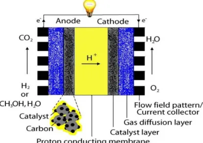
This research work seeks to use simple mathematical model to study the performance of PEMFC base on varying catalyst particles sizes and mass loadings. This will be used to explore more on how the nanoparticles based electro-catalyst can improve fuel cell performance while reducing the overall cost of the system. Figure 1.1. shows a schematic diagram of the PEMFC which comprises of the gas diffusion layer, anode catalyst layer, proton exchange (conducting) membrane and
4
the cathode catalyst layer. In the diagram, an enlarged picture of the catalyst layer is shown with the platinum particles supported on a carbon particles of wider surface area. The PEMFC performance will be studied by employing these varying nanoparticles of diameters (1.5 nm, 2.5 nm, 3.5 nm and 6.5 nm in diameters) with different Pt and Pt/C loadings.
In this study, a Butler-Volmer type kinetics of the catalyst layer that originally relates the output current density and the geometric surface area of the catalyst will be modified to describe the catalyst at nanoparticles level, this will be combined with the effects of mass loadings and Pt/C ratio. After combining these models, the resulting hybrid model will be used for the study.
Figure 1.1 A schematic diagram of a PEMFC (Harvey et al., 2008).
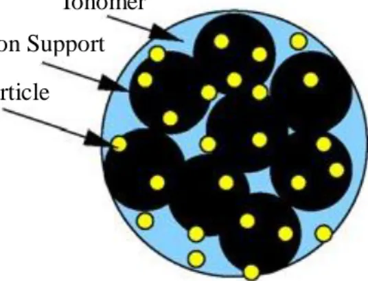
A schematic of catalyst layer is shown in Figure 1.2. This shows how platinum nanoparticles are supported or dispersed on the surface of carbon material (usually Vulcan XC72). The platinum particles are loaded on carbon black material which has porosity fabrication technology to extend the reactive area from plane (two dimension) to interspace (three dimension), this will enable more availability of reaction sites, thereby, also increasing reaction rate in PEMFC (Zhang, Lu, & Wen, 2013). The Pt/C catalyst particles are held together by a polymeric electrolyte
material, such as Nafion, which also double as a path (ionomer) for electron conduction in the catalyst layer. The Platinum supported on carbon will be assumed to form an agglomerate. The catalyst agglomerates shapes are considered to be of one of the following forms; spherical, cylindrical or slab; with the pore space of the catalyst which are assumed to be among the percolating network of agglomerates, thereby, allowing for fluid/fuel transport. In this model, a spherical shape agglomerate and spherical platinum particles will be considered. The agglomerate model will be extended to the discrete particles level and the catalyst layer will be model as function of the discrete particle’s effective area, which is also a function of particle size. The relations of mass loading and the Pt/C ratio will also be incorporated in the model to describe their various effects on the fuel cell performance.
Figure 1.2 A typical catalyst agglomerate. (Harvey et al., 2008).
1.3 Problem Statement
Reducing noble metals usage in a given fuel cell by reducing the bulk catalyst used to nanoparticles sizes has been experimentally used as one of the key method in reducing fuel cell cost as well as also improving it performance (Bond, 1975). In addition, it increases the surface area to volume ratio of the catalyst used, thereby increasing available reaction sites for the fuel catalysis. Many experimental works
Ionomer Carbon Support Pt particle
6
have been done on this aspect but very limited mathematical models are developed to study these effects. Activation overpotential, due to the reaction kinetics at the surface of the electrodes is the dominant losses in low current density region of proton exchange membrane (PEM) fuel cells (Niya & Hoorfar, 2014) and thereby, limiting its performance that need to be carefully investigated. Therefore, the study intends to focus on the low current density region by evaluating how different catalyst particle sizes and mass loadings influence PEMFC in the activation region. A simple model is still lacking to determine the mechanism of improved performance and the effects of all the studied parameters.
The study will be carried out through matlab simulations of the resulting developed equations. The overall performance of the PEM fuel cell will then be evaluated based on the outcome of the simulation result.
1.4 Research Objectives
i. To combine Butler-Volmer kinetics equation by incorporating the influence of catalyst particle size and mass loadings at Pt catalyst particles level for obtaining an effective expression related to fuel cell performance.
ii. To evaluate the influence of different Pt nanoparticle sizes in the low current density region of PEMFC.
iii. To determine the effects of mass loadings (platinum and Pt/C loadings) in the activation region of the cathode catalyst layer of PEMFC.
iv. To validate the model results by comparing with other findings. v. To determine the relationship between varying parameters with
1.5 Scope of the Study
Many models have been developed for PEMFCs, but most of the models did not clearly explained the effects of particle size on the output current and voltage of the fuel cell. But a good number of models have explained very well the effects of Pt mass loadings and platinum-carbon (Pt/C) ratio (Gasteiger et al., 2004; Ralph et al., 1997; Wilson & Gottesfeld, 1992; Wilson et al., 1995) . This current density dependence of particle size can be explored to study and understand more on the major fuel cell losses which includes: activation losses, ohmic losses and concentration losses of the fuel cells. Therefore, the scope of this work includes:
i. Incorporate the well-established Butler-Volmer kinetics with the effect of catalyst particle size, Pt mass loading and Pt/C loading to produce a modified model that will directly accounts for the influence of particle size, Pt mass loading and Pt/C loading on the output current density and voltage of the fuel cells in the activation region.
ii. Simulate the resulting expressions using Matlab program to get different Platinum catalyst size, mass loading and catalyst dependence-current density, which will particularly be used to explain the fuel cell polarization curve in the activation region.
iii. Analyse the data obtained to understand how the catalyst particle size, mass loading and Pt/C ratio influence the activation region of the PEMFC.
iv. Compare the results of the new model with existing experimental and other simulation data to check its validity.
8
1.6 Significance of the Study
The quest for more commercially viable proton exchange membrane fuel cell is an important field of study in renewable energy. Since it was discovered that PEMFC, Unlike heat engine, has higher theoretical efficiency of about 83% (Barbir, 2005; Frano, 2005; Larminie & Dicks, 2003), coupled with its low emission has attracted a lots of interest in automobile and other energy applications. But the fuel cell maximum theoretical efficiency is far from being achieved due to many losses associated with the system. Hence, its commercialization is still not fully attained. One way toward attaining this efficiency is the use of a noble catalyst to speed up of the rate of fuel conversion (Gasteiger et al., 2004). The most efficient and stable catalyst for PEMFCs so far is platinum or platinum-based alloyed supported on carbon (Bond, 1975). Platinum being a precious metal which is usually very expensive and limited, it tremendously contributed to the high cost of the fuel cell system. Many experimental studies have been geared toward optimizing the amount of platinum used for an optimum performance of the fuel cells, but theoretical work on that aspect is limited. Hence this work will provide a theoretical model that can be used to study the optimum loading of the precious metal catalyst for different catalyst particle sizes. This will give more insights on how to enhanced the overall performance of the PEMFC system. It will also help to highlights more on how to reduce cost associated with the trial and errors associated with experimental work.
1.7 Summary
In summary, it has been long observed that reduction in dimensionality of the catalyst material from bulk to the nanometer scale changes virtually all of its most basic properties in a fundamental way. Its surface area to volume ratio increases with particle size reduction and also its shape and crystalline structure
changes with varying particle sizes. The main change of concern here is that of the surface area to volume ratio. It is highly desirable to employ them in a form such that the largest possible fraction of the atoms is at the surface and hence available to the reactants. This can only be achieved by reducing them into small nanoparticles having a higher surface to volume ratio. This unique properties of materials attracted the interests of researchers to use and explore possibilities of reducing the loadings of this noble catalyst while improving its performance to an amount that will be viable for the commercialization of the fuel cells. It’s expected that when this is achieved, the full potential of PEM fuel cell technology will be the feature in energy consumption in the area of transportation and also in portable and stationary power sources. This work will make use of these properties to study the effects of catalyst particle size, Pt Loading and Pt/C loading in the activation region of the PEMFC polarization curve.
60
REFERENCES
Ali, D., & Aklil-D'Halluin, D. D. (2011). Modeling a proton exchange membrane (PEM) fuel cell system as a hybrid power supply for standalone applications. Paper presented at the Power and Energy Engineering Conference (APPEEC), 2011 Asia-Pacific.
Amphlett, J. C., Baumert, R., Mann, R. F., Peppley, B. A., Roberge, P. R., & Harris, T. J. (1995). Performance modeling of the Ballard Mark IV solid polymer electrolyte fuel cell I. Mechanistic model development. Journal of the
Electrochemical Society, 142(1), 1-8.
Antoine, O., Bultel, Y., Durand, R., & Ozil, P. (1998). Electrocatalysis, diffusion and ohmic drop in PEMFC: Particle size and spatial discrete distribution effects.
Electrochimica Acta, 43(24), 3681-3691.
Barbir, F. (2005). PEM Fuel Cells: Theory and Practice (Sustainable World Series). Bernardi, D. M., & Verbrugge, M. W. (1992). A mathematical model of the solid‐
polymer‐electrolyte fuel cell. Journal of the Electrochemical Society, 139(9), 2477-2491.
Berning, T., Lu, D. M., & Djilali, N. (2002). Three-dimensional computational analysis of transport phenomena in a PEM fuel cell. Journal of Power
Sources, 106(1), 284-294.
Bond, G. C. (1975). Small particles of the platinum metals. Platinum Metals Review,
19(4), 126-134.
Bultel, Y., Ozil, P., & Durand, R. (1999). Modelling of mass transfer within the PEM fuel cell active layer: limitations at the particle level. Journal of applied
electrochemistry, 29(9), 1025-1033.
Butel, Y., Ozil, P., Durand, R., & Simonsson, D. (1995). Study of Mass Transfer within the Active Layer of PEMFC Electrodes at the Particle Level. Paper presented at the Electrochemical Society Proceedings.
Carrette, L., Friedrich, K., & Stimming, U. (2001). Fuel cells–fundamentals and applications. Fuel Cells, 1(1), 5-39.
Cetinbas, F. C., Advani, S. G., & Prasad, A. K. (2014). Three dimensional proton exchange membrane fuel cell cathode model using a modified agglomerate approach based on discrete catalyst particles. Journal of Power Sources, 250, 110-119.
Cha, S., & Lee, W. (1999). Performance of proton exchange membrane fuel cell electrodes prepared by direct deposition of ultrathin platinum on the membrane surface. Journal of the Electrochemical Society, 146(11), 4055-4060.
Dutta, S., Shimpalee, S., & Van Zee, J. (2001). Numerical prediction of mass-exchange between cathode and anode channels in a PEM fuel cell.
International Journal of Heat and Mass Transfer, 44(11), 2029-2042.
Fuller, T. F., & Newman, J. (1993). Water and thermal management in solid‐ polymer‐electrolyte fuel cells. Journal of the Electrochemical Society, 140(5), 1218-1225.
Gasteiger, H., Panels, J., & Yan, S. (2004). Dependence of PEM fuel cell performance on catalyst loading. Journal of Power Sources, 127(1), 162-171. Gurau, V., Liu, H., & Kakac, S. (1998). Two‐dimensional model for proton exchange
membrane fuel cells. AIChE Journal, 44(11), 2410-2422.
Herrera, O., Wilkinson, D., & Mérida, W. (2012). Anode and cathode overpotentials and temperature profiles in a PEMFC. Journal of Power Sources, 198, 132-142.
Khalatur, P. G., Talitskikh, S. K., & Khokhlov, A. R. (2002). Structural Organization of Water‐Containing Nafion: The Integral Equation Theory. Macromolecular
theory and simulations, 11(5), 566-586.
Kim, S. H., & Pitsch, H. (2009). Reconstruction and effective transport properties of the catalyst layer in PEM fuel cells. Journal of the Electrochemical Society,
156(6), B673-B681.
Koyama, M., Kim, D., Kim, B., Hattori, T., Suzuki, A., Sahnoun, R., . . . Takaba, H. (2008). Multi-scale simulation approach for polymer electrolyte fuel cell cathode design. ECS Transactions, 16(2), 57-66.
Lange, K. J., Sui, P.-C., & Djilali, N. (2010). Pore scale simulation of transport and electrochemical reactions in reconstructed PEMFC catalyst layers. Journal of
62
Lange, K. J., Sui, P.-C., & Djilali, N. (2012). Determination of effective transport properties in a PEMFC catalyst layer using different reconstruction algorithms. Journal of Power Sources, 208, 354-365.
Larminie, J., & Dicks, A. (2003). Fuel cell systems explained (Vol. 2).
Lin, G., He, W., & Van Nguyen, T. (2004). Modeling liquid water effects in the gas diffusion and catalyst layers of the cathode of a PEM fuel cell. Journal of the
Electrochemical Society, 151(12), A1999-A2006.
Lipnizki, F., Hausmanns, S., Ten, P.-K., Field, R. W., & Laufenberg, G. (1999). Organophilic pervaporation: prospects and performance. Chemical Engineering Journal, 73(2), 113-129.
Mann, R. F., Amphlett, J. C., Hooper, M. A., Jensen, H. M., Peppley, B. A., & Roberge, P. R. (2000). Development and application of a generalised steady-state electrochemical model for a PEM fuel cell. Journal of Power Sources,
86(1), 173-180.
Marr, C., & Li, X. (1999). Composition and performance modelling of catalyst layer in a proton exchange membrane fuel cell. Journal of Power Sources, 77(1), 17-27.
Natarajan, D., & Van Nguyen, T. (2001). A two-dimensional, two-phase, multicomponent, transient model for the cathode of a proton exchange membrane fuel cell using conventional gas distributors. Journal of the
Electrochemical Society, 148(12), A1324-A1335.
Niya, S. M. R., & Hoorfar, M. (2014). Determination of Activation Losses in Proton
Exchange Membrane Fuel Cells. Paper presented at the ASME 2014 12th
International Conference on Fuel Cell Science, Engineering and Technology collocated with the ASME 2014 8th International Conference on Energy Sustainability.
O’Hayre, R., Cha, S.-W., Colella, W., & Prinz, F. B. Fuel cell fundamentals. 2006 John Wiley & Sons. New York.
Paddison, S. J., Paul, R., & Zawodzinski, T. A. (2000). A statistical mechanical model of proton and water transport in a proton exchange membrane. Journal
of the Electrochemical Society, 147(2), 617-626.
Pasaogullari, U., & Wang, C.-Y. (2005). Two-phase modeling and flooding prediction of polymer electrolyte fuel cells. Journal of the Electrochemical
Ralph, T., Hards, G., Keating, J., Campbell, S., Wilkinson, D., Davis, M., . . . Johnson, M. (1997). Low cost electrodes for proton exchange membrane fuel cells performance in single cells and Ballard stacks. Journal of the
Electrochemical Society, 144(11), 3845-3857.
Rao, S. S. L., & Shaija, A. (2013). Mathematical modeling and performance analysis
of proton exchange membrane fuel cell. Paper presented at the Power, Energy
and Control (ICPEC), 2013 International Conference on.
Santarelli, M., Torchio, M. F., & Cochis, P. (2006). Parameters estimation of a PEM fuel cell polarization curve and analysis of their behavior with temperature.
Journal of Power Sources, 159(2), 824-835.
Shi, Z., Wang, X., & Zhang, Z. (2006). Comparison of two-dimensional PEM fuel
cell modeling using COMSOL multiphysics. Paper presented at the
Proceedings of the COMSOL users conference.
Siddique, N., & Liu, F. (2010). Process based reconstruction and simulation of a three-dimensional fuel cell catalyst layer. Electrochimica Acta, 55(19), 5357-5366.
Sierra, J. M., Pathiyamattom, S. J., & Gamboa, S. (2009). Study of activation losses and ohmic resistance in a PEM fuel cell using computational fluid dynamics.
ECS Transactions, 20(1), 395-405.
Singh, D., Lu, D., & Djilali, N. (1999). A two-dimensional analysis of mass transport in proton exchange membrane fuel cells. International Journal of
Engineering Science, 37(4), 431-452.
Smitha, B., Sridhar, S., & Khan, A. (2005). Solid polymer electrolyte membranes for fuel cell applications—a review. Journal of membrane science, 259(1), 10-26.
Springer, T. E., Zawodzinski, T., & Gottesfeld, S. (1991). Polymer electrolyte fuel cell model. Journal of the Electrochemical Society, 138(8), 2334-2342. Strahl, S., Husar, A., & Serra, M. (2011). Development and experimental validation
of a dynamic thermal and water distribution model of an open cathode proton exchange membrane fuel cell. Journal of Power Sources, 196(9), 4251-4263. Tsuchiya, H., & Kobayashi, O. (2004). Mass production cost of PEM fuel cell by learning curve. International Journal of Hydrogen Energy, 29(10), 985-990.
64
Wang, G., Mukherjee, P. P., & Wang, C.-Y. (2006). Direct numerical simulation (DNS) modeling of PEFC electrodes: Part I. Regular microstructure.
Electrochimica Acta, 51(15), 3139-3150.
Wang, G., Mukherjee, P. P., & Wang, C.-Y. (2007). Optimization of polymer electrolyte fuel cell cathode catalyst layers via direct numerical simulation modeling. Electrochimica Acta, 52(22), 6367-6377.
Wang, L., Husar, A., Zhou, T., & Liu, H. (2003). A parametric study of PEM fuel cell performances. International Journal of Hydrogen Energy, 28(11), 1263-1272.
Wilson, M. S., Valerio, J. A., & Gottesfeld, S. (1995). Low platinum loading electrodes for polymer electrolyte fuel cells fabricated using thermoplastic ionomers. Electrochimica Acta, 40(3), 355-363.
Xing, L., Mamlouk, M., & Scott, K. (2013). A two dimensional agglomerate model for a proton exchange membrane fuel cell. Energy, 61, 196-210.
Yan, Q., & Wu, J. (2008). Modeling of single catalyst particle in cathode of PEM fuel cells. Energy Conversion and Management, 49(8), 2425-2433.
Zhang, J., Yang, W., Xu, L., & Wang, Y. (2011). Simulation of the catalyst layer in PEMFC based on a novel two-phase lattice model. Electrochimica Acta,
56(20), 6912-6918.
Zhang, J. R., Lu, C. D., & Wen, D. H. (2013). Study on Performance of PEMFC