DIFFERENTIAL EVOLUTION FOR OPTIMIZATION OF PID GAIN IN ELECTRICAL DISCHARGE MACHINING CONTROL SYSTEM
Trias Andromeda1,2, Azli Yahya1, Syahrullail Samion3, Ameruddin Baharom1and Nor Liyana Hashim4 1Faculty of Electrical Engineering, Universiti Teknologi Malaysia, Johor, Malaysia
2Department of Electrical Engineering, Diponegoro University, Semarang, Indonesia 3Faculty of Mechanical Engineering, Universiti Teknologi Malaysia, Johor, Malaysia
4Faculty of Health Science and Biomedical Engineering, Universiti Teknologi Malaysia, Johor, Malaysia
E-mail: [email protected]; [email protected]; [email protected]; [email protected]; [email protected]
ICETI 2012-B2008_SCI
No. 13-CSME-29, E.I.C. Accession 3487
ABSTRACT
PID controller of servo control system maintains the gap between Electrode and workpiece in Electrical Dis-charge Machining (EDM). Capability of the controller is significant since machining process is a stochastic phenomenon and physical behaviour of the discharge is unpredictable. Therefore, a Proportional Integral Derivative (PID) controller using Differential Evolution (DE) algorithm is designed and applied to an EDM servo actuator system in order to find suitable gain parameters. Simulation results verify the capabilities and effectiveness of the DE algorithm to search the best configuration of PID gain to maintain the electrode position.
Keywords: servo control system; electrical discharge machining; proportional integral derivative; con-troller tuning; differential evolution.
ÉVOLUTION DIFFÉRENTIELLE POUR L’OPTIMISATION DE GAIN D’UN DÉRIVÉ PROPORTIONNEL INTÉGRAL (PID) DANS UN SYSTÈME DE COMMANDE
D’ÉLECTRO-ÉROSION PAR DÉCHARGE ÉLECTRIQUE RÉSUMÉ
Le dispositif de commande dérivée proportionnelle intégrale (PID) d’un système servomoteur maintient l’es-pace entre l’électrode et la pièce à usiner par électroérosion (EDM). La capacité du dispositif de commande est importante car ce procédé d’usinage est un phénomène stochastique, et le comportement physique de la décharge est imprévisible. Par conséquent, un dispositif de commande dérivée proportionnelle intégrale (PID), utilisant un algorithme à évolution différentielle (ED) est conçu et appliqué au système d’électroé-rosion par décharge électrique (EDM) afin de trouver les paramètres de gain appropriés. Les résultats de simulation ont permis de vérifier les capacités de l’algorithme à évolution différentielle pour trouver la meilleure configuration du dispositif de commande dérivée proportionnelle (PID) pour maintenir la position de l’électrode.
1. INTRODUCTION
PID controller is the most popular ones on dealing with industrial control processes. It is reliable in op-eration, robust in performances and up to 90% of all control strategies are PID. Various applications have implemented using this PID controller, such as process control, motor drives, automotive, flight control [1]. On the contrary, determination of optimal configuration parameters for PID constants is very challenging. It has been experimentally checked that more than 30% of the installed controllers are operating in manual mode and 65% of the automatic close loops are operated in poorly tuned condition [2], so new approaches algorithm to adjust PID gain controller are very important.
Tuning methods of PID parameters are classified into traditional and intelligent methods. Conventional methods such as Zigler–Nichols [3] and simplex methods are not simple and difficult to be implemented in digital system. Using these conventional methods, system response produces surge and big overshoot. Recently, intelligent approaches such as genetic algorithm, particle swarm optimization have been proposed for PID optimization. Among them, genetic algorithm (GA) has a significant contribution and has been applied successfully to solve many problems of optimal PID controller parameters. In the past decades, different tuning methodologies of PI and PID controllers have been proposed in literatures such as auto tuning, self-tuning and computational intelligence [1, 4, 5].
Many researchers have tried to propose a new algorithm or strategy in order to obtain a good technique to determine gain parameters in PID controller. Conventional or traditional methods called Zigler–Nichols try to find a suitable PID constants configuration based on step response analysis [6], so the accuracy of capturing the step response graph is significantly contributed to the determination of PID parameters. Ar-tificial Intelligence algorithm tries to find optimum parameter in PID controller based on fitness function. During the training step, the parameters will be updated until the system response has fulfilled the objective function requirement.
Unfortunately, it is not easy to find a proper configuration gains of PID controllers because many industrial plants are often burdened with problems such as high order, time delays, poorly damped, nonlinearities and time-varying dynamics. Over the years, several authors have proposed the tuning of PID to control variable processes by optimization methods, such as genetic algorithms [7–13], particle swarm optimization [14, 15], tribes algorithm [16], harmony search [17, 18], evolution strategy [19], ant colony [20]. Moreover in [21] other artificial intelligence technique called fuzzy is used as an active suspension system controller using fuzzy-skyhook control theory, which offers new opportunities for the improvement of vehicle ride perfor-mance. Meanwhile, sliding mode control as an alternative way to design an optimal control is applied to spherical robot [22]. In this paper, Differential Evolution as a new Evolutionary Algorithm is used as a tool for solving the class of multi objective optimization problems that results from a PID design problem for maintaining the gap between electrode and workpiece in EDM system process. The fitness function which is called Integral Absolute Error (IAE) is chosen to obtain an automatic method for designing single-loop PID controllers.
2. SYSTEM DESCRIPTION
Fig. 1. Basic elements of an EDM system [23].
Fig. 2. Block diagram of an existing EDM servo control system.
the workpiece through an insulated dielectric fluid. This removes tiny particles of metal, called debris, from the workpiece.
Figure 1 shows basic elements of the EDM system. When the gap between the electrode and workpiece is sufficiently small (10–50µm), said gap being controlled by the position control servo system, an electrical spark occurs in the gap. In this process, which is also known as a discharge, current is converted into heat [25, 26]. The surface of the material is very strongly heated in the area of the discharge channel. If the flow of current is interrupted, the discharge channel collapses very quickly. Consequently the molten metal on the surface of the material evaporates explosively and takes liquid material with it down to a certain depth. Then a small crater is formed. If the process which is started from movement of electrode downward to workpiece until a small crater is formed is followed by another, new craters are formed next to the previous ones and the workpiece surface is constantly eroded.
3. GAP CONTROL IN EDM SYSTEM
Machining gap is adjusted using ram servo control system at a critical distance for the continuous occurrence of electric discharge. In the same EDM power generator settings, the machining stability and productivity depend on the performance of this servo control mechanism. Figure 2 shows the block diagram of a EDM servo control unit.
In general, there are three components which construct the EDM servo control system. Kc is applied at
Fig. 3. Practical gap control system of an EDM [27].
Fig. 4. Block diagram of the EDM gap control system [27].
it with a servo reference voltage (Vs). The differences betweenVgandVs, known as error, is fed to amplifier
Kc, denoted byVsd, drives the servo ram to adjust the gap distance so as to keepVg at a level determined
byVs. The feedback signal contains the information relating to gap impedance but does not include details
about gap state parameters such as normal sparking, harmful arcing, etc. The control gainKcand the level
ofVsare manually preset according to the operator’s experiences. It has been noted that the conventional
servo system does not effectively respond to either gap state parameters or process dynamic and stochastic features [27]. With this type of control system, therefore, the machining process is not optimal.
Figure 3 shows a practical gap control system of EDM process. The dynamic relationship between the feed rate fr(s)and the speedV(s)can be expressed as
V(s) = −ks
s2+2ξ ωns+ωn2
, (1)
whereks is a magnification constant. The termsξ andωn is damping ratio and natural frequency of the
servo system.
According to the foregoing analysis, the system is a type 1 system when the gap controllery(s)is a pure
proportional controller. A Proportional Derivative (PD) controller is applied to the system to improve the transient responses. Accordingly, fr(s)can be expressed as
Fr(s) =Kpe(s) +Kdse(s). (2)
Figure 4 shows the complete block diagram.
4. DIFFERENTIAL EVOLUTION (DE)
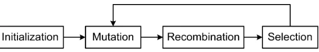
Fig. 5. Flow graph of differential evolution algorithm.
(PSO) but DE has some advantages. In general, DE has three main advantages (1) able to locate the accurate global optimum irrespective of the initial parameter values (2) has rapid convergence (3) utilizes few control parameters, thus easy and simple to use. During optimization step, crossover/recombination, mutation and selection operators are involve in this computation. Initially, population is given randomly. DE utilize mutation operator as a search mechanism and selection operation to search directly based on prospective regions on search space. DE algorithm is applied based on several steps. Figure 5 shows the flow graph of DE algorithm.
4.1. Initialization
Suppose a function withDreal parameters will be optimized. The size of population,N, must be determined to be at leastN=4. Parameter vectors as a candidate solution to multidimensional optimization problems have the form Xi,G= [X1,i,G,[X2,i,G, . . . ,[Xj,i,G, . . . ,[XD,i,G], where I =1,2, . . . ,N andG is the generation
number. The initial value for each candidate is uniform randomly selected in the interval[XL,XH], where
X L= [X1,L,X2,L, . . . ,XD,L]andXH= [X1,H,X2,H, . . . ,XD,H]are the lower and upper bound of search space,
respectively:
Xj,i,0=XL+ rand[0,1](XH−XL). (3)
4.2. Mutation
When a given parameter vector Xi,G, three vectors (Xr1,G,Xr2,G,Xr3,G) are randomly chosen in the range [1,NP], such that indicesi,r1,r2 andr3 are different. A donor vectorVi,Gis proposed by adding weighted
difference between two vectors to the third (called base) vector as
Vi,G=Xr1,G+F(Xr2,G−Xr3,G), (4)
whereF is a mutation scaling factor, which is typically chosen from the range[0,1].
4.3. Recombination
Donor vectorVi,G+1and target vectorXi,Gare mixed to get a trial vector
Ui,G= [U1i,G,U2i,G, . . . ,Uji,G, . . . ,UDi,G]. (5)
In this paper, a binomial recombination is applied. The recombination is defined as
Uji,G=
(
Vj,i,G, if rand≤CRor j= jrand
Xj,i,G, otherwise
(6)
where J=1,2, . . . ,Dand I=1,2, . . . ,N. CR is known as a crossover rate and has a function to control parameter alternative of DE similar toF. jrand∈[1,2, . . . ,D]is randomly selected index to ensure thatUi,G
Fig. 6. DE-PID controller block diagram.
4.4. Selection
In order to realize the selection operators, Eq. (7) is defined as
Xi,G+1=
(
Ui,G, ifJ(Ui,G)<(Xi,G)
Xi,G, otherwise
(7)
J(X)is the fitness function which will be optimized. In this work, the fitness function is Integral absolute
error soJ(X)must be minimized. Thus, if a new trial vector select a lower value of the fitness function, it swaps the corresponding target vector in the next generation; otherwise the vector target is still at the same value. Hence, population will get better performance or still remains as a previous fitness value.
5. IMPLEMENTATION OF DE-PID CONTROLLER
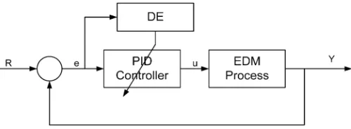
Contribution of this paper is to apply the DE method in order to search an optimize configuration of PID gains controller of EDM Die-Sinking. A new control system optimization called DE-PID control system is proposed. Figure 6 shows the proposed controller block diagram.
The Differential Evolution (DE) algorithm is a promising new optimization technique which will be used to search an optimize parameters value in PID controller. At the first process, EDM model is controlled by initial PID parameter value. As stated before, Integral Absolute Error (IAE) will be used as a fitness function. Once the IAE is computed by Simulink software, it can be used as an Objective target value in the Differential Evolution (DE) algorithm. The DE will compute a new population based on this IAE value. In this work, DE is applied using matlab m.files coding. DE will propose a new population and then will be use as a new PID parameters value for the next generation.
The PID control algorithm involves three separate parameters, they are proportional gainKp, integral gain
Kiand derivative gainKd. The mathematical description of the PID controller is shown as
u(ti) =Kp.e(ti) +Ki.
The objective function which is used to optimize the PID parameter is
J= 1
r(i) andx(i) present the reference input and observed output responses. A DE algorithm is proposed to
adjust three parameters, Kp, Ki andKd, iteratively and repeatedly until they reach optimal values and the
Table 1. Experimental results for P, PI, PID and PD controller.
No Kp Ki Kd IAE
PSO DE PSO DE PSO DE PSO DE
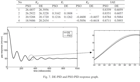
1 26.4857 26.3956 – – – – 0.8359 0.6059 2 26.2922 26.3228 0.3162 0.1808 – – 0.8351 0.6057 3 20.5288 20.1720 0.1216 0.1262 –0.4600 –0.4657 0.8784 0.5884 4 18.9486 20.2434 – – –0.5056 –0.4618 0.8711 0.5893
Fig. 7. DE-PID and PSO-PID response graph.
Fig. 8. Learning convergence of fitness value.
6. SIMULATION RESULTS
Simulation is conducted for several combinations. PID is configured to construct four types of controller, i.e., P, PI, PID and PD controller. Each controller is tuned by Differential Evolution (DE) and Particle Swarm Optimization (PSO). The results can be seen in Table 1.
Figure 7 shows a gap response graph for the PID controller which is tuned by DE and PSO. The initial position for the electrode is 225 micron and the target is 50 micron. It can be seen that DE and PSO give a similar response graph. There are small differences between the two response graphs, as shown in the enlarged graph in Fig. 7. Both optimization methods successfully find optimum gain parameters for the PID controller.
Figure 8 shows learning convergence of fitness value for DE and PSO optimization. The figure depicts 25 iterations. At first iteration, both algorithm compute fitness function using initial value for each PID gain parameter. DE and PSO try to find an optimum value forKp,KiandKd during its searching process. PSO
gives more fluctuates fitness value comparing to DE. The figure also shows that fitness objective function output from DE optimization which uses IAE is smaller. The figure also shows that DE gives better result in term of fast convergence. Therefore, less time is required when DE is applied to tune the PID gain.
7. CONCLUSION
In this paper, the PID controller parameters have been tuned by two artificial intelligence methods. This paper compares DE as an alternative algorithm to particle swarm optimization to show the advantages of DE. The simulation results reveal that determination of each parameter (Kp,Ki andKd) is achieved
auto-matically. Gap between electrode and workpiece can be maintained satisfactory. Differential Evolution and Particle Swarm Optimization successfully tune all combination of P, I and D parameters. The response of all combination of PID shows that the optimum gap can be achieved. However every combination has different response to reach the setting value. PID controller tuned by DE shows the best performance to reach the setting parameter with minimum fitness function value. In addition, the tuned PID controller using DE has resulted less processing time.
ACKNOWLEDGEMENT
The authors are grateful for the financial support from the Research Management Centre (RMC) of Univer-siti Teknologi Malaysia.
REFERENCES
1. Åström, K.J. and Hägglund, T. “The future of PID control”, Control Engineering Practice, Vol. 9, pp. 1163–
1175, 2001.
2. Ender, D.B., “Process control performance: Not as good as you think”,Control Engineering, Vol. 40(10), pp.
180–190, 1993.
3. Wenge, Lv., Deyuan, Li., Cheng, Luo, S., Zhang, X. and Zhang, L., “Research on PID control parameters tun-ing based on election-survey optimization algorithm”, inProceedings International Conference on Computing, Control and Industrial Engineering (CCIE), pp. 323–326, 2010.
4. Åström, K.J. and Hägglund, T., PID Controllers: Theory, Design and Tuning, 2nd edn. Research Instrument
Society of America, Triangle Park, North Carolina, USA, 1995.
5. Cominos, P. and Munro, N., “PID controllers: recent tuning methods and design to specification”,IEE Proceed-ings – Control Theory and Applications, Vol. 149, pp. 46–53, 2002.
6. Saranya, M. and Pamela, D., “A real time IMC tuned PID controller for DC motor”, International Journal of Recent Technology and Engineering, Vol. 1, pp. 65–70, April 2012.
7. Altinten, A., Ketevan lioglu, F., Erdogan, S., Hapoglu, H. and Alpbaz, M., “Self-tuning PID control of jacketed batch polystyrene reactor using genetic algorithm”,Chemical Engineering Journal, Vol. 138, pp. 490–497, 2008.
8. Pai-Yi, H. and Yung-Yaw, C., “Design of PID controller for precision positioning table using genetic algorithms”, inProceedings of the 36th IEEE Conference on Decision and Control, Vol. 3, pp. 2513–2514, 1997.
10. Jan, R.-M., Tseng, C.-S. and Liu, R.-J., “Robust PID control design for permanent magnet synchronous motor: A genetic approach”,Electric Power Systems Research, Vol. 78, pp. 1161–1168, 2008.
11. Krohling, R.A. and Rey, J.P., “Design of optimal disturbance rejection PID controllers using genetic algorithms”,
IEEE Transactions on Evolutionary Computation, Vol. 5, pp. 78–82, 2001.
12. Chun-Liang, L., Horn-Yong, J. and Niahn-Chung, S., “GA-based multiobjective PID control for a linear brush-less DC motor”,IEEE/ASME Transactions on Mechatronics, Vol. 8, pp. 56–65, 2003.
13. Takahashi, R.H.C., Peres, P.L.D. and Ferreira, P.A.V., “Multiobjective H2/H8 guaranteed cost PID design”,IEEE Control Systems, Vol. 17, pp. 37–47, 1997.
14. Kim, T.H., Maruta, I., and Sugie, T., “Robust PID controller tuning based on the constrained particle swarm optimization”,Automatica, Vol. 44, pp. 1104–1110, 2008.
15. Hashim, N.L.S., Yahya, A., Andromeda, T., Kadir, M.R.A., Mahmud, N. and Samion, S., “Simulation of PSO-PI controller for micro-EDM system in biomedical application”,Procedia Engineering – Elsevier, Vol. 41, pp.
805–811, 2012.
16. Coelho, L.d.S. and Bernert, D.L.d.A., “PID control design for chaotic synchronization using a tribes optimization approach”,Chaos, Solitons & Fractals, Vol. 42, pp. 634–640, 2009.
17. Coelho, L.d.S. and Andrade Bernert, D.L., “An improved harmony search algorithm for synchronization of discrete-time chaotic systems”,Chaos, Solitons & Fractals, Vol. 41, pp. 2526–2532, 2009.
18. Coelho, L.d.S. and Mariani, V.C., “An improved harmony search algorithm for power economic load dispatch”,
Energy Conversion and Management, Vol. 50, pp. 2522–2526, 2009.
19. Coelho, L.d.S. and Coelho, A.A.R., “Automatic tuning of PID and gain scheduling PID controllers by a de-randomized evolution strategy”,Artificial Intelligence for Engineering Design and Manufacturing, Vol. 13, pp.
365–373, 1999.
20. Duan, H.b., Wang, D.b. and Yu, X.f., “Novel approach to nonlinear PID parameter optimization using ant colony optimization algorithm”,Journal of Bionic Engineering, Vol. 3, pp. 73–78, 2006.
21. Soliman, A.M.A., Kaldas, M.M.S., Barton, D.C. and Brooks, P.C., “Fuzzy-skyhook control for active suspension systems applied to a full vehicle model”,International Journal of Engineering and Technology Innovation, Vol.
2, pp. 85–96, 2012.
22. Yue, M. and Liu, B.Y., “Design of adaptive sliding mode control for spherical robot based on MR fluid actuator”,
Vibroengineering Journal of Vibroengineering, Vol. 14, 2012.
23. Yahya, A. and Manning, C.D., “Determination of material removal rate of an electro-discharge machine using dimensional analysis”,Journal Physics D: Applied Physics, Vol. 37, pp. 1467–1471, 2004.
24. Yahya, A., Minhat, A.E., Andromeda, T., Khamis, N.H.H., Khalil, K., and Rahim, M.A.A., “Communication within hardware of electrical discharge machining (EDM) system”,Jurnal Teknologi Special Edition, pp. 201–
211, May 2011.
25. Yahya, A., Andromeda, T., Baharom, A., Rahim, M.A.A., and Mahmud, N., “Material removal rate prediction of electrical discharge machining process using artificial neural network”,Journal of Mechanics Engineering and Automation, Vol. 1(A204), pp. 298–302, September 2011.
26. Yahya, A., Andromeda, T., Minhat, A.E., Khamis, N.H., Khalil, K., and Rahim, M.A.A., “Comparison studies of Electrical Discharge Machining (EDM) process model for low gap current”,Advanced Materials Research,
Vol. 433–440, pp. 650–654, 2012.
27. Chang, Y., “VSS controller design for gap control of EDM”, International Journal of the Japan Society of Mechanical Engineering (JSME), Vol. 45(3), pp. 712–721, 2002.
![Fig. 1. Basic elements of an EDM system [23].](https://thumb-ap.123doks.com/thumbv2/123dok/2205437.1224962/3.612.207.401.64.252/fig-basic-elements-edm.webp)
![Fig. 3. Practical gap control system of an EDM [27].](https://thumb-ap.123doks.com/thumbv2/123dok/2205437.1224962/4.612.148.466.67.195/fig-practical-gap-control-edm.webp)