ASSEMBLY PROJECT
Test Project Document
LKS_2017_TP16_ASM_EN
Submitted by:
Name : Electronics Indonesia Member : ASC WSC
Contents
This Test Project proposal consists of the following documentation/files:
1.
LKS_2017_TP16_ASM_EN.doc2.
LKS_2017_ TP16_ASM _01_EN.pdf3.
LKS_2017_ TP16_ASM _02_EN.pdf4.
LKS_2017_ TP16_ASM _03_EN.pdf5.
LKS_2017_ TP16_ASM _04_EN.pdf6.
LKS_2017_ TP16_ASM _05_EN.pdf1. INSTRUCTIONS
Competitors are given 4 hours to complete an electronics assembly project. This test project shall access competitors in the following areas:
a. Ability to assemble an electronic project based on given drawings, specifications and instructions like :
Schematic Diagrams
PCB Layout Diagrams
Assembly Photographs
Component Part Lists
Component Data Sheets
b. Ability to verify proper operation of an electronic project after assembly like :
Interpret test specifications
Demonstrate proper operation of complete project2. DESCRIPTION PROJECT AND TASKS
3. Product Testing:
Pre-Testing:
Adjust variable resistor VR2 & VR1 to obtain correct 5V supply on both board.
Upon power on:
LED D1 (Green): On (Indicating of 5VDC incoming is available)
LED D65 (purple): On
LED D1 – D64 (Green): Off
Triggering Start Button (Selector ‘0’): Mode Hard Boiled Egg LED Running Down and Music is on.
Buzzer will beep thrice upon finish counting.
Triggering Start Button (Selector ‘1’): Mode Half Boiled Egg LED Running Down and Music is on.
4. INSTRUCTION TO THE COMPETITORS
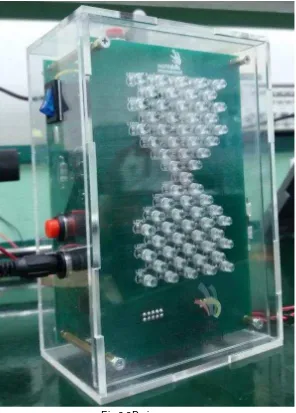
a. Assemble components for Control board and Display board according to given component in part list. The height of LED in Display board is shown in figure below:
5.
Equipment, machinery, installations and materials required.Proposal committee prepares the following equipment, machinery, installations and materials.
Item Qty Material Description Notes
1 1 set All parts 2 1 Safety glass 3 1 Cotton Glove 4
Competitor prepares the following equipments, machinery, installations and materials.
Item Qty Material Description Notes
2 1 Universal Digital or
Multi-meter V, Ω, A, etc
10 1 Precise screwdriver For trimmer resistor
11 1 Screw driver + type
12 1 Screw driver - type
13 1 Brush
No. No. Part Value Qty. Note
Part List PCB Panel Assembly Project
No. No. Part Value Qty. Note
No. No. Part Value Qty. Note
4. PCB Panel 16 x 20 CM 1 PCB Panel Double Layer
Part list Assembly Project
No. Name Part Value Qty. Note
1. Swith SPDT 3 PIN 1
2. Swith SPST 2 PIN 1
3. Push Buttom 2 PIN 1
4. Speaker 8Ω 0,1W 2 PIN 1
5. Spicer Hexagonal Female-Female
0,8 CM 4
6. Spicer Hexagonal Female-Male 4 Cm 4
7. Spicer Hexagonal Female-Male 0.5 Cm 4
8 Acrylic 116x170x76
MARKING SCHEME
MAX MARK ASPECT OF CRITERION - DESCRIPTION
5 D1. Operating Condition
OTHERS
i.
Wiring Specificationa)
Wire Speaker (Both Yellow)b)
Start Buttonc)
Power Switchd)
DC Jack Connectore)
Selector Switch (Time 1 = O, Time 2 = I)g)
Wire LengthWIRE LABEL COLOUR LENGTH (mm) DESCRIPTION
L1 - 1.3 +/- 0.2 Stripped wire to solder joint
60 +/- 2.0 Multicore, 0.6mm Diameter