MODULASI
AM(DSB-SC,SSB dan VSB)
Apa itu Modulasi ?
Modulasi adalah pengaturan
parameter dari sinyal pembawa
(carrier) yang berfrequency
tinggi sesuai sinyal informasi
(pemodulasi) yang frequencynya
lebih
rendah,
sehingga
informasi
tadi
dapat
disampaikan.
Mengapa Perlu Modulasi ?
Meminimalisasi interferensi sinyal
pada pengiriman informasi yang
menggunakan frequency sama atau
berdekatan
Dimensi antenna menjadi lebih
mudah diwujudkan
Sinyal
termodulasi
dapat
dimultiplexing dan ditransmisikan via
sebuah saluran transmisi
MODULASI ANALOG
Modulasi Sinyal Continue (continues wave) :
Amplitude Modulation (AM)
Modulasi Sudut (Angle Modulation) :
Phase Modulation (PM)
Frequency Modulation (FM)
Modulsi Pulsa
Pulse Amplitude Modulation (PAM)
Pulse Wide Modulation (PWM)
Jenis Modulasi (2)
Pulse Code Modulation (PCM)
Delta Modulation (DM)
Amplitude Shift Keying (ASK)
Frequency Shift Keying (FSK)
Phase Shift Keying (PSK)
Quadrature Amplitude Modulation (QAM)
Quaternary PSK (QPSK)
Continous Phase FSK (CPFSK)
5
SINYAL PEMBAWA
6
Persamaan sinyal pembawa /carrier :
Vc(t) = Vc sin (
ct +
)
Modulasi amplitude
(amplitude modulation,
AM)
Modulasi sudut
(angle modulation)
Modulasi frekuensi
(frequency modulation, FM)
Modulasi fase
(phase modulation, PhM)
Analisa pada bab ini :
menggambarkan sinyal termodulasi kawasan waktu dan spektrumnya dengan pemodulasi/informasi m(t):
m(t) sinusoidal
m(t) sembarang pada selang [fa fb] menghitung bandwith
menghitung distribusi dari daya sinyal
menerangkan deteksi sinyal
Gambar spektrum sinyal diturunkan dari persamaan Sinyal kawasan frekuensi → spektrum amplitudo PADA FREKUENSI POSITIF / PITA SATU SISI
x(t) = A1 cos(2 f1t) + A2 cos(2 f2t)
X(f) =A1 (f-f1)+A2 (f-f2)
f
1f2
A
1A
2X(f)
f
Review kawasan waktu
frekuensi
s(t) = A Cos 2
f
c
t
fc
0 f
S(f)
A/2
- fc
Amplitudo sinyal carrier dibuat berubah-ubah secara proporsional sesuai perubahan yang terjadi pada sinyal pemodulasi (sinyal informasi)
Persamaan Sinyal Carrier :
Secara umum, persamaan sinyal carrier termodulasi adalah :
dimana :
carrier
sesaat
Phasa
)
(
carrier
sesaat
Amplitudo
)
(
Carrier
frequency
2
t
t
V
f
C C
V
t
t
V
c(
)
ccos
c
(
)
cos
)
(
)
(
mod
t
V
t
t
t
S
c
10
Pada AM, amplitudo dibuat berubah sesuai sinyal informasi, sedang phasanya dibuat nol, sehingga persamaan sinyal termodulasi secara umum adalah :
m(t) = sinyal informasi / pemodulasi
t
t
m
t
Varian dari Modulasi
Amplitudo
Double Side Band
Suppressed
Carrier
(DSB-SC)
Double Side Band
Full
Carrier (DSB-FC)
Single Side Band (SSB)
Vestigial Side Band (VSB)
Double Side Band Suppressed
Carrier (DSB-SC)
Dibuat dengan mengatur agar amplitudo sinyal
carrier berubah secara proporsional sesuai
perubahan amplitudo pada sinyal pemodulasi (sinyal
informasi)
Persamaan Matematis DSB-SC
Dibangkitkan dengan mengalikan sinyal informasi
m(t)
dengan sinyal carrier yang dihasilkan
oscillator
t
t
m
t
S
DSB
SC
(
)
(
)
cos
c
m(t)
t
c
cos
t t
m t
SDSBSC( ) ( )cosc
AM DSB SC
kawasan waktu, informasi sinusoidal tunggal
m(t)
Vc(t)
SDSB SC(t)
m(t) = sinyal pemodulasi (modulating signal) Vc(t) = sinyal pembawa = Vc cos(2π fc t)
SDSB SC(t) = sinyal hasil modulasi atau sinyal termodulasi DSB-SC
t
frek=fp
phase shift
t
Vc
t m(t) = Vm cos 2fmt
Pemodulasi m(t) sinusoidal / cosinus
m(t) = Vm cos(2fmt)
SDSB-SC(t) = Vc Vm cos(2fct) cos(2fmt)
= {cos 2[fc+fm]t+cos 2[fc-fm]t}
fc-fm fc+fm Spektrum LSB USB fc VcVm 2 f Supressed carrier
Distribusi daya sinyal :
Ptotal DSB SC =
2 2 m .V c V 2 2 m .V c V 2 VcVm
2 2
Daya rata-rata (pada beban 1Ω)
AM DSB SC kawasan frekuensi
(Spektrum AM DSB SC), dengan informasi sinusoidal tunggal
PITA SATU SISI
Spektrum
m(t)
M(f)
Persamaan Matematis
Gambar Spektrum Sinyal DSB-SC
Spektrum AM DSB SC dengan informasi
sinyal sembarang
m(t)
M(f)
USB LSB LSB USB ) (f SDSBSC
0 fc
c
f
(fcfm) fcfm fcfm
) (fcfm
15
)
(
2
1
)
(
2
1
)
(
c cSC
DSB
f
M
f
f
M
f
f
S
PITA DUA SISI
suppressed carrier / menghilangkan komponen pemmbawa v
c(t)
fm
fc
fc - fm
fc
fc + fm
0
0
0
Contoh lain penggambaran spektrum AM DSB
SC dengan informasi sinyal sembarang,
m(t)
M(f)
SDSB SC(t) = m(t).Vc(t)
PITA SATU SISI
16
Modulasi dgn m(t) sembarang → hanya diwakili oleh spektrum amplitudo
fa fb
0
M(f)
M
f
Hasil modulasi : S DSB SC (t) akan memiliki spektrum amplitudo
fc - fb fc + fb
0
SAM-DSB-SC(f)
f
BW
fc
2 M
Contoh lain modulasi AM-DSB-SC
(informasi/pemodulasi sembarang m(t)
17
Proses demodulasi dilakukan dengan mengalikan sinyal carrier termodulasi dengan sinyal local oscillator (pada penerima) yang sama persis dengan sinyal oscillator pada pemancar, kemudian memasukan hasilnya ke sebuah low pass filter (LPF)
Syarat penting :Local Oscillator harus menghasilkan sinyal cos ωct yang frequency dan phasa nya sama dengan yang dihasilkan oleh oscillator pada pemancar
(Synchronous Demodulation/Detection) ( atau Coherent detection)
Demodulasi/Deteksi Sinyal
DSB-SC
d(t)
t
c
cos
) (t SDSBSC
LPF
) (
Deteksi Sinyal DSB-SC (kondisi ideal)
S DSB SC (t) = Vc Vm cos(2fct) cos(2fmt)
VLOcos( 2fct)
m(t) ^ fm< fco << fc
Asumsi :
Gain filter lowpass = 0 dB (1 kali)
SDSB SC(t) = 2m V c V
Cos 2(fc+fm)t +
2m V c V
Cos 2(fc-fm)t
Dari hasil perkalian : d(t) = SDSB-SC (t) x VLO cos (2fct)
Hanya ada dua komponen frekuensi yang lolos keluar dari filter lowpass, yaitu :
4 V
VcVm LO Cos {2(fmt)} +
4 V
VcVm LO Cos {2(fmt)}
= VcVm2 VLO Cos {2fmt} =
m(t) ^
Gambarkan proses deteksi sinyal AM-DSB-SC
pada kawasan frekuensi (titik A, B, C, D):
a. Untuk informasi sinusoidal tunggal
b. Untuk informasi sembarang m(t)
Gambarkan dalam pita 2 sisi dan pita 1 sisi
Latihan
Deteksi Sinyal DSB-SC
(ada perbedaan fasa antara lokal osilator pengirim & penerima)
S DSB SC (t) = Vc Vm cos(2fct) cos(2fmt)
VLOcos( 2fct+)
m(t) ^ fm< fco << fc
Asumsi :
Gain filter lowpass = 0 dB (1 kali)
Dari hasil perkalian : SDSB-SC (t) x VLO cos (2fct + ) 2m V c V
Cos 2(fc+fm)t +
2 m V p V
Cos 2(fc-fm)t SDSB SC(t) =
A
B C
Hanya ada dua komponen frekuensi yang lolos keluar dari filter lowpass, yaitu :
akan menentukan amplitudo dari hasil deteksi → maks. = 0º
→ nol = 90º
4 V
VcVm LO Cos {2(fmt) - } +
4 V
VcVm LO Cos {2(fmt) + }
= VcVm2 VLO Cos {2fmt} X cos
= m(t) ^
Deteksi Sinyal DSB-SC
(ada perbedaan fasa antara lokal osilator pengirim & penerima)
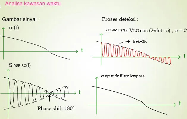
Gambar sinyal :
t
S DSB-SC(t)
Phase shift 180º
Proses deteksi :
x VLO cos (2fct+) , = 0º
S DSB-SC(t)
t
frek=2fc
t
output dr filter lowpasst
m(t)
Modulasi AM-DSB-SC
(informasi/pemodulasi sembarang m(t) Analisa kawasan waktuSingle Side Band (SSB)
Dikembangkan karena DSB-SC membutuhkan
Bandwith yang besar (2 kali bandwith sinyal
informasi)
Ternyata USB atau LSB mengandung informasi
yang
lengkap,
sehingga
dirasa
cukup
mentransmisikan salah satu side band saja
Spektrum AM-SSB
24
USB USB
) ( f SSSBUSB
0 fc
c
f
LSB LSB
) ( f SSSBLSB
0 fc
c
f
Frequency Discrimination Method
Pembangkitan Sinyal SSB
t
c
cos )
(t m
BPF
) (t SSSB
) (t SDSB
25
f spektrum m(t)
fb
fa
f
fc
Spektrum SSSB USB
fc+fb
f spektrum SDSB SC
fc
fc-fb fc+fb
Persamaan sinyal SSB
Misal : m(t) = Vm cos (2fmt)
Carrier : Vc(t) = Vc cos 2fct
SDSB-SC (t) = Vm Vc/2 cos 2(fc + fm)t + Vm Vc/2 cos 2(fc – fm)t
USB LSB
Kasus USB :
SSSB-USB(t) = Vm Vc/2 cos[2 (fc +fm)t]
m(t) = Vm cos 2fmt
AM SSB
kawasan waktu, informasi sinusoidal tunggal
t
fc+fm
VcVm
2
fc
f
“( spektrum sinyal SSB-USB dengan Carrier = fc)”
t
27
Phase Shift MethodPembangkitan Sinyal SSB lainnya
2 2 t c cos t c sin ) ( ˆ t m + -) (t m t t
m( )cosc
Demodulasi Sinyal SSB
d(t)
t
c
cos
)
(
t
S
SSBLPF
)
(
t
y
Sinyal SSB di-demodulasi dengan cara yang sama dengan demodulasi sinyal DSB-SC (Synchronous Detection)
Deteksi Sinyal SSB-LSB (kondisi ideal)
Vc Vm cos 2(fc+fm)t 2
Filter Base Band
^ m(t)
VLO cos (2fct)
Keluaran filter hanya ada 1 komponen frekuensi : Vc Vm VLO cos (2fmt) =
4
^ m(t)
f
spektrum SSB-LSB
fc
fc-fb
spektrum (SSBxLO)
fb
2fc ffa
fb
fa
Filter Base Band
Keluaran filter hanya ada 1 komponen frekuensi :
Vc Vm VLO cos (2fmt-) , tidak mempengaruhi amplitudo hasil
4 deteksinya. Dengan kata lain ada offset frek. di LO
Vc Vm cos 2(fc+fm)t 2
^ m(t)
VLO cos (2fct+)
Deteksi Sinyal SSB-SC
(ada perbedaan fasa antara lokal osilator pengirim & penerima)
Deteksi Sinyal SSB-SC
(ada perbedaan frekuensi dan fasa antara lokal osilator pengirim & penerima)
Vc Vm cos 2(fc+fm)t 2
Filter Base Band
^ m(t)
VLO cos {2(fc+f)t+}
Vc Vm VLO cos (2fm+f)t-), f = ada pergeseran spektrum hasil deteksi
4
Vestigial Side Band (VSB)
Merupakan kompromi (jalan tengah) antara SSB dan DSB
Biasanya digunakan dalam transmisi sinyal video pada televisi
32
Spektrum VSB
c
f
c
f
Sinyal VSB dapat dibangkitkan dengan proses seperti terlihat pada diagram blok berikut
Pembangkitan Sinyal VSB
t
c
cos
2
)
(
t
m
VSB FILTER
)
(
t
S
VSBVestigial sideband modulation (VSB-AM)
di B
f
fc
fc-fb fc+-fb
H(f) Sideband Shaping
fc fc+fb f
2fv
0 f
Spektrum m(t)
fb
t
c
cos
2
)
(
t
m
VSB FILTER
)
(
t
S
VSBB
fc f
Detektor Envelope / selubung
detektor sinkron
Demodulator VSB:
R
LC
S
VSB(t)
Vo
35
S
VSB(t)
V(t)
Vo(t)
Latihan soal:
Di bawah ini adalah diagram blok suatu proses translasi spektrum frekuensi
Spesifikasi :
Frekuensi cut off LPF = 5 kHz
Frekuensi lokal oscilator_1 ( fOL-1 ) = 50 kHz ; Pass band BPF-1 = [50 – 55] kHz
Sinyal di titik A = sinyal analog dengan spektrum = [300 -- 4000] Hz
a). Gambarkan spektrum frekuensi di titik B , C dan D !
b). Tentukan harga frekuensi oscilator_2 dan pass-band BPF-2 agar di titik F diperoleh sinyal SSB-USB dengan frekuensi pembawa 1400 kHz.
Perhitungan harus dilengkapi gambar spektrum di titik E dan F !
c). Ulangi point b) agar di F diperoleh sinyal SSB-LSB dengan frekuensi pembawa 1400 kHz !
LPF BPF-1 BPF-2
f
OL-1f
OL-2
A B C D E F