This article outlines the development of pier protection against ship collision over the last 25 years. The calculation of impact forces is developed from general formulas for equivalent loads, based on collision tests, to numerical FEM simulations. Compari-sons between the results are given. Examples of the structural protection of 18 bridges are described.
1 Introduction
In 1980 the author had to design the protection against ship collision for the existing Zarate Brazo-Largo Bridges across the River Paranà in Argentina. An investigation into the state of the art at that time showed that little systematic re-search and virtually no code recommendations existed. The author therefore had to undertake his own investigations.
The most important characteristics of any investigation into ship collisions with bridges are the determination of the impact forces and the structural design of the protec-tion against those forces. In the following the author out-lines his personal experience gained from more than 25 years of dealing with the protection of bridges against ship collision. The examples of the structural design of the dif-ferent types of pier protection have mostly been designed or checked by the author’s firm Leonhardt, Andrä & Partner.
2 Collision forces
The only theoretical investigation available in 1980 was that by Minorsky[1], who had investigated the forces act-ing in head-on collisions between two ships. Fig. 1 shows the
linear relationship between the volume of the deformed steel in both ships and the absorbed energy. However, this determination of impact forces is only valid for a collision between two ships.
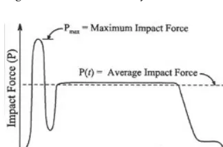
For the protection of bridge piers, the head-on collision of a ship against a rigid wall as shown in Figs. 2 and 3 is im-portant. For this purpose the results of collision tests carried out in Germany under the direction of Gerhard Woisinwere evaluated [2], Fig. 4. Woisin found a dynamic relationship between the impact forces over time as shown in Fig. 5, where the maximum force for about 0.1 to 0.2 seconds at the beginning of the collision increases up to double the value of the average collision force over several seconds.
From Woisin’s test results the author concluded that equivalent static impact forces from a direct collision of a large ship against a rigid wall are, in a first approximation, proportional to the square root of the dead weight tonnage (DWT) of the ship, see Fig. 6. However, within this rela-tionship a wide scatter of impact forces exists for ships with the same DWT due to their widely varying hull structures and collision speeds. The author thus proposed the for-mula for the impact forces with a scatter of ± 50 %.
(Svensson, 1981), where P is the equivalent average impact load in MN.
This formula was published by the author in Germany in 1981 [3], in the IABSE Periodica in 1982 [4], and in the Proceedings of the IABSE Colloquium on Ship Collision with Bridges held in Copenhagen in 1983 [5].
P = 0 88. DWT ◊ ±50%
Protection of bridge piers against ship collision
Holger Svensson
Fig. 1. Collision energy after Minorsky
Fig. 2. Newport Bridge, RI, USA, damage to ship
Fig. 3. Newport Bridge, RI, USA, damage to pier
In 1980 a freighter collided with an unprotected pier of the Sunshine Skyway Bridge across Tampa Bay on the west coast of Florida, USA. Some 400 m of bridge beam fell into the water and 38 people died, see section 3.5. As a result of this tragedy, studies were initiated in the USA under the guidance of the Federal Highway Administration (FHWA) to develop a design code for use by bridge engineers in evaluating structures for vessel collision. This effort culmi-nated in 1991 in the Guide Specification and Commentary for Vessel Collision Design of Highway Bridges [6]. The principal investigator was Michael A. Knottunder the guid-ance of an AASHTO special ad hoc committee of which the author was a member. Knott simplified the wide scatter from Woisin’s impact tests as outlined in Svensson’s ± 50 % relationship, Fig. 6, by using the 70 % fractile of the average ship impact force to evaluate the bridge response to impact, and to size members to resist the impact forces, see Fig. 7. The 70 % fractile increased Svensson’s 50 % fractile factor of 0.88 to 0.98. In addition,Woisinrecommended adding a factor of v/8 to account for varying velocities.
The AASHTO specification thus uses the relationship
where F is the equivalent average impact load in MN and v is the ship impact speed in m/s
= 0.122 · v (Knott, 1991)
F =1 11◊0 88 ◊ v 8
. . DWT
The use of the maximum impact force i.e., twice the average force, Fig. 5, was not recommended by the AASHTO specification since it was considered that its time duration at the beginning of the collision was too brief to cause ma-jor problems for most structures. The average impact force over time was, however, increased to a 70 % fractile level to remain on the conservative side of the analysis.
Later, other formulas were produced for the deter-mination of impact forces. In Eurocode 1, Part 2.7, the de-sign collision force is estimated as
(Eurocode) where K is an equivalent stiff-ness, m is the impact mass and v the velocity.
This Eurocode equation gives slightly higher values than the AASHTO equation.
In 1993 Prof. Pederson developed an empirical for-mula through numerical computation which results in im-pact forces about twice those of the AASHTO formula [7].
Also in 1993 the International Association for Bridge and Structural Engineering (IABSE) published a state-of-the-art report on Ship Collision with Bridges [8]. The work-ing group, of which the author was a member, was headed by Ole Damgaard Larsen.
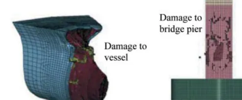
Recently highly sophisticated numerical FEM simula-tions of ship collisions using the interaction between master
F = Km ◊v
Fig. 4. Collision tests by Woisin
Fig. 5. Dynamic impact force plotted against time after Woisin
Fig. 6. Equivalent static impact forces plotted against ship size after Svensson
Fig. 7. Impact forces plotted against ship size after Knott
and slave surfaces to simulate a collision between a ship’s bow and a concrete bridge pier have been carried out by Tongji University, Shanghai, China [9].
Fig. 9 shows the typical calculated dynamic impact forces for a head-on collision of a 50 000 tonne bulk car-rier against a rigid wall plotted against time, compared with the estimated equivalent static loads from the various formulas mentioned above. Naturally, the simplified code equations can give only rough estimations of impact loads. The AASHTO and Eurocode equivalent loads appear to lie on the safe side when compared with Tongji’s calcu-lated dynamic values, whereas the Pedersonequation re-sults in values about double those.
The Tongji calculations have also shown that the col-lision against the elastic foundation on piles, see Fig. 10, reduces the peak value of the collision force by about 50 % compared to that against a rigid wall, Fig. 11.
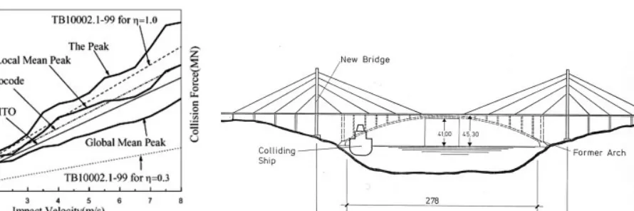
The discussion surrounding how to determine the im-pact forces from ship collision against bridge piers has not yet been finally settled. If equivalent static loads on the bridge piers are used to simplify their sizing, it is question-able as to which mean should be used: the absolute peak value, the local mean peak or the global mean value, Fig. 12. A comparison of these different peaks as calculated by
Tongji University and the equivalent static loads from AASHTO and Eurocode is given in Fig. 13. Please note that the AASHTO formula uses the global mean value over time corresponding to the average force from Fig. 5. In addition, the different structures of ships’ hulls mean that single equations can only approximate the impact load; one for-mula cannot cover all types. The ± 50 % scatter of impact forces as indicated in Fig. 6 still gives a realistic scenario. The best-possible calculation of impact forces today would use a dynamic numerical FEM simulation similar to the Tongji University approach outlined above, taking into account the structure of the ship’s hull as well as the structural details of the collision structure. In addition, the forces and stresses in the pier and the piles during the full impact time should be investigated. Equivalent Fig. 8. Impact forces after Knott
Fig. 9. Collision forces plotted against time by Tongji Univer-sity, Shanghai
Fig. 10. FEM model after Tongji University, Shanghai
Fig. 11. Collision force on rigid and elastic pier after Tongji University
static loads could be determined from the principal de-sign stresses.
3 Protective structures 3.1 General
The following options are available for protecting bridges and other structures against ship collision:
– place out of reach on shore
– deflect ship by artificial islands or guide structures – make piers strong enough to withstand direct collisions
Examples of all these types of protection are given be-low.
3.2 Out of reach
The safest way of protecting piers from ship collisions is to place them out of reach on land. The additional costs for an increased span length may well be offset by savings on pier protection. In case of an arch bridge this means that the arch
itself also has to be out of the ship’s reach as demonstrated by the collapse of the Tjörn Bridge in Sweden due to ship collision, Figs. 14 and 15. The new, cable-stayed Tjörn Bridge, see Figs. 14 and 16, has a main span of 366 m, increased from the 217 m of the original arch, and a minimum naviga-tional clearance over the whole length of the main span of 45.3 m [10]. The new Tjörn Bridge cannot therefore be reached by ships anymore.
The Panama Canal is the busiest man-made waterway in the world, Fig. 17. When a second crossing had to be built, the overriding design condition was that the bridge would not in any way hinder shipping. Both piers were securely placed on land at a safe distance from the water, resulting in a main span of 420 m [11]. The navigational clearance permits the passage of the largest ships that can pass through the current and future locks.
In order to place both tower foundations safely on the river banks, the Yang Pu Bridge across Huangpu River in Shanghai, China, was designed with the former world-record main span of 602 m, Figs. 18 and 19 [12].
Fig. 13. Comparison of equivalent loads after Tongji University
Fig. 14. Old and new Tjörn Bridges, Sweden
Fig. 15. Old Tjörn Bridge after ship collision
Fig. 16. New Tjörn Bridge, Sweden
Fig. 17. Second Panama Canal Bridge, Panama
Fig. 18. Yang Pu Bridge, Shanghai, China
Fig. 19. Foundations for Yang Pu Bridge
Both towers for the Stonecutter Bridge in Hong Kong are placed onshore, which results in a new record main span of 1017 m, Fig. 20 [13]. The pile foundations are located close to the water, protected by sea walls, Fig. 21. If a ship were to collide with the sea wall in front of the foundations, the bow would exert lateral pressure on the piles. The amount and distribution of this lateral load is given in Fig. 22.
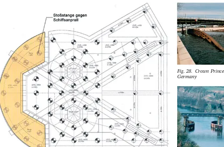
In the harbour at Portsmouth, UK, a viewing tower with a height of about 150 m has been built directly on the waterfront, Fig. 23. An accidental impact by berthing ships cannot be completely ruled out. Various scenarios – in-cluding the approaches of a disabled aircraft carrier and
disabled ferries – have been investigated, Fig. 25, in order to prevent ship’s bows from reaching the tower legs [14].
A crescent-shaped concrete fender has been designed which is connected to the pile cap of the tower by damper elements, Figs. 24 and 25. The energy of a major impact should be absorbed by the plastic deformation of the ves-sel’s hull, local damage to the fender system and the de-formation of the damper elements. The tower foundation is designed to withstand the resulting impact forces.
3.3 Artificial islands
If the water is too wide to be crossed without piers in a navigable channel, it should be investigated as to whether artificial islands are possible. The advantages of such islands are that they provide a high degree of safety and stop a ship gradually, thus limiting the extent of damage to the ship’s hull. If protected against erosion, such islands are virtually maintenance-free and require only minor additional fill after a collision. Their use is often limited insofar as they may not reduce the flow cross-section such that the speed of the current is dangerously increased.
For the Houston Ship Channel Crossing at Baytown, TX, USA, an artificial island was built for the foundation of the one tower that had to be located in shallow water, Fig. 26 [15]. A similar situation exists for the Kap Shui Mun Bridge in Hong Kong: one tower is placed onshore, the
Fig. 21. Stonecutter Bridge, Hong Kong, LAP’s 2nd prize design
V
essel Impact Load (MN)
Preliminary Design Impact Load
Distance from Seawall Cope Line (m) Simplified Horizontal Force Distribution for Ship Impact Loading
20 m
50 m
50 m
20 m
Cope Line
Fig. 22. Stonecutter Bridge, lateral collision pressure on piles
Fig. 23. Portsmouth Tower, UK
other one in shallow water where an artificial island has to provide a minimum clearance of 25 m to passing ships, Fig. 27.
3.4 Guide structures
Guide structures are designed to guide a ship away from the bridge piers or bridge superstructure. They are usually not designed for a head-on collision but instead for the glancing impact of a small or medium-sized vessel.
The Crown Prince Arch Bridge spans the River Spree in the heart of Berlin, Germany, Fig. 28. In order to prevent ships from reaching the arch supports near both riverbanks, steel deflectors were installed. It is interesting to note that the amount of steel required for the deflectors is greater than the amount of steel required for the bridge itself! It may have been more economic to widen the span of the bridge and lo-cate the supports on land, and to use a shallow, constant depth girder completely out of the reach of vessels.
The superstructure of the bridge over the River Neckar near Kirchheim, Germany, had to be replaced with
mini-mum disruption to traffic [17]. The new steel truss beam was therefore launched parallel to the existing bridge on auxiliary piers next to the existing piers, Fig. 29. Guide structures were installed in order to protect these auxiliary piers against ship collision. The fender supports are steel pipes filled with gravel and bored into the underlying rock. The kinetic energy from a glancing impact is absorbed by plastic deformation of the steel pipes. The corresponding large deformation of the guide structures was taken into account by placing them 10 m away from the auxiliary piers. This resulted in a reduction in the navigation width from 40 to 20 m. The permanent piers with the new super-structure are designed to withstand a collision force by themselves, Fig. 30. For that purpose they were vertically post-tensioned into the underlying rock and provided with a 20 cm sacrificial concrete facing.
3.5 Independent protective structures
The centre piers of the aforementioned Zárate Brazo-Largo Bridges in Argentina had to be protected indepen-Fig. 25. Portsmouth Tower, UK, plan on foundation
Fig. 26. Houston Ship Channel Crossing, TX, USA
Fig. 27. Kap Shui Mun Bridge, Hong Kong
Fig. 28. Crown Prince Bridge, Berlin, Germany
Fig. 29. Bridge over Neckar, Kirchheim, Germany, during construction
dently of the bridge against collision with a 25 000 DWT ship, Fig. 31 [3]. Protective islands were not possible due to the great water depth, and since the bridge was already completed, the piers could not be made strong enough to withstand a collision due to the extremely poor soil condi-tions, which required supporting the bridge on piles up to 80 m long. The author therefore proposed independent circular concrete dolphins founded on 70 m long piles with triangular platforms on top to withstand a collision or to guide ships away from the piers, Fig. 32.
However, due to financial reasons the client decided to install floating protection, Fig. 33. The greatest risk of such floating protection lies in its vulnerability to being pushed underwater by the ship’s bow and then being run over, see Fig. 34. Furthermore, all their anchorage devices are sub-ject to severe corrosion attack and are difficult to inspect.
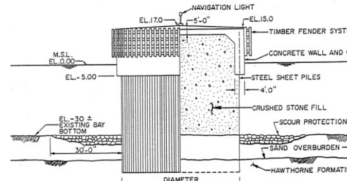
The collapse of the Sunshine Skyway Bridge due to a ship collision, see Fig. 35, has already been mentioned in
section 2.2. For the new Sunshine Skyway Bridge, a pier protection system utilizing a combination of dolphins and island protection was developed [18], see Fig. 36. The dol-phins consist of steel sheet piling 18 m in diameter and a concrete cap, see Fig. 37. They are designed to withstand the collision forces of either a loaded 23 000 DWT or an empty 87 000 DWT bulk carrier. The key to a dolphin’s ability to absorb a major ship collision is to tie the top of the sheet piling rigidly to the concrete cap and to weld to-gether the sheet steel pile interlocks. The dolphins are sac-rificial, i.e. after a major collision the cell would be dam-aged beyond repair and would have to be replaced.
The main span of the Rosario-Victoria Crossing over the River Paraná in Argentina comprises a cable-stayed bridge spanning 350 m [19]. All piers in the river are supported on pile foundations about 30 m deep, Fig. 38. The critical design ship load is 43 000 DWT and a speed of 4.6 m/s, resulting in an impact force of 118 MN in accord-Fig. 31. Zarate Brazo-Largo Bridge,
Argentina
Fig. 32. Zarate Brazo-Largo Bridge, proposed protection
Fig. 33. Zarate Brazo-Largo Bridge, floating protection
ance with AASHTO [6] (228 MN after Pederson [7]). Taking into account a variation in the water level of up to 6 m and local scour of up to 12 m, the total exposed length of piles could reach up to 42 m. With this specific geo-technical and hydraulic situation the foundations them-selves could not be designed to withstand the high impact forces economically within the elastic range. Independent defence structures, designed as sacrificial structures by
ex-ploiting their plastic capacities, were the appropriate solu-tion, Fig. 39.
The protective structures adopted consist of a con-crete platform supported on concon-crete-filled steel piles 2 m in diameter located 17.50 m clear of the bridge foundation in order to permit the high deflections resulting from plas-tic hinges, Fig. 40. The plasplas-tic rotational capacity of the concrete-filled piles was confirmed by tests, Fig. 41. Fig. 35. Sunshine Skyway Bridge,
Tampa, FL, USA, collapsed bridge
Fig. 36. Sunshine Skyway Bridge, dolphin protection
Fig. 37. Sunshine Skyway Bridge, dolphin details
Fig. 39. Rosario-Victoria Bridge, independent protection Fig. 38. Rosario-Victoria Bridge,
Argentina
+5.5 IGM MLW
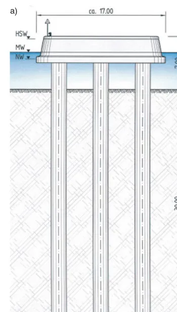
It is well known that not only the main span of a bridge but also the side spans have to be protected against ship collisions, as shown in the case of the Ben-jamin Harrison Bridge, USA, Fig. 42. This experience had to be taken into account for the cable-stayed steel composite pedestrian bridge across the River Rhine be-tween Kehl, Germany, and Strasbourg, France, Fig. 43 [20].
The bridge main foundations can themselves with-stand the impact forces of a ship collision. However, since part of the bridge superstructure extends down to the river-banks, the side spans had to be protected against ship colli-sion by independent structures. For this purpose, indepen-dent impact collision protection supported on three piles was placed upstream, see Fig. 44a. Downstream, concrete-filled steel pipes were considered sufficient, see Fig. 44b. Fig. 42. Ship collision with side span
of Benjamin Harrison Bridge, USA
Fig. 43. Rhine Bridge Kehl, Germany,
Side Span Protection Fig. 44. Bridge over Rhine, Kehl, a) up-stream protection, b) downup-stream protection
Fig. 45. 2nd Orinoco Bridge, Venezuela
Fig. 47. Galata Bridge, Istanbul, Turkey Fig. 46. 2nd Orinoco Bridge, independent pier protection
Two composite cable-stayed bridges for road and rail with main spans of 300 m each form the Second Crossing of the River Orinoco currently under construction in Vene-zuela, Fig. 45 [21]. The piers will be protected against ship collision by independent concrete beams supported on piles, arranged around the actual foundations, see Fig. 46.
3.6 Strong piers
Another way of protecting piers against ship collision in deep water is to make them strong enough to withstand the collision forces by themselves. The vertical loads on the foundations from the bridge weight assist considerably in designing the foundations to withstand horizontal impact loads. For foundations on solid rock not too deep, this type of design can be more economical than designing indepen-dent protective structures without the benefit of the bridge’s dead weight. Since these foundations are rigid, the ship’s kinetic energy mainly has to be absorbed by the ship’s hull and can therefore lead to more damage to the ship than to the sacrificial independent protection, which absorbs the ship’s energy more gently through plastic deformations with large deflections.
In 1981 the Newport Suspension Bridge at Rhode Is-land, USA, was struck head-on by a fully loaded 45 000 DWT tanker. The ship’s bow was shortened by about 3.5 m,
see Fig. 2, but the pier suffered only superficial damage as shown in Fig. 3. The steel H-pile foundations were also strong enough to prevent any permanent displacement of the pier.
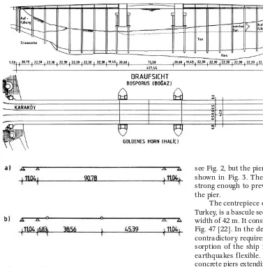
The centrepiece of the new Galata Bridge in Istanbul, Turkey, is a bascule section with a clear span of 80 m and a width of 42 m. It consists of four orthotropic deck bascules, Fig. 47 [22]. In the design of the bascule bridge piers, two contradictory requirements had to be fulfilled: for the ab-sorption of the ship impact they had to be stiff, and for earthquakes flexible. This was achieved by using hollow concrete piers extending down to the bottom of the Golden Horn, where they are founded on 32 m long piles, see Fig. 48. The piers are designed for a head-on collision with a force of 40 MN.
Of course, the steel bascules of the bridge cannot them-selves withstand a ship collision, should a ship run into them while closed. Two governing scenarios were investi-gated, Fig. 49:
– The formation of a plastic hinge in front of a pier in ad-dition to a central plastic hinge.
– The loss of a bascule section between the two hinges. Both scenarios did not lead to the loss of the another bascule or the rear arm with the counterweight and were thus considered acceptable local failures.
The foundations of the towers for the Helgeland Bridge in Norway consist of solid rectangular piers extending max. 32 m down to solid rock, Figs. 50 and 51 [23]. They are designed for an impact force of 54 MN.
The cable-stayed Uddevalla Bridge in Sweden has a main span of 414 m, Fig. 52. Whereas the north tower could be founded on an island, unreachable for ships, the south tower had to be founded on piles in the high-water flood plain, see Fig. 52. This exposed foundation is designed for a collision force of 70 MN in the direction of ship’s travel and for 35 MN in the transverse direction, Fig. 53 [24].
The cable-stayed My Thuan Bridge across the River Mekong in Vietnam is founded on deep piles up to 100 m long, Fig. 54 [25]. Due to scour, the water depth may vary from 16 to 25 m. In the downstream direction the founda-tions had to be designed for a collision force of 32 MN, Fig. 48. Galata Bridge, plan and longitudinal section
determined by the AASHTO Guide Specification. Because of the very difficult design conditions, the pile cap was en-larged by adding deflectors upstream and downstream. In case of a collision, part of the ship’s kinetic energy is ab-sorbed by the hull’s deformation and the crushing of the pile cap deflectors, Fig. 55.
The remaining part of the collision energy is resisted elastically by the piles. Provisions were made in the design for strengthening the foundations to withstand the impact of larger vessels in the future, which may cause a down-stream collision force of up to 39 MN.
4 Conclusion
With growing traffic requirements and the resulting increase in the construction of major bridges across large expanses of water, especially in China, the protection of bridge piers against ship collision is becoming more and more impor-tant. The current state of the art for the two most important considerations in this regard, the determination of impact forces and the structural design of collision protection, is outlined here, based on 25 years of experience gained by the author and his firm Leonhardt, Andrä & Partner in dealing with these problems.
Acknowledgements
The author wishes to thank Prof. Xiang Haifanof Tongji University, Shanghai, China, who provided Reference 9 and to the authors of this paper, Wang Junjie,Yan Hai-quan,Chen Chengand Ou Bifeng, who consented to the use of their findings and figures in this paper.
References:
[1] Minorsky, V.U.: An Analysis of Ship Collision with Refer-ence to Protection of Nuclear Power Plants. Journal of Ship Research 3 (1959).
Fig. 50. Helgeland Bridge, Norway Fig. 51. Helgeland Bridge, construction of solid foundations
Fig. 52. Uddevalla Bridge, Sweden
Fig. 53. Uddevalla Bridge, elevation
Fig. 54. My Thuan Bridge, Vietnam
[2] Woisin, G.: Die Kollisionsversuche der GKSS (The Colli-sion Tests of the GKSS). Jahrbuch der Schiffbautechnischen Gesellschaft, Vol. 17, 1976, Berlin, Heidelberg, New York, pp. 465–487.
[3] Saul, R., Svensson, H.: Zum Schutz von Brückenpfeilern gegen Schiffsanprall (On the Protection of Bridge Piers against Ship Collision). Die Bautechnik 58 (1981), Vol. 10, pp. 326– 335, Vol. 11, 374–388.
[4] Saul, R., Svensson, H.: On the Theory of Ship Collision against Bridge Piers. IABSE Proceedings P-51/82, pp. 29–40. [5] Saul, R., Svensson, H.: Ship Collision with Bridges and
Off-shore Structures. Colloquium Copenhagen 1983, Introductory Report, pp. 165–179.
[6] AASHTO 1991. Guide Specification and Commentary for Vessel Collision Design of Highway Bridges. American Associ-ation of State Highway and TransportAssoci-ation Officials, Washing-ton D.C.
[7] Pederson, P.T.: Ship Impacts: Bow Collisions. Proceedings from the Third International Symposium on Structural Crashworthiness and Failure, University of Liverpool, 1993. [8] Larsen, O.D.: Ship Collision with Bridges. IABSE Structural
Engineering Documents 4, 1993.
[9] Wang, J., et al.: Comparison of Design Formula of Ship Col-lision for Bridges based on FEM Simulations. (in Chinese) Journal of Highway and Transportation Research and Devel-opment, Vol. 23, No. 2, pp. 68–73.
[10] Brodin, S.: Tjörn Bridge. Swedish National Road Adminis-tration, 1984, ISBN 91-7810-124-7.
[11] Humpf, K.: Puente Centenario Crossing the Panama Canal. 3rd New York City Bridge Conference, September 12–13, 2005.
[12] Yang Xiao-lin: Yang Pu Bridge. Shanghai Scientific and Technological Publishing House, 1994. ISBN 7-5428-0941-5/J1. [13] Stonecutters Bridge Design Competition – Stage 2.
Docu-mentation by Leonhardt, Andrä & Partner, 2000.
[14] Andrä, H.-P., Dietsch, B., Sandner, D.: Formfindung und Entwurfsplanung des Spinaker Tower in Portsmouth (Shaping and Designing the Spinaker Tower in Portsmouth). Bautechnik 81 (2004), No. 7, pp. 507–515.
[15] Svensson, H., Lovett, T.G.: The twin cable-stayed composite Bridge at Baytown, Texas. IABSE Symposium Brussels 1990, pp. 317–322.
[16] Saul, R., Lovett, T., Hopf, S.: Design and Construction of the Kap Shui Mun Bridge at Hong Kong. Proceedings of the International HKCEC Bridge Conference „Bridges into the 21st Century“ 2-5 October 1995, Hong Kong.
[17] Saul, R. Hanke, R., Kusch, G.: Die neue Neckarbrücke zwischen Kirchheim und Gemrigheim. Stahlbau 67 (1998), No. 1, pp. 36–45.
[18] Knott, M.: Pier Protection System for the Sunshine Sky-way Bridge Replacement. Proceedings at 3rd Annual Interna-tional Bridge Conference, Pittsburgh, PA, 1986.
[19] Saul, R., Humpf, K., Patsch, A.: The Rosario-Victoria cable-stayed Bridge across the River Paraná in Argentina and its Ship Impact Protection System. Proceedings of the First Interna-tional Conference on Steel and Composite Structures Pusan, Korea, June 2001, pp. 1011–1018.
[20] Morgenthal, G., Saul, R.: Die Geh- und Radwegbrücke Kehl – Strasbourg. Stahlbau 74 (2005), No. 2, pp. 121–125. [21] Humpf, K., Lustgarten, M.: Venezuela’s Second Orinoco
Crossing. The Magazine of Engineers Australia, August 2005, pp. 32–34.
[22] Saul, R., Zellner, W.: The new Galata Bascule Bridge at Is-tanbul. IABSE Symposium Leningrad 1991, pp. 557–562. [23] Svensson, H., Jordet, E.: The concrete cable-stayed
Helge-land Bridge in Norway. Civil Engineering, Vol. 114, No. 2, May 1996, pp. 54–63.
[24] Uddevallabron, Den vackraste genvägen. Vägverket, ISBN: 91-88250-42-3.
[25] Clark, J.: Mekong milestone. Bridge design & engineering First Quarter 2000, pp. 50–59
Keywords:bridges; ship collision; impact forces; protective struc-tures; foundations; pile tests
Author:
![Fig. 26 [15]. A similar situation exists for the Kap Shui Mun](https://thumb-ap.123doks.com/thumbv2/123dok/3946011.1889431/5.651.304.554.378.613/fig-similar-situation-exists-kap-shui-mun.webp)