Cloud Networking
Understanding Cloud-based
Data Center Networks
Gary Lee
AMSTERDAM • BOSTON • HEIDELBERG • LONDON NEW YORK • OXFORD • PARIS • SAN DIEGO SAN FRANCISCO • SINGAPORE • SYDNEY • TOKYO
Designer:Russell Purdy
Morgan Kaufmannis an imprint of Elsevier 225 Wyman Street, Waltham, MA 02451 USA
Copyright#2014 Gary Lee. Published by Elsevier Inc. All rights reserved.
No part of this publication may be reproduced or transmitted in any form or by any means, electronic or mechanical, including photocopying, recording, or any information storage and retrieval system, without permission in writing from the publisher. Details on how to seek permission, further information about the Publisher’s permissions policies and our
arrangements with organizations such as the Copyright Clearance Center and the Copyright Licensing Agency, can be found at our website:www.elsevier.com/permissions.
This book and the individual contributions contained in it are protected under copyright by the Publisher (other than as may be noted herein).
Notices
Knowledge and best practice in this field are constantly changing. As new research and experience broaden our understanding, changes in research methods or professional practices, may become necessary. Practitioners and researchers must always rely on their own experience and knowledge in evaluating and using any information or methods described herein. In using such information or methods they should be mindful of their own safety and the safety of others, including parties for whom they have a professional responsibility.
To the fullest extent of the law, neither the Publisher nor the authors, contributors, or editors, assume any liability for any injury and/or damage to persons or property as a matter of products liability, negligence or otherwise, or from any use or operation of any methods, products, instructions, or ideas contained in the material herein.
Library of Congress Cataloging-in-Publication Data Lee, Gary Geunbae,
1961-Cloud networking : developing cloud-based data center networks / Gary Lee. pages cm
ISBN 978-0-12-800728-0 1. Cloud computing. I. Title.
QA76.585.L434 2014 004.67’82–dc23
2014006135 British Library Cataloguing-in-Publication Data
A catalogue record for this book is available from the British Library.
ISBN: 978-0-12-800728-0
Printed and bound in the United States of America
14 15 16 17 18 10 9 8 7 6 5 4 3 2 1
About the Author
Gary Lee has been working in the semiconductor industry since 1981. He began his career as a transistor-level chip designer specializing in the development of high-performance gallium arsenide chips for the communication and computing markets. Starting in 1996 while working for Vitesse®Semiconductor, he led the development of the world’s first switch fabric chip set that employed synchronous high-speed serial interconnections between devices, which were used in a variety of communi-cation system designs and spawned several new high performance switch fabric product families. As a switch fabric architect, he also became involved with switch chip designs utilizing the PCI Express interface standard while working at Vitesse and at Xyratex®, a leading storage system OEM. In 2007, he joined a startup com-pany called Fulcrum Microsystems who was pioneering low latency 10GbE switch silicon for the data center market. Fulcrum was acquired by Intel Corporation in 2011 and he is currently part of Intel’s Networking Division. For the past 7 years he has been involved in technical marketing for data center networking solutions and has written over 40 white papers and application notes related to this market segment. He received his BS and MS degrees in Electrical Engineering from the University of Minnesota and holds 7 patents in several areas including transistor level semicon-ductor design and switch fabric architecture. His hobbies include travel, playing gui-tar, designing advanced guitar tube amps and effects, and racket sports. He lives with his wife in California and has three children.
Over the last 30 years I have seen many advances in both the semiconductor industry and in the networking industry, and in many ways these advances are intertwined as network systems are dependent upon the constant evolution of semiconductor tech-nology. For those of you who are interested, I thought I would start by providing you with some background regarding my involvement in the semiconductor and net-working industry as it will give you a feel of from where my perspective originates. When I joined the semiconductor industry as a new college graduate, research labs were still trying to determine the best technology to use for high performance logic devices. I started as a silicon bipolar chip designer and then quickly moved to Gallium Arsenide (GaAs), but by the 1990s I witnessed CMOS becoming the dom-inant semiconductor technology in the industry. About the same time I graduated from college, Ethernet was just one of many proposed networking protocols, but by the 1990s it had evolved to the point where it began to dominate various network-ing applications. Today it is hard to find other networknetwork-ing technologies that even compete with Ethernet in local area networks, data center networks, carrier networks, and modular system backplanes.
In 1996 I was working at Vitesse Semiconductor and after designing GaAs chips for about 12 years I started to explore ideas of utilizing GaAs technology in new switch fabric architectures. At the time, silicon technology was still lagging behind GaAs in maximum bandwidth capability and the switch fabric chip architectures that we know today did not exist. I was lucky enough to team up with John Mullaney, a network engineering consultant, and together we developed a new high-speed serial switch architecture for which we received two patents. During this time, one name continued to come up as we studied research papers on switch fabric architecture. Nick McKeown and his students conducted much of the basic research leading to today’s switch fabric designs while he was a PhD candidate at the University of Cal-ifornia at Berkeley. Many ideas from this research were employed in the emerging switch fabric architectures being developed at that time. By the late 1990s CMOS technology had quickly surpassed the performance levels of GaAs, so our team at Vitesse changed course and started to develop large CMOS switch fabric chip sets for a wide variety of communications markets. But we were not alone.
From around 1996 until the end of the telecom bubble in the early 2000s, 20 to 30 new and unique switch fabric chip set designs were proposed, mainly for the boom-ing telecommunications industry. These designs came from established companies like IBM® and from startup companies formed by design engineers who spun out of companies like Cisco®and Nortel. They also came from several institutions like Stanford University and the University of Washington. But the bubble eventually burst and funding dried up, killing off most of these development efforts. Today there are only a few remnants of these companies left. Two examples are Sandburst and Dune Networks which were acquired by Broadcom®.
At the end of this telecom boom cycle, several companies remaining in the switch fabric chip business banded together to form the Advanced Switching Interconnect Special Interest Group (ASI-SIG) which was led by Intel®. It’s goal was to create a standard switch fabric architecture for communication systems built around the PCI Express interface specification. I joined the ASI-SIG as the Vitesse representative on the ASI Board of Director’s midway through the specification development and it quickly became clear that the spec was over-ambitious. This eventually caused Intel and other companies slowly pulled back until ASI faded into the sunset. But for me this was an excellent learning experience on how standards bodies work and also gave me some technical insights into the PCI Express standard which is widely used in the computer industry today.
Before ASI completely faded away, I started working for Xyratex, a storage company looking to expand their market by developing shared IO systems for servers based on the ASI standard. Their shared IO program was eventually put on hold so I switched gears and started looking into SAS switches for storage applications. Although I only spent 2 years at Xyratex, I did learn quite a bit about Fibre Channel, SAS, and SATA storage array designs, along with the advantages and limitations of flash based storage from engineers and scientists who had spent years working on these technologies even before Xyratex spun out of IBM.
Throughout my time working on proprietary switch fabric architectures, my counterparts in the Ethernet division at Vitesse would poke at what we were doing and say “never bet against Ethernet.” Back in the late 1990s I could provide a list of reasons why we couldn’t use Ethernet in telecom switch fabric designs, but over the years the Ethernet standards kept evolving to the point where most modular commu-nication systems use Ethernet in their backplanes today. One could argue that if the telecom bubble hadn’t killed off so many switch fabric startup companies, Ethernet would have.
The next stop in my career was my third startup company called Fulcrum Microsystems, which at the time I joined had just launched its latest 24-port 10GbE switch chip designed for the data center. Although I had spent much of my career working on telecom style switch fabrics, over the last several years I have picked up a lot of knowledge related to data center networking and more recently on how large cloud data centers operate. I have also gained significant knowledge about the various Ethernet and layer 3 networking standards that we continue to support in our switch silicon products. Intel acquired Fulcrum Micro-systems in September 2011, and as part of Intel, I have learned much more about server virtualization, rack scale architecture, microserver designs, and software-defined networking.
CHAPTER
Welcome to Cloud
Networking
1
Welcome to a book that focuses on cloud networking. Whether you realize it or not, the “Cloud” has a significant impact on your daily life. Every time you check some-one’s status on Facebook®, buy something on Amazon®, or get directions from Google®Maps, you are accessing computer resources within a large cloud data cen-ter. These computers are known as servers, and they must be interconnected to each other as well as to you through the carrier network in order for you to access this information. Behind the scenes, a single click on your part may spawn hundreds of transactions between servers within the data center. All of these transactions must occur over efficient, cost effective networks that help power these data centers.
This book will focus on networking within the data center and not the carrier net-works that deliver the information to and from the data center and your device. The subject matter focuses on network equipment, software, and standards used to create networks within large cloud data centers. It is intended for individuals who would like to gain a better understanding of how these large data center networks operate. It is not intended as a textbook on networking and you will not find deep protocol details, equa-tions, or performance analysis. Instead, we hope you find this an easy-to-read overview of how cloud data center networks are constructed and how they operate.
INTRODUCTION
Around the world, new cloud data centers have been deployed or are under construc-tion that can contain tens of thousands and in some cases hundreds of thousands of servers. These are sometimes called hyper-scale data centers. You can think of a server as something similar to a desktop computer minus the graphics and keyboard but with a beefed up processor and network connection. Its purpose is to “serve” information to client devices such as your laptop, tablet, or smart phone. In many cases, a single web site click on a client device can initiate a significant amount of traffic between servers within the data center. Efficient communication between all of these servers, and associated storage within the cloud data center, relies on advanced data center networking technology.
In this chapter, we will set the stage for the rest of this book by providing some basic networking background for those of you who are new to the subject, along with providing an overview of cloud computing and cloud networking. This background information should help you better understand some of the topics that are covered later
in this book. At the end of this chapter, we will describe some of the key characteristics of a cloud data center network that form the basis for many of the chapters in this book.
NETWORKING BASICS
This book is not meant to provide a deep understanding of network protocols and standards, but instead provides a thorough overview of the technology inside of cloud data center networks. In order to better understand some of the subject presented in this book, it is good to go over some basic networking principals. If you are familiar with networking basics, you may want to skip this section.
The network stack
Almost every textbook on networking includes information on the seven-layer Open Systems Interconnect (OSI) networking stack. This model was originally developed in the 1970s as part of the OSI project that had a goal of providing a common network standard with multivendor interoperability. OSI never gained acceptance and instead Transmission Control Protocol/Internet Protocol (TCP/IP) became the dominant internet communication standard but the OSI stack lives on in many technical papers and textbooks today.
Although the networking industry still refers to the OSI model, most of the protocols in use today use fewer than seven layers. In data center networks, we refer to Ethernet as a layer 2 protocol even though it contains layer 1 and layer 2 components. We also generally refer to TCP/IP as a layer 3 protocol even though it has layer 3 and layer 4 components. Layers 5-7 are generally referred to in the industry as application layers. In this book, we will refer to layer 2 as switching (i.e., Ethernet) and layer 3 as routing (i.e., TCP/IP). Anything above that, we will refer to as the application layer.Figure 1.1
shows an example of this simplified model including a simple data center transaction.
Application
In this simplified example, the sender application program presents data to the TCP/IP layer (sometimes simply referred to as layer 3). The data is segmented into frames (packets) and a TCP/IP header is added to each frame before presenting the frames to the Ethernet layer (sometimes simply referred to as layer 2). Next, an Ethernet header is added and the data frames are transmitted to the receiving device. On the receive side, the Ethernet layer removes the Ethernet header and then the TCP/IP layer removes the TCP/IP header before the received frames are reassembled into data that is presented to the application layer. This is a very simplified explanation, but it gives you some background when we provide more details about layer 2 and layer 3 protocols later in this book.
As an analogy, think about sending a package from your corporate mail room. You act as the application layer and tell your mail room that the gizmo you are hold-ing in your hand must be shipped to a given mail station within your corporation that happens to be in another city. The mail room acts as layer 3 by placing the gizmo in a box, looking up and attaching an address based on the destination mail station num-ber, and then presenting the package to the shipping company. Once the shipping company has the package, it may look up the destination address and then add its own special bar code label (layer 2) to get it to the destination distribution center. While in transit, the shipping company only looks at this layer 2 label. At the des-tination distribution center, the local address (layer 3) is inspected again to determine the final destination. This layered approach simplifies the task of the layer 2 shipping company.
Packets and frames
Almost all cloud data center networks transport data using variable length frames which are also referred to as packets. We will use both terms in this book. Large data files are segmented into frames before being sent through the network. An example frame format is shown inFigure 1.2.
The data is first encapsulated using a layer 3 header such as TCP/IP and then encap-sulated using a layer 2 header such as Ethernet as described as part of the example in the last section. The headers typically contain source and destination address informa-tion along with other informainforma-tion such as frame type, frame priority, etc. In many cases, checksums are used at the end of the frame to verify data integrity of the entire frame. The payload size of the data being transported and the frame size depend on the protocol. Standard Ethernet frames range in size from 64 to 1522 bytes. In some cases jumbo frames are also supported with frame sizes over 16K bytes.
L2 header
L3 header
Variable length
data Checksum
FIGURE 1.2
Example frame format.
Network equipment
Various types of network equipment can be used in cloud data centers. Servers con-tain network interface cards (NICs) which are used to provide the server CPU(s) with external Ethernet ports. These NICs are used to connect the servers to switches in the network through data cables. The term switch is generally used for equipment that forwards data using layer 2 header information. Sometimes, an Ethernet switch may also be referred to as an Ethernet bridge and the two terms can be used interchange-ably. The term router is generally used for equipment that forwards data using layer 3 header information. Both switches and routers may be used within large cloud data center networks, and, in some cases, Ethernet switches can also support layer 3 routing.
Interconnect
In the data center, servers are connected to each other, connected to storage, and con-nected to the outside network through switches and routers. These connections are made using either copper or optical cabling. Historically, copper cabling has been a lower-cost solution, while optical cabling has been used when higher bandwidth and/ or longer cabling distances are required. For example, shorter, copper cabling may be used as a connection between the servers and switches within a rack, and high band-width optical cabling may be used for uplinks out of the rack in order to span longer distances. We will provide more information on cable types later in this chapter.
WHAT IS A CLOUD DATA CENTER?
In the early days of the world wide web (remember that term?) data was most likely delivered to your home computer from a room full of servers in some sort of corpo-rate data center. Then, the internet exploded. The number of people accessing the web grew exponentially as did the number of web sites available as well as the aver-age data download sizes. Popular web service companies such as Google and Amazon needed to rapidly expand their data centers to keep up with demand. It quickly got to the point where they needed to erect large dedicated server warehouses that are today known as cloud data centers.
The term “cloud” started emerging around the same time wireless handheld devices started to become popular in the marketplace. When accessing the web via a wireless handheld device, it seems like you are pulling data out of the clouds. It is natural, then, that the data centers providing this information should be called cloud data centers. Today, it appears that everyone is jumping on the “cloud” band-wagon with all kinds of cloud companies, cloud products, and cloud services entering the market.
efficiency and cost of operations have become critical. Because of this, some cloud data centers have been erected near cheap electrical power sources, such as hydro-electric dams, or in colder climates to help reduce cooling costs. Some companies, such as Microsoft®, are building modular data centers using pods, which are self-contained server storage and networking modules the size of a shipping con-tainer. These modules are trucked in, stacked up, and connected to power, cooling, and networking. Other data centers use server racks as the basic building block and contain rows and rows of these racks. No matter what the structure, networking is an important part of these large cloud data center networks.
A recent Cisco®white paper entitledCisco Global Cloud Index: Forecast and Methodology, 2012–2017provides some interesting insights into cloud data centers. They predict that global IP data center traffic will grow by 25% each year at least through 2017. They also predict that by 2017 over two thirds of all data center traffic will be based in the cloud and 76% percent of this traffic will be between devices within the cloud data center as opposed to data traveling in and out of the data center. They also predict that server virtualization (multiple virtual servers running on a physical server) will have a large impact on cloud data center networks. They use the ratio of the total number of server workloads divided by the total number of phys-ical servers and predict that, by 2017, this ratio will be above 16 versus about 2-3 for traditional data centers today. In other words, server virtualization (which will be discussed later in this book) will continue to be a dominant feature in cloud data cen-ters. All of these factors have an impact on how large cloud data centers are designed and operated along with how cloud data center networking is implemented.
WHAT IS CLOUD NETWORKING?
With cloud data centers utilizing racks of servers or stacks of data center pods, net-working all of these components together becomes a challenge. Cloud data center administrators want to minimize capital and operating expenses which include net-work adapter cards, switches, routers, and cabling. Ethernet has emerged as the low-cost layer 2 network for these large data centers, but these networks have special requirements that are different from traditional corporate Local Area Networks (LANs) or enterprise data center networks. We will call this type of network a “cloud data center network” throughout the rest of this book, and we will describe many of the key differences that set these networks apart from traditional enterprise networks.
CHARACTERISTICS OF CLOUD NETWORKING
Most cloud data centers have special requirements based on maximizing perfor-mance while minimizing cost. These requirements are reflected in their network designs which are typically built using Ethernet gear that takes advantage of Ethernet economies of scale while at the same time providing high bandwidth and features
tailored for the data center. In this section, we will provide some background on these trends, including information on Ethernet cabling technology, along with an over-view of network virtualization, network convergence, and scalability requirements.
Ethernet usage
When I started working on switch fabric chip designs in the mid-1990s, Ethernet was considered a LAN technology and, for critical telecom applications, an unreliable transport mechanism that would drop packets under heavy congestion. But it was always the lowest cost networking technology, mainly due to its wide deployment and use of high volume manufacturing. Ethernet has come a long way since then and many features and improvements have been added to the Ethernet specification over the last 10 years. Today, Ethernet is truly everywhere, from interconnecting the boards within network appliances to use in long distance carrier network links.
In the data center, Ethernet has become the standard network technology and this book will cover several of the advanced Ethernet features that are useful for large cloud data center networks. One of the advantages of Ethernet is the low-cost cabling tech-nology that is available. You may be familiar with the classic Category 5 (Cat5) copper cabling that is used to make a wired Ethernet connection between a computer and a wall jack. This type of cabling has been used extensively in data centers for 1Gbit Ethernet (1GbE) connections due to its low cost and long reach. Now that data centers are adopting 10Gbit Ethernet (10GbE), a new interconnect standard called 10GBase-T has become available, which allows the use of low-cost Category 6 (Cat6) copper cables for distances up to 100 m. This is very similar to Cat5 and is much lower cost than optical cabling at these distances. One issue with 10GBase-T is the high latency it introduces compared to the low cut-through latencies available in new data center switches. It can also add power and cost to Ethernet switches compared to some alternative interface options. Because of this, many cloud data center server racks are interconnected using what is called direct attach copper cabling, which can support 10GbE and 40GbE connections for distances up to a few meters with reasonable cost. For longer distances or higher bandwidths, there are some interesting low-cost optical technologies coming into the market which will be discussed further inChapter 11.
Virtualization
money for both the hosting data center as well as the consumer. We will provide more information on server virtualization inChapter 6.
Virtualization is also becoming important in the cloud data center network. New tunneling protocols can be used at the edge of the network that effectively provide separate logical networks for services such as public cloud hosting where multiple corporations may each have hundreds of servers or virtual machines that must com-municate with each other across a shared physical network. For this type of applica-tion, these multitenant data centers must provide virtual networks that are separate, scalable, flexible, and secure. We will discuss virtual networking inChapter 7.
Convergence
Cloud data centers cannot afford to provide separate networks for storage and data because this would require a large number of separate switches and cables. Instead, all data and storage traffic is transported through the Ethernet network. But storage traffic has some special requirements because it usually contains critical data and cannot be dropped during periods of high congestion in the network. Because of this, data center bridging standards have been developed for use within Ethernet switches that can provide lossless operation and minimum bandwidth guarantees for storage traffic. We will provide further information on data center bridging inChapter 5.
Scalability
Data center networks must interconnect tens of thousands of servers including stor-age nodes and also provide connections to the outside carrier network. This becomes an architectural challenge when the basic network building blocks are integrated cir-cuits with only up to 100 ports each. These building blocks must be used to create data center networks that can be easily scaled to support thousands of endpoints while at the same time providing low latency along with minimal congestion. There are many ways to interconnect these integrated circuits to form scale-out data center networks and these will be covered inChapters 3and4.
One hardware initiative that is helping to improve server density and, therefore, increase data center scaling is the Open Compute Project that is being sponsored by Facebook along with several Original Equipment Manufacturers (OEMs) and Orig-inal Design Manufactures (ODMs). The mission statement from the opencompute. org web site is:
The Open Compute Project Foundation is a rapidly growing community of engi-neers around the world whose mission is to design and enable the delivery of the most efficient server, storage and data center hardware designs for scalable com-puting. We believe that openly sharing ideas, specifications and other intellectual property is the key to maximizing innovation and reducing operational complexity in the scalable computing space. The Open Compute Project Foundation provides a structure in which individuals and organizations can share their intellectual property with Open Compute Projects.
One of their goals is to create rack scale architectures that provide higher density server shelves by utilizing 2100wide racks instead of the traditional 1900racks. This
will require some higher density networking solutions as well as including rack scale architectures which we will discuss inChapters 4and11.
Software
Large cloud data center networks are set up, configured, and monitored using soft-ware. Cloud data center server and storage resources may also be set up, configured, and monitored using different sets of software. In many cases, setting up a new tenant in a public cloud requires tight coordination between the network, server, and storage administrators and may take days to complete. In addition, the networking software may be tightly coupled to a given network equipment vendors hardware, making it very difficult to mix and match equipment from different vendors.
To get around some of these issues and to reduce cost, many cloud data centers are buying lower-cost networking equipment designed to their specifications and built by ODMs in Asia. Google was one of the first companies to do this, and others are following suit. They are also developing their own software which is targeted to their specific needs and doesn’t carry the overhead associated with traditional net-working equipment software. These industry changes are being facilitated by soft-ware defined networking (SDN) initiatives such as OpenFlow. The high-level goal is to provide a central orchestration layer that configures both the network and servers in a matter of minutes instead of days with little risk of human error. It also promises to simplify the networking equipment and make the network oper-ating system hardware agnostic, allowing the use of multiple switch vendors and, therefore, further reducing cost for the data center administrator. We will discuss SDN in more detail inChapter 9.
SUMMARY OF THIS BOOK
This book should give the reader a good overview of all of the different technologies involved in cloud data center networks. InChapter 2, we will go through a history of the evolution of the data center from early mainframe computers to cloud data cen-ters. InChapter 3, we will describe switch fabric architectures at the chip level and how they have evolved based on data center requirements. In Chapter 4, we will move up one level and describe the various types of networking equipment that uti-lize these communication chips and how this equipment is interconnected to form large cloud data center networks. InChapter 5, we will discuss several industry stan-dards that are useful in cloud data center networks and how these stanstan-dards are implemented.Chapter 6goes into server virtualization, focusing on the networking aspects of this technology.Chapter 7provides an overview of network virtualization including some new industry standards that are useful in multitenant data centers.
understanding cloud data center networks andChapter 9 provides information on SDN and how it can be used to configure control and monitor cloud data centers.
Chapter 10is an overview of high performance computing networks. Although this is not generally relevant to cloud data centers today, many of these same technologies may be used in future data center networks. Finally,Chapter 11provides a glimpse into the future of cloud data center networking.
Data Center Evolution—
Mainframes to the Cloud
2
The modern age of computing began in the 1950s when the first mainframe com-puters appeared from companies like IBM®, Univac, and Control Data. Communi-cation with these computers was typically through a simple input/output (I/O) device. If you needed to compute something, you would walk to the computer room, submit your job as a stack of punch cards, and come back later to get a printout of the results. Mainframes later gave way to minicomputers like the PDP-11 from Digital Equipment Corporation (DEC), and new methods of computer networking started to evolve. Local area networks (LANs) became commonplace and allowed access to computing resources from other parts of the building or other parts of the campus. At the same time, small computers were transformed into servers, which “served up” certain types of information to client computers across corporate LANs. Eventually, servers moved into corporate data centers and they evolved from systems that looked like high-performance tower PCs into rack-mounted gear.
When the Advanced Research Projects Agency Network (ARPANET) gave birth to the internet, things started to get interesting. In order to provide web hosting services, dedicated data center facilities full of servers began to emerge. Initially, these data centers employed the same LAN networking gear used in the corporate data centers. By the end of the 1990s, Ethernet became the predominant networking technology in these large data centers, and the old LAN-based networking equipment was slowly replaced by purpose-built data center networking gear. Today, large cloud data center networks are common, and they require high-performance networks with special cloud networking features. This chapter will provide a brief history of the evolution of computer networking in order to give the reader a perspec-tive that will be useful when reading the following chapters in this book.
THE DATA CENTER EVOLUTION
Over the past 50 years or so, access to computer resources has come full circle from dumb client terminals connected to large central mainframes in the 1960s, to distrib-uted desktop computing starting in the 1980s, to handhelds connected to large cen-tralized cloud data centers today. You can think of the handheld device as a terminal receiving data computed on a server farm in a remote cloud data center, much like the terminal connected to the mainframe. In fact, for many applications, data processing is moving out of the client device and into the cloud. This section will provide an
overview of how computer networks have evolved from simple connections with large mainframe computers into today’s hyper-scale cloud data center networks.
Early mainframes
Mainframes were the first electronic computing systems used widely by businesses, but due to their high capital and operating costs, even large business or universities could afford only one computer at a given site. Because of the cost, time sharing became the mode of operation for these large computers. Client communication involved walking over to the computer center with a stack of punch cards or a paper tape, waiting a few hours, and then picking up a printout of the results. Later, teletype terminals were added, allowing users to type in commands and see results on printed paper. Originally, teletypes printed program commands on paper tape, which was manually fed into the computer. Later, teletypes were connected directly to the com-puter using proprietary communication protocols as shown inFigure 2.1. In the late 1960s, CRT terminals were becoming available to replace the teletype.
Minicomputers
In the late 1970s, integrated circuits from companies like Intel®were dramatically reducing the cost and size of the business computer. Companies such as DEC took advantage of these new chips to develop a new class of computing system called the minicomputer. Starting with the PDP-8 and then more famously the PDP-11, busi-nesses could now afford multiple computing systems per location. I can remember walking through Bell Labs in the early 1980s where they were proudly showing a room full of PDP-11 minicomputers used in their research work. These computer rooms are now typically called enterprise data centers.
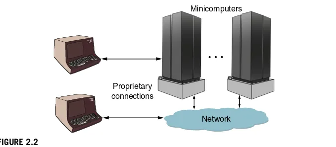
Around this same time, more sophisticated computer terminals were developed, allowing access to computing resources from different locations in the building or campus. By now, businesses had multiple minicomputers and multiple terminals accessing these computers as shown inFigure 2.2. The only way to efficiently connect
Proprietary connection
FIGURE 2.1
Mainframe client terminal connections.
these was to build some sort of Local Area Network (LAN). This spawned a lot of innovation in computer network development which will be discussed in more detail in the next section.
Servers
Around the late 1980s, IT administrators realized that there were certain types of information such as corporate documents and employee records that did not need the computing power of mainframes or minicomputers, but simply needed to be accessed and presented to the client through a terminal or desktop computer. At around the same time, single board computers were becoming more powerful and evolved into a new class of computers called workstations. Soon corporations were dedicating these single board computers to serve up information across their LANs. The age of the compute server had begun as shown inFigure 2.3.
Minicomputers
Network Proprietary
connections
FIGURE 2.2
Minicomputer client terminal connections.
Local area network
Servers
FIGURE 2.3
By the 1990s, almost all business employees had a PC or workstation at their desk connected to some type of LAN. Corporate data centers were becoming more complex with mixtures of minicomputers and servers which were also connected to the LAN. Because of this, LAN port count and bandwidth requirements were increasing rapidly, ushering in the need for more specialized data center networks. Several networking technologies emerged to address this need, including Ethernet and Token Ring which will be discussed in the next sections.
Enterprise data centers
Through the 1990s, servers rapidly evolved from stand-alone, single board com-puters to rack-mounted comcom-puters and blade server systems. Ethernet emerged as the chosen networking standard within the data center with Fibre Channel used for storage traffic. Within the data center, the Ethernet networks used were not much different from the enterprise LAN networks that connected client computers to the corporate data center. Network administrators and network equipment manufac-turers soon realized that the data center networks had different requirements com-pared with the enterprise LAN, and around 2006, the first networking gear specifically designed for the data center was introduced. Around that same time, industry initiatives, such as Fibre Channel over Ethernet (FCoE), were launched with the goal of converging storage and data traffic onto a single Ethernet network in the data center. Later in this chapter, we will compare traditional enterprise data center networks to networks specifically designed for the data center.Figure 2.4shows a LAN connecting client computers to an enterprise data center that employs enter-prise networking equipment.
Cloud data centers
When I was in high school, I remember listening to the Utopiaalbum from Todd Rundgren. This album had one side dedicated to a song called “The Ikon,” which impressed upon me the idea of a central “mind” from which anyone could access any information they needed anytime they needed it. Well, we are definitely headed
Local area network
Enterprise networking
FIGURE 2.4
Enterprise data center networks.
in that direction with massive cloud data centers that can provide a wide variety of data and services to your handheld devices wherever and whenever you need it. Today, whether you are searching on Google, shopping on Amazon, or checking your status on Facebook, you are connecting to one of these large cloud data centers. Cloud data centers can contain tens of thousands of servers that must be con-nected to each other, to storage, and to the outside world. This puts a tremendous strain on the data center network, which must be low cost, low power, and high band-width. To minimize the cost of these data centers, cloud service providers are acquir-ing specialized server boards and networkacquir-ing equipment which are built by Original Design Manufacturers (ODMs) and are tailored to their specific workloads. Face-book has even gone as far as spearheading a new server rack standard called the Open Compute Project that better optimizes server density by expanding to a 21-inch wide rack versus the old 19-inch standard. Also, some cloud data center service providers, such as Microsoft, are using modular Performance Optimized Data center modules (PODs) as basic building blocks. These are units about the size of a shipping con-tainer and include servers, storage, networking, power, and cooling. Simply stack the containers, connect external networking, power, and cooling, and you’re ready to run. If a POD fails, they bring in a container truck to move it out and move a new one in. Later in this chapter, we will provide more information on the types of features and benefits enabled by these large cloud data centers.Figure 2.5is a pic-torial representation showing client devices connected through the Internet to a large cloud data center that utilizes specialized cloud networking features.
Virtualized data centers
Many corporations are seeing the advantage of moving their data center assets into the cloud in order to save both capital and operating expense. To support this, cloud data centers are developing ways to host multiple virtual data centers within their physical data centers. But the corporate users want these virtual data centers to appear to them as private data centers. This requires the cloud service provider to offer isolated, multitenant environments that include a large number of virtual
))))
Cloud networking
Internet
FIGURE 2.5
machines and virtualized networks as shown inFigure 2.6. In this simplified view, we show three tenants that are hosted within a large cloud data center.
Within the physical servers, multiple virtual machines (virtual servers) can be maintained which help maximize data center efficiency by optimizing processing resource utilization while also providing server resiliency. Within the network, tunneling protocols can be used to provide multiple virtual networks within one large physical network. Storage virtualization can also being used to optimize storage per-formance and utilization. In this book, we will not go very deep into storage virtua-lization and only describe virtual machines in the context of data center networking. But we will dive deeper into some of the network tunneling standards that are employed for these multitenant environments.
COMPUTER NETWORKS
In the last section, we went through a brief history of enterprise computing and the evolution toward cloud data centers. We also mentioned local area networking as a key technology development that eventually evolved into purpose-built data center networks. A variety of different network protocols were developed over the last 50 years for both LANs and wide area networks (WANs), with Ethernet emerging as the predominant protocol used in local area, data center, and carrier networks today. In this section, we will provide a brief history of these network protocols along with some information on how they work and how they are used. For completeness, we are including some protocols that are used outside the data center because they provide the reader with a broader view of networking technology. Ethernet will be covered separately in the following section.
Server
Virtual machines
Server
Virtual machines Virtual networks
Tenant 1
Tenant 2
Tenant 3
FIGURE 2.6
The virtualized data center.
Dedicated lines
As you may have guessed, the initial methods used to communicate with mainframe computers were through dedicated lines using proprietary protocols. Each manufac-turer was free to develop its own communication protocols between computers and devices such as terminals and printers because the end customer purchased every-thing from the same manufacturer. These were not really networks per se, but are included in this chapter in order to understand the evolution to true networking tech-nology. Soon, corporations had data centers with multiple computer systems from different manufacturers along with remote user terminals, so a means of networking these machines together using industry standard protocols became important. The rest of this section will outline some of these key protocols.
ARPANET
The ARPANET was one of the first computer networks and is considered to be the father of today’s internet. It was initially developed to connect mainframe computers from different universities and national labs through leased telephone lines at the astounding rate of 50Kbit per second. To put it into today’s terms, that’s 0.00005Gbps. Data was passed between Interface Message Processors (IMPs), which today we would call a router. Keep in mind that there were only a handful of places you could route a message to back then, including universities and research labs.
ARPANET also pioneered the concept of packet routing. Before this time, both voice and data information was forwarded using circuit-switched lines.Figure 2.7
shows an example of the difference between the two. In a circuit-switched network, a connection path is first established, and data sent between point A and B will always take the same path through the network. An example is a phone call where a number is dialed, a path is set up, voice data is exchanged, the call ends, and then the path is taken down. A new call to the same number may take a different path through the network, but once established, data always takes the same path. In addition, data is broken up into fixed sized cells such as voice data chucks before it is sent through the network (see the section “SONET/SDH”).
Circuit switched network
Packet switched network
FIGURE 2.7
ARPANET established the new concept of packet switching, in which variable sized packets are used that can take various paths through the network depending on factors such as congestion and available bandwidth, because no predefined paths are used. In fact, a given exchange of information may take multiple different paths. To do this, each packet was appended with a network control protocol (NCP) header containing information such as the destination address and the message type. Once a node received a packet, it examined the header to determine how to forward it. In the case of ARPANET, the IMP examined the header and decided if the packet was for the locally attached computer or whether it should have been passed through the network to another IMP. The NCP header was eventually replaced by the Transmission Control Protocol/Internet Protocol (TCP/IP), which will be described in more detail below.
TCP/IP
With the ARPANET in place, engineers and scientists started to investigate new pro-tocols for transmitting data across packet based networks. Several types of Transmis-sion Control Protocol (TCP) and Internet Protocol (IP) standards were studied by universities and corporate research labs. By the early 1980s, a new standard called TCP/IP was firmly established as the protocol of choice, and is what the internet is based on today. Of course, what started out as a simple standard has evolved into a set of more complex standards over the years; these standards are now administered by the Internet Engineering Task Force (IETF). Additional standards have also emerged for sending special types of data over IP networks; for example, iSCSI for storage and iWARP for remote direct memory access, both of which are useful in data center networks. Figure 2.8 shows a simplified view some of the high-level functions provided by the TCP/IP protocol.
The application hands over the data to be transmitted to the TCP layer. This is generally a pointer to a linked list memory location within the CPU subsystem.
App
TCP
IP IP
TCP
App
Sends raw data to the TCP layer
Prepares data packets for the IP layer
Encapsulates IP addressing information
De-encapsulates IP addressing information
Packet error checks, reordering,
acknowledgments
Receives raw data from the TCP layer
Internet
FIGURE 2.8
High-level TCP/IP functions.
The TCP layer then segments the data into packets (if the data is larger than the max-imum packet size supported), and adds a TCP header to each packet. This header includes information such as the source and destination port that the application uses, a sequence number, an acknowledgment number, a checksum, and congestion man-agement information. The IP layer deals with all of the addressing details and adds a source and destination IP address to the TCP packet. The Internet shown in the figure contains multiple routers that forward data based on this TCP/IP header information. These routers are interconnected using layer 2 protocols such as Ethernet that apply their own L2 headers.
On the receive side, the IP layer checks for some types of receive errors and then removes the IP address information. The TCP layer performs several transport func-tions including acknowledging received packets, looking for checksum errors, reorder-ing received packets, and throttlreorder-ing data based on congestion management information. Finally, the raw data is presented to the specified application port number. For high-bandwidth data pipes, this TCP workload can bog down the CPU receiving the data, preventing it from providing satisfactory performance to other applications that are running. Because of this, several companies have developed TCP offload engines in order to remove the burden from the host CPU. But with today’s high-performance multicore processors, special offload processors are losing favor.
As you may have gathered, TCP/IP is a deep subject and we have only provided the reader with a high-level overview in this section. Much more detail can be found online or in various books on networking technology.
Multi-Protocol Label Switching
When a router receives a TCP/IP packet, it must look at information in the header and compare this to data stored in local routing tables in order to determine a proper for-warding port. The classic case is the 5-tuple lookup that examines the source IP address, destination IP address, source port number, destination port number, and the protocol in use. When packets move into the core of the network and link speeds increase, it becomes more difficult to do this lookup across a large number of ports while maintaining full bandwidth, adding expense to the core routers.
In the mid-1990s, a group of engineers at Ipsilon Networks had the idea to add special labels to these packets (label switching), which the core routers can use to forward packets without the need to look into the header details. This is something like the postal zip code. When a letter is traveling through large postal centers, only the zip code is used to forward the letter. Not until the letter reaches the destination post office (identified by zip code) is the address information examined. This idea was the seed for Multi-Protocol Label Switching (MPLS) which is extensively used in TCP/IP networks today. This idea is also the basis for other tunneling protocols such as Q-in-Q, IP-over-IP, FCoE, VXLAN, and NVGRE. Several of these tunneling protocols will be discussed further in later chapters in this book.
Packets enter an MPLS network through a Label Edge Router (LER) as shown in
requirements make it easier to do full header lookups and then append an MPLS label in the packet header. Labels may be assigned using a 5-tuple TCP/IP header lookup, where a unique label is assigned per flow. In the core of the network, label switch routers use the MPLS label to forward packets through the network. This is a much easier lookup to perform in the high-bandwidth network core. In the egress LER, the labels are removed and the TCP/IP header information is used to forward the packet to its final destination. Packets may also work their way through a hierarchy of MPLS networks where a packet encapsulated with an MPLS header from one network may be encapsulated with another MPLS header in order to tunnel the packet through a second network.
SONET/SDH
Early telephone systems used manually connected patch panels to route phone calls. Soon, this evolved into mechanical relays and then into electronic switching systems. Eventually, voice calls became digitized, and, with increased bandwidth within the network, it made sense to look at ways to combine multiple calls over a single line. And why not also transmit other types of data right along with the digitized voice data? To meet these needs, Synchronous Optical Network (SONET) was created as a circuit-switched network originally designed to transport both digitized DS1 and DS3 voice and data traffic over optical networks. But to make sure all data falls within its dedicated time slot, all endpoints and transmitting stations are time synchronized to a master clock, thus the name Synchronous Optical Network. Although the differences in the standards are very small, SONET, developed by Telcordia and American National Standards Institute (ANSI), is used in North America, while Synchronous Digital Hierarchy (SDH), developed by the European Telecommunications Standards Institute, is used in the rest of the world.
At the conceptual level, SONET/SDH can be depicted as shown inFigure 2.10. SONET/SDH uses the concept of transport containers to move data throughout the network. On the left of the figure, we have lower speed access layers where packets are segmented into fixed length frames. As these frames move into the higher band-width aggregation networks, they are grouped together into containers and these con-tainers are grouped further into larger concon-tainers as they enter the core network. An analogy would be transporting automobiles across the country. Multiple automobiles from different locations may be loaded on a car carrier truck. Then multiple car car-rier trucks may be loaded onto a railroad flatcar. The SONET/SDH frame transport
Label edge router (LER)
Label switch router (LSR)
Label edge router (LER) MPLS label
FIGURE 2.9
MPLS packet forwarding.
time period is constant so the data rates are increased by a factor of four at each stage (OC-3, OC-12, OC-48. . .). Therefore, four times the data can be placed within each
frame while maintaining the same frame clock period. Time slot interchange chips are used to shuffle frames between containers at various points in the network and are also used extensively in SONET/SDH add-drop multiplexers at the network edge.
SONET/SDH has been used extensively in telecommunication networks, whereas TCP/IP has been the choice for internet traffic. This led to the development of IP over SONET/SDH systems that allowed the transport of packet based IP traffic over SONET/SDH networks. Various SONET/SDH framer chips were developed to support this including Asynchronous Transfer Mode (ATM) over SONET, IP over SONET, and Ethernet over SONET devices. But several factors are reducing the deployment of SONET/SDH in transport networks. One factor, is that most of all traffic today is packet based (think Ethernet and IP phones). Another factor is that Carrier Ethernet is being deployed around the world to support packet based traffic. Because of these and other factors, SONET/SDH networks are being slowly replaced by carrier Ethernet networks.
Asynchronous Transfer Mode
In the late 1980s, ATM emerged as a promising new communication protocol. In the mid-1990s, I was working with a group that was developing ATM over SONET framer chips. At the time, proponents were claiming that ATM could be used to transfer voice, video, and data throughout the LAN and WAN, and soon every PC would have an ATM network interface card. Although ATM did gain some traction in the WAN with notable equipment from companies like Stratacom (acquired by Cisco) and FORE Systems (acquired by Marconi), it never replaced Ethernet in the LAN.
The ATM frame format is shown inFigure 2.11. This frame format shows some of the strong synergy that ATM has with SONET/SDH. Both use fixed size frames along with the concept of virtual paths and virtual channels. ATM is a circuit-switched technology in which virtual end-to-end paths are established before trans-mission begins. Data can be transferred using multiple virtual channels within a virtual path, and multiple ATM frames will fit within a SONET/SDH frame.
OC-3 155Mbps
OC-48 2.488Gbps
OC-12 622Mbps
FIGURE 2.10
The advantage of using a fixed frame size is that independent streams of data can easily be intermixed providing low jitter, and fixed frames also work well within SONET/SDH frames. In packet based networks, a packet may need to wait to use a channel if a large packet is currently being transmitted, causing higher jitter. Because most IT networks use variable sized packets, as link bandwidths increase it becomes more difficult to segment and reassemble data into 53-byte frames, add-ing complexity and cost to the system. In addition, the ATM header overhead per-centage can be larger than packet based protocols, requiring more link bandwidth for the same effective data rate. These are some of the reasons that ATM never found success in the enterprise or data center networks.
Token Ring/Token Bus
So far in this section, we have been describing several network protocols mainly used in telecommunication and wide area networks. We will now start to dig into some network protocols used within the enterprise to interconnect terminals, PCs, main-frames, servers, and storage equipment.
One of the earliest local area networking protocols was Token Ring, originally developed by IBM in the early 1980s. Token Bus is a variant of Token Ring where a virtual ring is emulated on a shared bus. In the mid-1980s, Token Ring ran at 4Mbps, which was increased to 16Mbps in 1989. Both speeds were eventually standardized by the IEEE 802.5 working group. Other companies developing Token Ring networks included Apollo Computer and Proteon. Unfortunately, IBM network equipment was not compatible with either of these companies’ products, segmenting the market. In a Token Ring network, empty information frames are continuously circulated around the ring as shown inFigure 2.12. In this figure, when one device wants to send data to another device, it grabs an empty frame and inserts both the packet data and destination address. The frame is then examined by each successive device, and if the frame address matches a given device, it takes a copy of the data and sets the token to 0. The frame is then sent back around the ring to the sending device as an
Generic flow control Virtual path identifier
Virtual path identifier Virtual channel identifier
Virtual channel identifier Payload type CLP
53 Header error control
48-byte payload Virtual channel identifier
5
6 4 3 2 1 Byte
FIGURE 2.11
Asynchronous Transfer Mode frame format.
acknowledgment, which then clears the frame. Although this topology is fine for lightly loaded networks, if each node wants to continuously transmit data, it will get only 1/N of the link bandwidth, whereNis the number of nodes in the ring. In addition, it can have higher latency than directly connected networks. Because of this and other factors, Token Ring was eventually replaced by Ethernet in most LAN applications.
Ethernet
Ethernet was introduced in 1980 and standardized in 1985. Since then, it has evolved to be the most widely used transport protocol for LANs, data center networks, and carrier networks. In the following section, we will provide an overview of Ethernet technology and how it is used in these markets.
Fibre Channel
Many data centers have separate networks for their data storage systems. Because this data can be critical to business operations, these networks have to be very resil-ient and secure. Network protocols such as Ethernet allow packets to be dropped under certain conditions, with the expectation that data will be retransmitted at a higher network layer such as TCP. Storage traffic cannot tolerate these retransmis-sion delays and for security reasons, many IT managers want to keep storage on an isolated network. Because of this, special storage networking standards were devel-oped. We will describe Fibre Channel networks in more detail inChapter 8which covers storage networking.
InfiniBand
In the early 1990s, several leading network equipment suppliers thought they could come up with a better networking standard that could replace Ethernet and Fibre Channel in the data center. Originally called Next Generation I/O and Future I/O, it soon became known as InfiniBand. But like many purported world beating
Device Device Device
Device Device Device
R
0 0
0
0 0
FIGURE 2.12
technologies, it never lived up to its promise of replacing Ethernet and Fibre Channel in the data center and is now mainly used in high-performance computing (HPC) systems and some storage applications. What once was a broad ecosystem of sup-pliers has been reduced to Mellanox®and Intel (through an acquisition of the Infini-Band assets of QLogic®).
InfiniBand host channel adapters (HCAs) and switches are the fundamental com-ponents used in most HPC systems today. The HCAs sit on the compute blades which are interconnected through high-bandwidth, low-latency InfiniBand switches. The HCAs operate at the transport layer and use verbs as an interface between the client software and the transport functions of the HCA. The transport functions are respon-sible for in-order packet delivery, partitioning, channel multiplexing, transport services, and data segmentation and reassembly. The switch operates at the link layer providing forwarding, QoS, credit-based flow control and data integrity services. Due to the relative simplicity of the switch design, InfiniBand provides very high-bandwidth links and forward packets with very low latency, making it an ideal solution for HPC applications. We will provide more information on high perfor-mance computing in Chapter 10.
ETHERNET
In the last section, we described several popular communication protocols that have been used in both enterprise and carrier networks. Because Ethernet is such an impor-tant protocol, we will dedicate a complete section in this chapter to it. In this section, we will provide a history and background of Ethernet along with a high-level overview of Ethernet technology including example use cases in carrier and data center networks.
Ethernet history
You can make an argument that the Xerox® Palo Alto Research Center (PARC) spawned many of the ideas that are used in personal computing today. This is where Steve Jobs first saw the mouse, windows, desktop icons, and laser printers in action. Xerox PARC also developed what they called Ethernet in the early to mid-1970s.
The development of Ethernet was inspired by a wireless packet data network called ALOHAnet developed at the University of Hawaii, which used a random delay time interval to retransmit packets if an acknowledgment was not received within a given wait time. Instead of sharing the airwaves like ALOHAnet, Ethernet shared a common wire (channel). By the end of the 1970s, DEC, Intel, and Xerox started working together on the first Ethernet standard which was published in 1980. Initially, Ethernet competed with Token Ring and Token Bus to connect cli-ents with mainframe and minicomputers. But once the IBM PC was released, hun-dreds of thousands of Ethernet adapter cards began flooding the market from companies such as 3Com and others. The Institute of Electrical and Electronic Engi-neers (IEEE) decided to standardize Ethernet into the IEEE 802.3 standard which was completed in 1985.
Initially Ethernet became thede factostandard for LANs within the enterprise. Over the next two decades, Ethernet port bandwidth increased by several orders of magnitude making it suitable for many other applications including carrier networks, data center networks, wireless networks, industrial automation, and automotive applications. To meet the requirements of these new markets, a wide variety of fea-tures were added to the IEEE standard, making Ethernet a deep and complex subject that can fill several books on its own. In this book, we will focus on how Ethernet is used in cloud data center networks.
Ethernet overview
Ethernet started as a shared media protocol where all hosts communicated over a single 10Mbps wire or channel. If a host wanted to communicate on the channel, it would first listen to make sure no other communications were taking place. It would then start transmitting and also listen for any collisions with other hosts that may have started transmitting at the same time. If a collision was detected, each host would back off for a random time period before attempting another transmission. This protocol became known as Carrier Sense Multiple Access with Collision Detec-tion (CSMA/CD). As Ethernet speeds evolved from 10Mbps to 100Mbps to 1000Mbps (GbE), a shared channel was no longer practical. Today, Ethernet does not share a channel, but instead, each endpoint has a dedicated full duplex connection to a switch that forwards the data to the correct destination endpoint.
Ethernet is a layer 2 protocol compared to TCP/IP which is a layer 3 protocol. Let’s use a railroad analogy to explain this. A shipping company has a container with a bar code identifier that it needs to move from the west coast to the east coast using two separate railway companies (call them Western Rail and Eastern Rail). Western Rail picks up the container, reads the bar code, loads it on a flatcar and sends it half-way across the country through several switching yards. The flat car has its own bar code, which is used at the switching yard to reroute the flat car to the destination. Half way across the country, Eastern Rail now reads the bar code on the container, loads it onto another flatcar, and sends it the rest of the way across the country through sev-eral more switching yards.
In this analogy, the bar code on the container is like the TCP/IP header. As the frame (container) enters the first Ethernet network (Western Rail), the TCP/IP header is read and an Ethernet header (flatcar bar code) is attached which is used to forward the packet through several Ethernet switches (railroad switching yards). The packet may then be stripped of the Ethernet header within a layer 3 TCP/IP router and for-warded to a final Ethernet network (Eastern Rail), where another Ethernet header is appended based on the TCP/IP header information and the packet is sent to its final destination. The railroad is like a layer 2 network and is only responsible for moving the container across its domain. The shipping company is like the layer 3 network and is responsible for the destination address (container bar code) and for making sure the container arrives at the destination. Let’s look at the Ethernet frame format in
The following is a description of the header fields shown in the figure. An inter-frame gap of at least 12 bytes is used between inter-frames. The minimum inter-frame size including the header and cyclic redundancy check (CRC) is 64 bytes. Jumbo frames can take the maximum frame size up to around 16K bytes.
• Preamble and start-of-frame (SoF): The preamble is used to get the receiving serializer/deserializer up to speed and locked onto the bit timing of the received frame. In most cases today, this can be done with just one byte leaving another six bytes available to transfer user proprietary information between switches. A SoF byte is used to signal the start of the frame.
• Destination Media Access Control (MAC) address: Each endpoint in the Ethernet network has an address called a MAC address. The destination MAC address is used by the Ethernet switches to determine how to forward packets through the network. • Source MAC address: The source MAC address is also sent in each frame header
which is used to support address learning in the switch. For example, when a new endpoint joins the network, it can inject a frame with an unknown designation MAC. Each switch will then broadcast this frame out all ports. By looking at the MAC source address, and the port number that the frame came in on, the switch can learn where to send future frames destined to this new MAC address. • Virtual local area network tag (optional): VLANs were initially developed to
allow companies to create multiple virtual networks within one physical network in order to address issues such as security, network scalability, and network management. For example, the accounting department may want to have a different VLAN than the engineering department so packets will stay in their own VLAN domain within the larger physical network. The VLAN tag is 12-bits, providing up to 4096 different virtual LANs. It also contains frame priority information. We will provide more information on the VLAN tag inChapter 5. • Ethertype: This field can be used to either provide the size of the payload or the
type of the payload.
• Payload: The payload is the data being transported from source to destination. In many cases, the payload is a layer 3 frame such as a TCP/IP frame. • CRC (frame check sequence): Each frame can be checked for corrupted data
using a CRC.
Ethernet layer 2 header
Preamble
Carrier Ethernet
With Ethernet emerging as the dominant networking technology within the enter-prise, and telecom service providers being driven to provide more features and band-width without increasing costs to the end users, Ethernet has made significant inroads into carrier networks. This started with the metro networks that connect enterprise networks within a metropolitan area.
The Metro Ethernet Forum (MEF) was founded in 2001 to clarify and standardize several Carrier Ethernet services with the idea of extending enterprise LANs across the wide area network (WAN). These services include:
• E-line: This is a direct connection between two enterprise locations across the WAN.
• E-LAN: This can be used to extend a customer’s enterprise LAN to multiple physical locations across the WAN.
• E-tree: This can connect multiple leaf locations to a single root location while preventing interleaf communication.
This movement of Ethernet out of the LAN has progressed further into the carrier space using several connection oriented transport technologies including Ethernet over SONET/SDH and Ethernet over MPLS. This allows a transition of Ethernet commu-nication, first over legacy transport technologies, and, ultimately, to Ethernet over Carrier Ethernet Transport, which includes some of the following technologies.
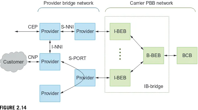
Carrier Ethernet networks consist of Provider Bridge (PB) networks and a Pro-vider Backbone Bridge (PBB) network as shown inFigure 2.14. Provider bridging utilizes an additional VLAN tag (Q-in-Q) to tunnel packets between customers using several types of interfaces. Customer Edge Ports (CEP) connect to customer equip-ment while Customer Network Ports (CNP) connect to customer networks. Provider
Provider I-NNI
S-NNI
S-PORT
Provider bridge network Carrier PBB network
CEP
CNP
I-BEB
I-BEB
B-BEB
IB-bridge
BCB Customer Provider
Provider Provider Provider
FIGURE 2.14