MPLS-Enabled Applications
Emerging Developments and
New Technologies
Ina Minei
Juniper Networks
deployed. Minei and Lucek, however, have taken the subject on to the next level. They explain the new and significant developments in MPLS showing how the technology has come of age and how it will be used to build advanced services in complex, interconnected networks. This book provides an important tutorial on the recent advances in MPLS, and brings together many of the threads from the IETF to provide a comprehensive overview of the next generation of MPLS networking.’
Adrian Farrel, Old Dog Consulting Ltd., IETF CCAMP and PCE working groups co-chair
‘While MPLS is in itself simple, its apparent complexity lies in the proliferation of applications, which shows no signs of ceasing. To make things worse, catching up involves reading a large number of documents written by various authors at various times in various styles. Here at last is a single, all-encompassing resource where the myriad applications sharpen into a comprehensible text that first explains the whys and whats of each application before going on to the technical detail of the hows.’
Kireeti Kompella, Juniper Fellow, Juniper Networks.
‘MPLS-Enabled Applications thoroughly covers the MPLS base technology and applications on MPLS-enabled IP networks. It guides you to a comprehensive understanding of standards, problems, and solutions in networking with MPLS. Before it had been necessary to go through material from many different sources, here we have everything in one place. All the MPLS protocols are covered, as are the applications of these protocols. This should be the textbook for MPLS courses, both for training of experienced networking professionals and for universities.’
Loa Andersson, Acreo AB, IAB-member and IETF MPLS working group co-chair
‘This is the MPLS text that the industry has been waiting for. On one hand, the text presents MPLS technology clearly enough that the reader can absorb its content in a few easy sittings. On the other hand, the text provides a sufficiently in depth treatment that even an MPLS expert can learn from it. The authors offer a clear and complete description of MPLS, its inner workings and its applications, in a manner that could only be achieved by persons who have been significant contributors to the MPLS development effort. Every network operator who has deployed or is considering the deployment of MPLS technology should read this book. It is appro-priate reading for everyone from the CTO to the tier 1 NOC engineer.’
Ron Bonica, Engineer, Juniper Networks, IETF L3 VPN working groupco-chair
Robert Raszuk, Technical Leader, Routing Protocols Deployment and Architecture, Cisco Systems
‘MPLS-Enabled Applications provides an excellent review of the fundamentals and key applications of the MPLS suite of protocols. Its balanced mix of both the technical and business motivations for using these applications make it a must-read for anyone involved in enterprise or service-provider networks.’
Dave Cooper, Sr. Manager IP Engineering, Global Crossing, Ltd.
‘This is a highly recommended book for those wanting to update themselves with the latest MPLS developments, or those just wanting to learn this technology thoroughly. In addition to the impressive technology coverage and depth, the book is also a delightful reading!’
Lei Wang, IP Network Architect, Telenor
‘MPLS-Enabled Applications is an excellent read for network engineers involved in the design of MPLS networks and services. It can serve as an introduction to MPLS networking or as a reference book for the advanced engineer. It discusses practical issues that must be considered in the design of MPLS networks and services, including MPLS-TE, MPLS-IPVPNs and MPLS L2 VPNs. It also discusses current topics that are still evolving in the industry such as inter-AS/area MPLS-TE, point-to-multipoint LSPs and IPVPN multicast, providing a good overview of the issues being addressed and the current industry direction.’
Nabil N. Bitar, Principal member of Technical Staff and lead network architect, Verizon
‘MPLS Enabled Applications presents the current state of the art in the specification, development, and application of MPLS and its related technologies. I believe, the readers will find the book to be a very valuable resource.’
Bijan Jabbari, PhD, Founder of Isocore, and Professor of Electrical Engineering, George Mason University
‘Too few people have the scarce skill for clearly explaining things. Fewer still have a clear understanding of the MPLS protocol and architectures. Minei and Lucek seem to have them both.’
Dr. Eyal Felstaine, senior staff member, Ben Gurion University, Israel
‘This book provides an excellent overview of MPLS mechanisms and applications. It allows understanding what we can do today and what we will be able to do tomorrow with MPLS, as it covers not only stable and deployed technologies such as MPLS Fast Reroute, L3 VPNs, L2 VPN, but also new technologies under development within the IETF, such as IP/LDP Fast Reroute, inter-domain Traffic Engineering and Point-To-Multipoint MPLS. Hence this book will be highly useful for network designers, operators, students as well as anyone interested with the MPLS architecture.’
MPLS-Enabled Applications
Emerging Developments and
New Technologies
Ina Minei
Juniper Networks
Telephone (+44) 1243 779777
Email (for orders and customer service enquiries): [email protected] Visit our Home Page on www.wiley.com
All Rights Reserved. No part of this publication may be reproduced, stored in a retrieval system or transmitted in any form or by any means, electronic, mechanical, photocopying, recording, scanning or otherwise, except under the terms of the Copyright, Designs and Patents Act 1988 or under the terms of a licence issued by the Copyright Licensing Agency Ltd, 90 Tottenham Court Road, London W1T 4LP, UK, without the permission in writing of the Publisher. Requests to the Publisher should be addressed to the Permissions Department, John Wiley & Sons Ltd, The Atrium, Southern Gate, Chichester, West Sussex PO19 8SQ, England, or emailed to [email protected], or faxed to (+44) 1243 770571.
This publication is designed to provide accurate and authoritative information in regard to the subject matter covered. It is sold on the understanding that the Publisher is not engaged in rendering professional services. If professional advice or other expert assistance is required, the services of a competent professional should be sought.
Other Wiley Editorial Offices
John Wiley & Sons Inc., 111 River Street, Hoboken, NJ 07030, USA Jossey-Bass, 989 Market Street, San Francisco, CA 94103-1741, USA Wiley-VCH Verlag GmbH, Boschstr. 12, D-69469 Weinheim, Germany
John Wiley & Sons Australia Ltd, 42 McDougall Street, Milton, Queensland 4064, Australia John Wiley & Sons (Asia) Pte Ltd, 2 Clementi Loop #02-01, Jin Xing Distripark,
Singapore 129809
John Wiley & Sons Canada Ltd, 22 Worcester Road, Etobicoke, Ontario, Canada M9W 1L1
Library of Congress Cataloging in Publication Data
Minei, Ina.
MPLS-enabled applications : emerging developments and new technologies / Ina Minei, Julian Lucek.
p. cm.
Includes bibliographical references. ISBN 0-470-01453-9 (alk. paper)
1. MPLS standard. 2. Extranets (Computer networks) I. Lucek, Julian. II. Title. TK5105.573.M56 2005
621.382′16—dc22
2005022611
British Library Cataloguing in Publication Data
A catalogue record for this book is available from the British Library ISBN 0-470-01453-9
Typeset in 11/13pt Palatino by Integra Software Services Pvt. Ltd, Pondicherry, India Printed and bound in Great Britain by Antony Rowe Ltd, Chippenham, Wiltshire
MPLS-Enabled Applications: Emerging Developments and New Technologies Ina Minei and Julian Lucek © 2005 John Wiley & Sons, Ltd
About the Authors xiii
Foreword xv
Preface xix
Acknowledgements xxiii
Part One 1
1 Foundations 3
1.1 Historical perspective 3
1.2 Current trends 5
1.3 MPLS mechanisms 6
1.3.1 Forwarding plane mechanisms 8
1.3.2 Control plane mechanisms 12
1.4 Conclusion 34
1.5 References 34
1.6 Further reading 36
2 Traffic Engineering with MPLS (MPLS-TE) 37
2.1 Introduction 37
2.2 The business drivers 38
2.3 Application scenarios 39
2.4 Setting up traffic-engineered paths using MPLS-TE 42
2.4.1 LSP priorities and preemption 42
2.4.3 Path calculation – CSPF 45 2.4.4 Path setup – RSVP extensions and admission control 48
2.5 Using the traffic-engineered paths 51
2.6 Deployment considerations 55
2.6.1 Scalability 55
2.6.2 Reservation granularity 57
2.6.3 Routing challenges 58
2.7 Using traffic engineering to achieve resource optimization 59 2.7.1 Autobandwidth – dealing with unknown bandwidth
requirements 60
2.7.2 Sharing links between RSVP and other traffic – dealing
with unknown bandwidth availability 60
2.7.3 Other methods for optimization of transmission resources
in MPLS networks 62
2.8 Offline path computation 63
2.9 Conclusion 66
2.10 References 66
2.11 Further reading 67
3 Protection and Restoration in MPLS Networks 69
3.1 Introduction 69
3.2 The business drivers 70
3.3 Failure detection 71
3.4 End-to-end protection 73
3.5 Local protection using fast reroute 75
3.6 Link protection 78
3.6.1 What happens before the failure 79
3.6.2 What happens after the failure 84
3.7 Node protection 86
3.8 Additional constraints for the computation of the protection path 88
3.8.1 Fate sharing 88
3.8.2 Bandwidth protection 90
3.8.3 Bandwidth protection and DiffServ 93
3.9 Interaction of end-to-end protection and fast reroute 94 3.10 Deployment considerations for local protection
mechanisms 95
3.10.1 Scalability considerations 95
3.10.2 Evaluating a local protection implementation 98
3.10.3 The cost of bandwidth protection 101
3.11 IP and LDP FRR 103
4.3 Application scenarios 113 4.3.1 Limiting the proportion of traffic from a particular
class on a link 113
4.3.2 Maintaining relative proportions of traffic on links 115
4.3.3 Providing guaranteed bandwidth services 116
4.4 The DiffServ-TE solution 116
4.4.1 Class types 116
4.4.2 Path computation 117
4.4.3 Path signaling 120
4.4.4 Bandwidth constraint models 120
4.4.5 Overbooking 126
4.4.6 The DiffServ in DiffServ-TE 128
4.4.7 Protection 129
4.4.8 Tools for keeping traffic within its
reservation limits 130
4.4.9 Deploying the DiffServ-TE solution 132
4.5 Extending the DiffServ-TE solution with
multiclass LSPs 133
4.6 Conclusion 134
4.7 References 134
4.8 Further reading 135
5 Interdomain Traffic Engineering 137
5.1 Introduction 137
5.2 The business drivers 138
5.3 Setting up interdomain TE LSPs 139
5.3.1 Path setup 140
5.3.2 Path computation 145
5.3.3 Reoptimization 156
5.3.4 Protection and fast reroute 157
5.4 Interprovider challenges 160
5.5 Comparison of the LSP setup methods 161
5.6 Conclusion 162
5.7 References 162
5.8 Further reading 164
6 Point-to-Multipoint LSPs 165
6.1 Introduction 165
6.2 The business drivers 166
6.3 P2MP LSP mechanisms 168
6.3.1 Forwarding plane mechanisms 168
6.3.2 Control plane mechanisms 169
6.4 LAN procedures for P2MP LSPs 178
6.5 Coupling traffic into a P2MP LSP 181
6.5.1 Coupling Layer 2 traffic into a P2MP LSP 181
6.5.2 Coupling IP unicast traffic into a P2MP LSP 182
6.6 MPLS fast reroute 185
6.7 Applications of point-to-multipoint LSPs 187
6.7.1 Application of P2MP TE to broadcast TV distribution 187 6.7.2 Application of P2MP LSPs to L3 VPN multicast 190
6.7.3 Application of P2MP LSPs to VPLS 191
6.8 Conclusion 192
6.9 References 192
Part Two 195
7 Foundations of Layer 3 BGP/MPLS Virtual Private Networks 197
7.1 Introduction 197
7.2 The business drivers 198
7.3 The overlay VPN model 199
7.4 The peer VPN model 201
7.5 Building the BGP/MPLS VPN solution 204
7.5.1 VPN routing and forwarding tables (VRFs) 204
7.5.2 Constrained route distribution 206
7.5.3 VPN-IPv4 addresses and the route distinguisher (RD) 207
7.5.4 The route target (RT) 209
7.5.5 The solution so far – what is missing? 215
7.5.6 VPN label 216
7.6 Benefits of the BGP/MPLS VPN solution 221
7.7 References 222
7.8 Further reading 222
8 Advanced Topics in Layer 3 BGP/MPLS Virtual Private Networks 223
8.1 Introduction 223
8.2 Routing between CE and PE 223
8.3 Route reflectors and VPNs 228
8.4 Scalability discussion 233
8.4.1 Potential scaling bottlenecks 233
8.4.2 The cost of growing the VPN network 236
8.5 Convergence times in a VPN network 241
8.5.1 Convergence time for a customer route change 242 8.5.2 Convergence time for a failure in the provider’s network 242
8.6 Security issues 243
8.7 QoS in a VPN scenario 245
8.8 Multicast in a VPN 247
8.8.1 The original multicast solution 248
8.8.2 Improving the existing multicast solution 253
8.9 Conclusion 258
8.10 References 258
8.11 Further reading 259
9 Hierarchical and Inter-AS VPNs 261
9.1 Introduction 261
9.2.1 ISP as a VPN customer 264 9.2.2 VPN service provider as a VPN
customer – hierarchical VPN 269
9.3 Multi-AS backbones 273
9.3.1 Option A: VRF-to-VRF connections at the ASBR 274 9.3.2 Option B: EBGP redistribution of labeled VPN-IPv4 routes 275 9.3.3 Option C: multihop EBGP redistribution of labeled
VPN-IPv4 routes between the source and destination AS, with EBGP redistribution of labeled IPv4 routes from one
AS to the neighboring AS 277
9.4 Interprovider QoS 278
9.5 Conclusion 280
9.6 References 280
9.7 Further reading 280
10 Layer 2 Transport over MPLS 283
10.1 Introduction 283
10.2 The business drivers 283
10.3 Comparison of Layer 2 VPNs and Layer 3 VPNs 286
10.4 Principles of Layer 2 transport over MPLS 287
10.5 Forwarding plane 289
10.5.1 ATM cell 291
10.5.2 ATM AAL5 292
10.5.3 Frame relay 292
10.5.4 Ethernet 293
10.6 Control plane operation 293
10.6.1 LDP signaling scheme 294
10.6.2 BGP-based signaling and autodiscovery scheme 295 10.6.3 Comparison of BGP and LDP approaches to Layer 2
transport over MPLS 300
10.7 Failure notification mechanisms 301
10.8 Layer 2 interworking 302
10.9 Circuit cross connect (CCC) 303
10.10 RSVP signaling for interdomain pseudowires 305
10.11 Other applications of Layer 2 transport 309
10.12 Conclusion 311
10.13 References 312
11 Virtual Private LAN Service 315
11.1 Introduction 315
11.2 The business drivers 315
11.3 VPLS mechanism overview 317
11.4 Forwarding plane mechanisms 321
11.4.1 Forwarding of unicast frames 322
11.4.2 Broadcast and multicast frames 325
11.5 Control plane mechanisms 326
11.5.1 LDP-based signaling 327
11.5.3 Comparison of LDP and BGP for VPLS control plane
implementation 339
11.5.4 Operational considerations 344
11.6 Conclusion 345
11.7 References 346
12 MPLS Management 347
12.1 Introduction 347
12.2 Management – why and what 347
12.3 Detecting and troubleshooting failures 349
12.3.1 Reporting and handling nonsilent failures 349
12.3.2 Detecting silent failures – MPLS OAM 351
12.3.3 Troubleshooting failures 362
12.4 Configuration errors 366
12.4.1 Preventing configuration errors 366
12.4.2 Detecting and reporting misconfigurations 369
12.5 Visibility 374
12.6 Conclusion 375
12.7 References 375
12.8 Further reading 376
13 Conclusions 379
13.1 Introduction 379
13.2 Network convergence 380
13.3 Interaction with client edge equipment 385
13.4 Interprovider capability 386
13.5 MPLS in the access network 387
13.6 MPLS in the enterprise 388
13.7 Final remarks 389
13.8 References 390
Acronyms 391
MPLS-Enabled Applications: Emerging Developments and New Technologies Ina Minei and Julian Lucek © 2005 John Wiley & Sons, Ltd
Ina Minei has been a network protocols engineer at Juniper Networks for the past five years working on next-generation network technologies for core routers, where she focuses on MPLS protocols and applications. She previously worked at Cisco for two years in various software development projects for routers and switches. Ms Minei is an active participant in industry fora and conferences and has co-filed several patents in the area of IP and MPLS. She holds a Master’s degree in computer science from the Technion, Israel.
MPLS-Enabled Applications: Emerging Developments and New Technologies Ina Minei and Julian Lucek © 2005 John Wiley & Sons, Ltd
Yakov Rekhter, Juniper Fellow, Juniper Networks,
June 2005
Multi-Protocol Label Switching (MPLS) began in the mid-1990s with just two modest design objectives. The first was a better inte-gration of ATM with IP by providing a single IP-based control plane that could span both ATM switches and IP routers. The second objective was to augment the IP control plane with some additional functionality, namely traffic engineering using constraint-based routing that was already present in the ATM control plane.
Not long after it started, MPLS usage was extended to applications such as Circuit Cross Connect (CCC), ATM and Frame Relay service over an IP/MPLS infrastructure (draft-martini), and BGP/MPLS VPNs (2547 VPNs). The original constraint-based routing function-ality evolved beyond traffic engineering to applications such as fast reroute and Differentiated Services Traffic Engineering (DiffServ-TE). The idea of a single control plane for both ATM switches and IP routers evolved into Generalized Multi-Protocol Label Switching (GMPLS), which provides a single control plane that could span not only routers and ATM switches but SONET/SDH and optical cross connects as well.
developments deserving of mention here, the first being the work on point-to-multipoint Label Switched Paths (P2MP LSPs), which is expected to be used for applications such as video distribution, IP multicast with BGP/MPLS VPNs and IP multicast with VPLS. The second development is the work on extending constraint-based routing, including applications such as traffic engineering, fast reroute and Differentiated Services Traffic Engineering to multiple OSPF/IS-IS areas and even multiple autonomous systems.
It is important to keep in mind that in all of the applications mentioned above MPLS is just one of the components of such applica-tions, albeit a critical one. If we look back at the time when MPLS was created, and compare its design objectives with what MPLS is used for today, we notice several things. First of all, most of the applications of MPLS that we have today were not conceived of during the original design of MPLS. Furthermore, while the original design goal of a better integration of ATM and IP routers is still with us, the way MPLS today supports this is completely different from the way it was originally conceived. Instead of having a single control plane that could span both ATM switches and routers, ‘better integration’ today has a dual meaning of being able to offer the ATM service over an IP/MPLS infrastructure that has no ATM switches at all, as well as the ability to interconnect ATM switches over such an infrastructure. While originally MPLS was conceived as a technology solely for the Service Providers, we see today how MPLS is gradually penetrating the enterprise environment. Additionally, over time the whole MPLS concept evolved from Multi-Protocol Label Switching to Multi-Purpose Label Switching.
A new technology quite often generates opposition, and MPLS was by no means an exception. You may all remember how MPLS was branded by its opponents in negative terms as ‘bad’, ‘evil’, ‘a social disease’ or ‘a nightmare of unprecedented proportions’. To put this in a proper perspective, we need to keep in mind that technologies exist not for their own sake but for the purpose of solving business problems. Therefore, talking about ‘good’ technologies versus ‘bad/evil’ technologies has little practical relevance; yet what is of great relevance is how well a particular technology meets business needs.
MPLS-Enabled Applications: Emerging Developments and New Technologies Ina Minei and Julian Lucek © 2005 John Wiley & Sons, Ltd
Our aim in writing this book was to describe the latest developments in MPLS. The field is moving so fast that some new applications of MPLS have already been deployed in production networks, yet are not described anywhere in book form. In many cases, the only available resources are the IETF drafts which list the extensions that vendors must implement in order to produce interoperable implementations. These documents often assume familiarity with the problem at hand and omit the details on why a particular solution has been chosen or what are the pros and cons of using it. This book attempts to fill this gap and provide the reader with an under-standing of both the problem and why the solution looks the way it does.
Therefore, when we describe the protocol mechanisms underpin-ning an MPLS application, the emphasis is on giving an overview of the protocol machinery without delving into the bits and bytes of each protocol message. This allows us to convey the concepts without making it difficult to see the wood for the trees. Also, some of the mechanisms that we write about are currently being defined, so some of the details of the protocol messages may change, but the concepts are less likely to. References at the end of each chapter point to the documents describing the message formats and processing rules.
understanding any particular topic. Many of the topics discussed are still under discussion and debate in the IETF, and naturally some-times our personal views on one topic or another may be stated more strongly than the opposing view.
WHO SHOULD READ THIS BOOK?
The intended audience of this book includes employees of service providers and network equipment vendors, customers of service providers who are interested in the mechanisms underpinning the services that they buy, network professionals who want to keep up to date with the latest advances in MPLS and students of network technology. We assume that the reader has some degree of familiarity with network technology and routing protocols, in particular BGP and the link-state IGPs, but these are not a requirement to benefit from the book. Although the main aim of the book is to cover the cutting-edge developments of MPLS, the Foundation chapter allows the reader unfamiliar with MPLS to get up to speed in order to benefit from the remainder of the book. Even when discussing basic topics such as TE or fast reroute, an attempt is made to look at the more interesting and advanced aspects of the technology.
HOW THIS BOOK IS ORGANIZED
The book is divided into two parts, each containing several chapters. Part One describes the MPLS infrastructure tools used as the foundation to build services and Part Two of the book covers the MPLS-based services themselves.
The structure of Part One
Chapter 1, the Foundations chapter, reviews the control plane and forwarding plane mechanisms associated with MPLS. In that chapter, we give an overview of the LDP and RSVP signaling protocols and compare the two.
at the impact of TE on network scalability, as well as at solutions for TE in LDP networks.
Chapter 3 explores the topic of Protection and Restoration in MPLS networks, essential to allowing MPLS networks to carry mission-critical traffic. We cover link and node protection, their respective scaling properties, the cost of bandwidth protection, as well as more advanced topics such as fate sharing and the new developments for providing fast restoration in IP and LDP networks. Chapter 4 presents Differentiated Services (DiffServ) Aware Traffic Engineering, which allows traffic engineering to be applied with per-class granularity, bringing QoS to the network.
Chapter 5 introduces Interdomain Traffic Engineering. This is likely to be of increasing importance in the future as MPLS-based services extend across multiple IGP areas and AS boundaries. Both the signaling and computation aspects are discussed, and path-computation elements are also reviewed.
Chapter 6 is devoted to Point-to-Multipoint MPLS functionality, both RSVP and LDP. This is currently of great interest as it allows MPLS to be used in broadcast TV applications and because it is an essential part of the new L3VPN multicast solutions that are currently under discussion within the IETF.
The structure of Part Two
Chapters 7, 8 and 9 are devoted to Layer 3 VPNs, which is to date the most widespread application of MPLS. Chapter 7 provides a tutorial on L3VPN and explains the basic concepts, while the next chapters discuss more advanced topics such as route target filtering, scalability analysis and hierarchical VPNs.
Chapter 10 describes the rapidly growing area of Layer 2 transport over MPLS, including pseudowires and Layer 2 VPNs. These allow service providers to migrate ATM and Frame Relay services to an IP/MPLS network and to offer Ethernet-based alternatives to those services.
Chapter 11 describes the Virtual Private LAN Service (VPLS). This allows a service provider to offer a very simple-to-use service to enter-prise customers, in which the customer’s sites appear to be attached to the same LAN.
networks could fill an entire book by itself and a single chapter does not do it justice. However, we attempt to show some of the challenges (such as ICMP tunneling) and some of the new tools, such as LSPing. The final chapter takes a look at the achievements of MPLS to date and how MPLS may in future extend beyond the service provider core to access networks and to enterprise networks.
REFERENCES
At the end of each chapter, there is a list of references. In the body of the text, these references appear in brackets, like this [REF1]. Many of the references are IETF documents. As these documents progress in the IETF process, their revision number and document name may change. Therefore, when looking up a reference online, search by the author and title rather than by the document name.
In some chapters, we have included a section with further reading. These are documents that the authors thought would be useful for those wanting to broaden their knowledge on a particular topic.
MPLS-Enabled Applications: Emerging Developments and New Technologies Ina Minei and Julian Lucek © 2005 John Wiley & Sons, Ltd
This book would not have existed if it were not for the following three people: Yakov Rekhter, Aviva Garrett and Patrick Ames, and to them we extend our most heartfelt thanks.
Yakov Rekhter encouraged us to pursue this project and provided valuable insight, starting with the book proposal and ending with a detailed technical review of numerous chapters. Most importantly, his faith in our ability to do this work was one of the main factors that determined us to go ahead with this project.
Aviva Garrett was the first person to hear about this idea, encouraged it and arranged all the required support within Juniper Networks. In addition to this, Aviva provided an editorial review of the entire book. Patrick Ames guided us through the intricate process of bringing a book from proposal to the printing press and provided moral support and appropriate scolding as necessary. We would not have been able to pull this off without him. Patrick also did all the hard work of preparing the manuscript (and in particular the art manuscript) for editing.
This book benefited from the contribution of many people. We would like to thank our following colleagues:
Arthi Ayyangar, for her insight on all topics RSVP and TE-related, for many technical discussions throughout our years of working together and for the careful review of numerous chapters.
Steven Lin, for reading and commenting on the entire manuscript, on a very tight schedule.
Der-Hwa Gan, for his mentoring role on TE, RSVP and MPLS, and for his very thorough technical review and comments.
Chaitanya Kodeboyina (CK), for very detailed reviews and discus-sions on several chapters.
Josef Buchsteiner, for always bringing up tough customer problems and for the timely reviews of selected chapters.
Serpil Bayraktar, for never leaving open ends and for very careful reading of the VPN and interdomain TE chapters.
Amir Tabdili, for always asking the hard questions and for reviewing selected chapters.
Quaizar Vohra, for his insight into Layer 2 circuits and the IGP, and for his technical review of these topics.
Margarida Correia, for always questioning proposed solutions to customer problems, and for technical review of selected chapters.
Hector Avalos, for valuable technical discussions and technical review of selected chapters.
Nischal Sheth, for being a mentor on LDP and for numerous discussions on all topics MPLS-related.
Kireeti Kompella, for many technical discussions and for his insight into all aspects of the MPLS technology.
As always, any errors and omissions are the responsibility of the authors.
We would also like to acknowledge the support and assistance of Juniper Networks and in particular our managers Andy Heffernan, Nischal Sheth and Hector Avalos for encouraging us to work on this project and providing the necessary resources.
Last but not least we would like to thank the wonderful team at
Wiley: Joanna Tootill, Birgit Gruber, Richard Davies, Julie Ward
and Pat Bateson for their support and guidance.
Finally, the authors would like to express their personal thanks to family and friends:
having infinite patience throughout the entire project and for the many sacrificed weekends. I would not have been able to do this without his support. Second, I would like to thank my father for the long hours he spent with me in my high school years, teaching me English and writing.
MPLS-Enabled Applications: Emerging Developments and New Technologies Ina Minei and Julian Lucek © 2005 John Wiley & Sons, Ltd
1
Foundations
1.1
HISTORICAL PERSPECTIVE
In only a few years, Multi-Protocol Label Switching (MPLS) has evolved from an exotic technology to a mainstream tool used by service providers to create revenue-generating services. There is rapid deployment of MPLS-enabled services and active develop-ment of new mechanisms and applications for MPLS in the standards bodies. This book aims to describe the fundamental mechanisms used by MPLS and the main service types that MPLS enables, such as Virtual Private Networks (VPNs). We include descriptions of new applications of MPLS that are currently under development.
MPLS. It is interesting to examine these to see which items are still relevant today:
1. Scalability of network layer routing. Using labels as a means to aggregate forwarding information, while working in the presence of routing hierarchies.
Layer 3 VPNs have proved to be a good example of aggregation of forwarding information. As described in Chapter 7 of this book, edge routers need to contain routing information pertaining to each VPN that they service, but the core routers do not. Thus, assuming that any edge router services only a subset of the VPNs pertaining to the network, no router in the network needs to hold the entire set of routes present in the network.
2. Greater flexibility in delivering routing services. Using labels to identify particular traffic which are to receive special services, e.g. QoS. Using labels to provide forwarding along an explicit path different from the one constructed by destination-based forwarding.
MPLS has the ability to identify particular traffic flows which must receive special services such as Quality-of-Service (QoS). It also has traffic engineering properties that allow it to provide forwarding along a particular explicit path. These two properties are combined in DiffServ Aware Traffic Engineering, which is described in more detail in Chapter 4 of this book.
3. Increased performance. Using the label-swapping paradigm to optimize network performance.
Because modern routers perform packet forwarding in hardware, the forwarding rates for IP and MPLS packets are similar. However, ‘optimizing network performance’ implies a wider context than simply the performance of individual nodes. Certainly MPLS has helped in this wider context, e.g. through the use of traffic engineering to avoid congestion and the use of fast reroute to reduce the interruption to traffic when a link in the network fails.
c) by employing common addressing, routing, and management procedures.
When this item in the problem statement was written, many networks had a core of asynchronous transfer mode (ATM) switches surrounded by routers. The routers were typically fully meshed with ATM connections. This overlay model was proving difficult to scale because the number of routing adjacencies required grew as the square of the number of routers involved; hence there was a requirement to make the ATM switches act as peers to the routers. It is interesting to note that the situation has now been turned inside out: now many networks have an MPLS-based core, and service providers are migrating ATM services to this core network by interconnecting ATM switches with Layer 2 connections over the MPLS core! This has the problem that the number of adjacencies between ATM switches grows as the square of the number of ATM switches involved. Hence, currently there is work on making ATM switches behave as peers to routers [MPLS ALLI]. This is to avoid having a full mesh of adjacencies between ATM switches rather than to avoid having a full mesh of adjacencies between routers, as stated in the problem statement. The concept expressed in the problem statement of using MPLS as a control plane for multiple technologies has manifested itself in Generalized MPLS (GMPLS). In GMPLS, a common control plane covers a wide range of network devices, such as routers, ATM switches, SONET/SDH equipment and optical cross-connects [RFC3945].
In summary, much of the original problem statement is still relevant today. Many of the mechanisms of MPLS described in Part 1 of this book were developed to address the items listed above, to the benefit of the MPLS applications discussed in Part 2 of this book.
1.2
CURRENT TRENDS
Finally, Virtual Private LAN Service (VPLS) offerings, in which the service provider gives the impression to the customer that their sites are attached to the same Local Area Network (LAN), are also becoming available.
Many service providers are investigating the possibility of using an MPLS-based network to provide a common platform for a wide range of services that are currently typically delivered over multiple distinct networks. Such a multiservice network might carry Public Switched Telephone Network (PSTN) traffic, public Internet and private IP data services, Layer 2 ATM and Frame Relay services, Broadcast TV and TDM traffic. This offers capital and operational cost savings to the network operators by allowing them to operate a single network rather than a separate network for each service type. A key aim of this book is to show how MPLS can provide the necessary mechanisms for this network convergence, e.g. through the use of DiffServ Aware Traffic Engineering (TE), which allows the MPLS network to provide connection-orientated characteristics to particular traffic flows.
1.3
MPLS MECHANISMS
This section gives an overview of the mechanisms underpinning MPLS. Readers who are familiar with these may wish to skip this section.
A fundamental property of an MPLS network is that it can be used to tunnel multiple traffic types through the core of the network. Tunneling is a powerful tool because only the routers at the ingress and the egress of the tunnel need to understand the ‘context’ of the underlying traffic carried over the tunnel (e.g. the protocol that the traffic belongs to and the reachability information required to route and forward it in its native form). This detail is hidden from routers in the core of the network. As a consequence, core devices only need to carry sufficient state to enable them to switch MPLS-encapsulated packets without regard to their underlying content. Besides these aggregation properties, which apply to tunnels in general, MPLS tunnels have the following particular properties:
1. Traffic can be explicitly routed, depending on which signaling protocol is used.
3. There is protection against data spoofing, as the only place where data can be injected into an MPLS tunnel is at the head end of that tunnel. In contrast, data can be injected into an IP tunnel from any source that has connectivity to the network that carries the tunnel.
4. The encapsulation overhead is relatively low (4 bytes per MPLS header).
An MPLS network consists of edge devices known as Label Edge Routers (LERs) or Provider Edge (PE) routers and core routers known as Label Switching Routers (LSRs) or Provider (P) routers. A mesh of unidirectional tunnels, known as Label Switched Paths (LSPs) is built between the LERs in order that a packet entering the network at the ingress LER can be transported to the appropriate egress LER. When packets enter a network, the ingress router determines which Forwarding Equivalence Class (FEC) the packets belong to. Packets that are to be forwarded to the same egress point in the network along the same path and with the same forwarding treatment along that path are said to belong to the same FEC. Packets belonging to the same FEC are forwarded with the same MPLS label. In a simple case, packets whose destination addresses correspond to the same Border Gateway Protocol (BGP) next-hop are regarded by the ingress router as belonging to the same FEC. In other cases, there may be a more granular assignment of packets to FECs. For example, in DiffServ Aware TE, each egress point in the network may have multiple FECs, each belonging to a different traffic class.
The following sections describe the fundamental forwarding plane and control plane mechanisms underpinning MPLS.
1.3.1
Forwarding plane mechanisms
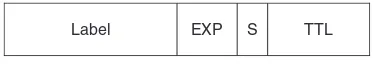
Data carried over an MPLS-capable network has one or more MPLS headers applied in order to transport it across the network. The MPLS header structure is shown in Figure 1.1. It contains the following fields:
1. A 20-bit label value. MPLS packets are forwarded on the basis of this field. This value is used as an index into the MPLS forwarding table.
2. EXP field (3 bits). These bits are known as the experimental bits. In practice, they are used to convey the Class of Service to be applied to the packet. For example, LSRs and LERs can use these bits to determine the queue into which the packet should be placed. Note that in some cases, as described later in this chapter, the MPLS label value also determines the queuing behaviour applied to the packet.
3. Bottom of stack bit (S-bit). As described later in this chapter, MPLS headers can be stacked. The S-bit is set on the header of the MPLS packet at the bottom of the stack.
4. Time-to-live (TTL) field. This is used to avoid forwarding loops and can also be used for path-tracing. The value is decremented at each hop and the packet is discarded should the value reach zero.
Packets arriving into the network have one or more MPLS headers applied by the ingress LER. The ingress LER identifies the egress LER to which the packet must be sent and the corresponding LSP. The label value used corresponds to the LSP on to which the packet is placed. The next router performs a lookup of that label and determines the output label that must be used for the next leg of the LSP. The lookup operation on a P router involves reading
TTL S
EXP Label
the incoming label; this yields a new label value to use and the output interface(s) on which the packet should be forwarded. In this way, through this label-swapping paradigm, the packet is conveyed along the LSP from the ingress to the egress LER.
In some simple cases, the use of a single MPLS label is sufficient, e.g. when transporting public IP traffic across a network. In this case, once the packet arrives at the egress LER, the LER performs a normal IP lookup in order to determine which egress link to use. Usually a scheme called Penultimate Hop Popping (PHP) is used. In this scheme, the LSR before the egress LER (i.e. the penultimate router along the LSP) pops the MPLS label and forwards it to the egress LER as an IP packet. This simplifies the processing required at the egress node, as otherwise it would be necessary to pop the label and perform an IP lookup at the egress node.
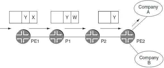
In other cases, a single MPLS header is insufficient. This is because the LERs in a particular network may be involved in multiple services – Layer 3 VPN, Layer 2 VPN, VPLS – rather than just the public IP. In this case, the egress LER needs to know which service and which instance of that service (i.e. which customer) the packet belongs to. This is achieved by having an additional MPLS header, which is applied by the ingress LER, corresponding to the service and service instance that the packet must be directed to by the egress LER once the packet has crossed the network. This is illustrated in Figure 1.2.
Let us see how an MPLS packet with two headers is transported between the ingress and egress LERs. The inner header with label Y denotes the service and service instance, and the outer header, often called the ‘transport’ header, is the one required to transport the packet from the ingress LER, PE1, to the correct egress LER, PE2. For example, a particular LER may be running several Layer 3 VPN, VPLS and Layer 2 VPN instances. Label Y tells the egress LER that the packet in question corresponds to the Layer 3 VPN service being provided to Company A, rather than any of the other
TTL Outer or top header Inner or bottom header
Layer 3 VPN instances or the VPLS or Layer 2 VPN instances. The ability to stack headers in this way gives MPLS key multiplexing and hierarchical properties, allowing a single LSP between a particular ingress and egress point to carry all traffic between those points. As Figure 1.3 shows, the packet leaves the ingress LER, PE1, with an inner label value of Y and an outer label value of X. Routers P1 and P2 perform a lookup based on the outer transport label and do not need to read or take any action based on the inner label. P1 swaps outer label X with outer label W. If PHP is in use, which is typically the case, router P2 pops the outer header, and sends the remainder of the packet to PE2. Thus, when the packet arrives at PE2, the outermost (and only) label is the original inner label, Y, which PE2 uses to identify the packet as belonging to the Layer 3 VPN instance pertaining to Company A.
How does the ingress LER know the label value(s) to use? The transport label is learnt through either the RSVP or LDP signaling protocols, which are described in more detail later on in this chapter. The inner label in the case of most services is learnt via BGP (e.g. Layer 3 VPNs, BGP-signaled Layer 2 VPNs). However, there are also cases where LDP is used, e.g. LDP-signaled Layer 2 transport circuits.
1.3.1.1 MPLS support of DiffServ
DiffServ was developed as a solution to provide Quality-of-Service (QoS). It does so by dividing traffic into a small number of classes and allocating network resources on a per-class basis. To avoid the need for a signaling protocol, the class is marked directly within
P1 P2
PE1 PE2
Y X Y Y
Company A
Company B W
the packet header. The DiffServ solution was targeted at IP networks so the marking is in the 6-bit DiffServ Code Point (DSCP) field in the IP header. The DSCP determines the QoS behavior of a packet at a particular node in the network. This is called the per-hop behavior (PHB) and is expressed in terms of the scheduling and drop preference that a packet experiences. From an implementation point of view, the PHB translates to the packet queue used for forwarding, the drop probability in case the queue exceeds a certain limit, the resources (buffers and bandwidth) allocated to each queue and the frequency at which a queue is serviced.
The first challenge with supporting DiffServ in an MPLS network is that LSRs make their forwarding decisions based on the MPLS header alone, so the per-hop behavior (PHB) needs to be inferred from it. The IETF solved this problem by assigning the three experimental (EXP) bits in the MPLS header to carry DiffServ information in MPLS. This solution solves the initial problem of conveying the desired PHB in the MPLS header, while introducing a new one: how does one map DSCP values expressed in a 6-bit field that can encode up to 64 values into a 3-bit EXP field that can carry at most eight distinct values? There are two solutions to this problem, discussed separately below.
The first solution applies to networks that support less than eight PHBs. Here, the mapping is straightforward: a particular DSCP is equivalent to a particular EXP combination and maps to a particular PHB (scheduling and drop priority). During forwarding, the label determines where to forward the packet and the EXP bits determine the PHB. The EXP bits are not a property that is signaled when the label-switched path (LSP) is established; the mapping of EXP to PHB is configured on each node in the network. The EXP bits can be set according to the DSCP bits of the IP packets carried in the LSP, or they can be set by the network operator. LSPs for which the PHB is inferred from the EXP bits are called E-LSPs (where E stands for ‘EXP-inferred’). E-LSPs can carry packets with up to eight distinct per-hop behaviors in a single LSP.
Thus, the PHB is determined from both the label and the EXP bits. Because the label is implicitly tied to a per-hop behavior, this information needs to be conveyed when the LSP is signaled. LSPs that use the label to convey information about the desired PHB are called L-LSPs (where L stands for ‘label-inferred’). L-LSPs can carry packets from a single PHB or from several PHBs that have the same scheduling regimen but differ in their drop priorities (e.g. the set of classes AFxy where x is constant are treated the same from the scheduling point of view but differ in their drop
priority according to the value of y). Table 1.1 summarizes the
differences between E-LSPs and L-LSPs.
1.3.2
Control plane mechanisms
So far we have seen how MPLS uses labels for forwarding, but how are the bindings between labels and FECs distributed throughout the network? Since manual configuration is not an option, there clearly is a need for a protocol to disseminate this information. From a practical point of view, there are two options: (a) invent a new protocol for distributing label bindings or (b) extend
Table 1.1 Comparison of E-LSPs and L-LSPs
E-LSP L-LSP
PHB is determined by the EXP bits PHB is determined by the label or by the label and EXP bits together
Can carry traffic with up to 8 distinct PHBs in a single LSP
A single PHB per LSP or several PHBs with the same scheduling regimen and different drop priorities
Conservative label usage and state maintenance, because the label is used only for conveying path information
Uses more labels and keeps more state, because the label conveys information about both the path and the scheduling behavior
No signaling is required to convey the PHB information
The PHB information needs to be signalled when the LSP is established Up to 8 PHBs can be supported in the
network when only E-LSPs are used. E-LSPs can be used in conjunction with L-LSPs when more PHBs are required
an existing protocol to carry labels in addition to routing information. The question of whether to invent a new protocol or extend an existing one is a popular one in the MPLS world, and we will discuss it in detail in later chapters. At this point, suffice it to say that when the question arises, the result is usually that both approaches are followed.
Regarding the distribution of label bindings, the engineering community invented a new protocol (LDP, or Label Distribution Protocol) and extended two existing protocols (RSVP, or Resource Reservation Protocol, and BGP, or Border Gateway Protocol). The packet formats and basic operation of these protocols are explained in detail in many introductory texts [Doyle Kolon, Osborne Simha]. Instead of repeating this information here, let us instead examine the properties of the different protocols, and see the benefits and limitations of each of them.
1.3.2.1 LDP
LDP [RFC3036] is the result of the MPLS Working Group [MPLS WG] in the IETF. Unlike RSVP or BGP, which existed well before MPLS and were extended to do label distribution, LDP was specifically designed to distribute labels in the network. Since the goal of LDP is label distribution, LDP does not attempt to perform any routing functions and relies on an Interior Gateway Protocol (IGP) for all routing-related decisions. The original LDP specification was defined for setting up LSPs for FECs representing an IPv4 or IPv6 address. This is the functionality described in this section. The extensions of LDP used for pseudo-wire and VPLS signaling will be discussed in the appropriate chapters.
LDP operation is driven by message exchanges between peers. Potential peers, also known as neighbors, are automatically discovered via hello messages multicast to a well-known UDP port. The protocol also allows for discovery of remote peers using targeted hello messages. Once a potential peer is discovered, a TCP connection is established to it and an LDP session is set up. At session initialization time, the peers exchange information regarding the features and mode of operation they support. After session setup, the peers exchange information regarding the binding between labels and FECs over the TCP connection. The use of TCP ensures reliable delivery of the information and allows for incre-mental updates, rather than periodic refreshes. LDP uses the regular receipt of protocol messages to monitor the health of the session. In the absence of any new information that needs to be communicated between the peers, keepalive messages are sent.
The association between an FEC and a label is advertised via label messages: label mapping messages for advertising new labels, label withdraw messages for withdrawing previously advertised labels, etc. The fundamental LDP rule states that LSR A that receives a mapping for label L for FEC F from its LDP peer LSR B will use label L for forwarding if and only if B is on the IGP shortest path for destination F from A’s point of view. This means that LSPs set up via LDP always follow the IGP shortest path and that LDP uses the IGP to avoid loops.
Relationship between LDP and the IGP
The fact that LDP relies on the IGP for the routing function has several implications:
1. LDP-established LSPs always follow the IGP shortest path. The LSP path shifts in the network when the IGP path changes, rather than being nailed down to a pre-defined path.
2. The scope of LDP-established LSPs is limited to the scope of the IGP. Thus, LDP LSPs cannot traverse autonomous system (AS) boundaries. The need for Inter-AS LSPs, as well as the solution proposed by the IETF for establishing them, is explained in the Interdomain Traffic Engineering chapter of this book (Chapter 5).
of life for the IGPs during reconvergence. The same properties are inherited by LDP, by virtue of it relying on the IGP for routing decisions. We will discuss how such loops are created and what their impact is in the Protection and Restoration chapter of this book (Chapter 3).
4. The IGP convergence time poses a lower bound on the LDP convergence time. Assuming that the IGP implements smart fast-convergence mechanisms the traffic loss is in the range of 1–2 seconds, orders of magnitude larger than RSVP’s fast-reroute time. The IETF is currently working on adding fast-reroute capa-bilities to LDP. This is discussed in more detail in the Protection and Restoration chapter of this book (Chapter 3).
5. Loss of synchronization between the IGP and LDP can result in traffic loss. As always, for situations where two protocols must operate in tandem, there is a potential for race conditions.
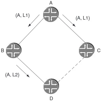
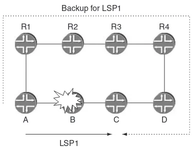
Let us take a closer look at a race condition caused by the loss of synchronization between LDP and the IGP. In the diamond-shaped topology in Figure 1.4, LSR A is advertising a binding for its loopback FEC A. To start with, all links have the same metric, and the link C–D does not exist in the topology. From D’s point of view, the LSP for FEC A follows the path D–B–A. At a later time the link C–D is added to the topology with a metric that is better than the metric of link B–D, causing the IGP shortest path from D’s
A
C B
D (A, L1)
(A, L2)
(A, L1)
point of view to be D–C–A. Assume that the IGP reacts faster than LDP. As soon as D finds out about the routing change, it stops using the binding it received from B, thus breaking the LSP. The LSP stays down until a binding for FEC A is received on the LDP session C–D. This may take a while, depending on how fast the session establishment takes place. The situation described here is particularly unattractive, since an alternate path exists in the topology and could have been used until the LDP session comes up on the link C–D.
The above example shows a loss of synchronization caused by the fact that the LDP session on the new link comes up after the IGP session. This is not the only way in which loss of synchroni-zation can occur: forgetting to enable LDP on the new interface, mis-configuring the LDP session authentication, setting up firewall filters that block LDP traffic, or any other event that would cause the IGP to take into account a link but would cause LDP not to use the link, has the same effect.
One solution to this problem is to tie (through configuration) the IGP metric for a particular link to the existence of an LDP session on the link [LDP-IGP-SYNC]. When the LDP session is down, the IGP metric advertised for the link is very high. Therefore, if an alternate path is available, the LDP labels on that path can be used. This is discussed in more detail in the MPLS Management chapter of this book (Chapter 12).
So far we have seen the implications of having LDP rely on the IGP for the routing function. Next, let us take a look at the choice of label distribution and retention modes made by common LDP implementations.
Label retention and label distribution modes
coupled with the fact that label space is not a concern in modern routers means that most implementations today use liberal retention.
Label distribution mode – who assigns the labels? The key function of LDP is to distribute bindings between labels and FECs. The goal is to build a forwarding table containing a mapping between an incoming label and an outgoing label. Traffic arriving at the LSR labeled with the incoming label is forwarded labeled with the outgoing label. When building the forwarding table, the question is whether to use the locally picked label as the incoming or the outgoing label. The MPLS architecture [RFC3031] uses down-stream label assignment, which means that the router expects to receive the traffic with the label that it picked locally. For example, if LSR A receives label L1 for FEC F and advertises label L2 for it, then it expects traffic destined for FEC F to come labeled with label L2. When forwarding traffic for FEC F, LSR A labels the traffic with label L1. The traffic flows in the opposite direction from the distribution of labels. The method is called downstream because the label that is assigned to the traffic at point P in the network was actually picked by a router who is one hop further down in the direction of the traffic flow (downstream) from P.
The next question is: should labels be advertised only to those asking for them (on-demand label distribution) or to everyone (unsolicited label distribution)? We have already seen that on-demand label distribution has the undesirable property that traffic is blackholed until the request for the label is satisfied. For this reason, most implementations use the unsolicited label distribution mode. Since LDP uses downstream label allocation, the label distribution mode is usually referred to as downstream unsolicited.
Control over the LSP setup
The sole purpose of distributing bindings between labels and FECs is to establish label-switched paths in the network. So far we have discussed a lot of interesting properties of LDP but have not yet answered two key questions: (a) which FEC to advertise a binding for and (b) when to advertise this binding.
The choice of FECs is derived from the LSPs that must be set up in the network. It is independent of the LDP protocol and therefore the LDP specification is silent on this topic. All vendors allow control over the choice of FECs through configuration, but the behavior in the absence of a user-defined configuration is different for different vendors. Some advertise a binding for every prefix in their routing table, while others only advertise a binding for the FEC corresponding to the LSR’s loopback address. The outcome in terms of the numbers of LSPs that are set up and of the destinations reachable via these LSPs is quite different. There is no right or wrong decision here, as different implementations may have different constraints. However, from a network operations point of view, it is a bad idea to allow LDP to advertise bindings for FECs that will not be used for forwarding. The extra binding and LSP information uses up resources in the network and makes troubleshooting extremely difficult.
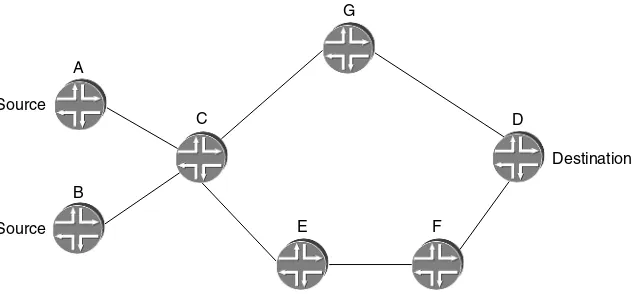
The choice of FEC determines which LSPs are set up. The decision when to advertise the label binding determines who has control over the LSP setup. The LDP specification allows two modes of operation: ordered control and independent control. Since not all vendors implement the same mode, let us take a closer look at the two options and their properties, by reference to Figure 1.5. For the purposes of this discussion, assume that link if5 does not exist. This link will be used for a later discussion in this section.
ingress. Each LSR consults the IGP for two decisions: (a) whether to advertise a mapping for an FEC and (b) whether to use a label for forwarding.
Independent control. With independent control, each LSR assigns a label for FEC PE1 and advertises this binding independently of the peers. Each LSR uses the locally assigned label as its incoming label in the forwarding table. The outgoing label in the forwarding table is filled in when the LSR receives a label for PE1 from a peer lying directly on the IGP shortest path for prefix PE1. The LSRs use the IGP for just one decision: whether to use a label for forwarding or not. The success of the LSP establishment depends on all LSR advertising labels for the same set of FECs. If LSR A were configured not to advertise a label for FEC PE1, the LSP to PE1 would never be established.
At this point, it is probably already clear that the default behavior regarding the choice of FECs that are advertised, which we discussed earlier in this section, is not an arbitrary one. With ordered control, the router who is the egress of the LSP decides which FECs to initiate LSPs for. Thus, a reasonable default behavior for an implementation performing ordered control is to advertise a mapping for the loopback address of the egress. With independent control, all routers in the network must advertise the same set of
PE2 PE1
A B
C
if4 if2 if1
(PE1,L3) (PE1,L2) (PE1,L1) (PE1,L4)
PE1-push L4
if3
Swap (L2, L1) Swap (L3, L2)
Swap (L4, L3)
if5
FECs. Thus, the reasonable thing for an implementation performing independent control is to advertise a mapping for all prefixes in the routing table. Another point to note is that when changing the default behavior via configuration, with ordered control the change is applied to one router only (the egress), while with independent control the change must be uniformly applied throughout the network. The requirement for a uniformly applied change is due to the independent operation of the routers in the network: unless they agree on the same set of FECs to advertise, LSPs will not establish end-to-end throughout the network, causing traffic blackholing. This situation is made worse by the fact that the protocol has no built-in mechanisms for detecting such misconfigurations.
The different behavior with regards to the propagation of labels has important implications regarding the setup of LSPs. With ordered control, the bindings must propagate from the egress to the ingress before the LSP is established and traffic can be forwarded on to it. If an application (such as a Layer 3 VPN) relies on the existence of the LSP, then it cannot forward traffic. This behavior is not limited to the initial setup of LSPs. The same dynamics apply when routing changes. With ordered control labels must propagate to the routers in the new IGP path, while with independent control the labels are already available on these routers. This, however, is not as bad as it looks: when routing changes, the IGP messages themselves must propagate and new routes computed, so the propagation of LDP labels is no worse than the propagation of IGP messages.
A more interesting scenario is a failure case where LDP cannot follow the IGP. Let us go back to the example in Figure 1.5. Assume that the interface if5 does not yet exist in the network. The LSP for FEC PE1 (the loopback of router PE1) establishes along the routers PE2–C–B–A–PE1. At this point, the operator decides to add the interface if5 and includes it in the IGP, but forgets to enable LDP on it. As a result, the IGP best path from router C for FEC PE1 is C–A–PE1.
changed and that the outgoing label it installed in the forwarding table for FEC PE1 is no longer valid and removes the forwarding state for FEC PE1. PE2 does not change its forwarding state, since from its point of view the best path to PE1 is still through C. The net effect is that the LSP for PE1 is broken at point C, but PE2 is unaware of the failure. It will continue to send labeled traffic on this LSP and the traffic will be dropped at C. This type of silent failure is very problematic in a VPN environment, as we will see in later chapters. A solution to this issue is the scheme described in [LDP-IGP-SYNC], in which the IGP metric for a link is given a high value if LDP is not fully operational over the link. As described earlier, this scheme is also a solution to race conditions between LDP and the IGP.
Implementations supporting each of the two modes of operation can be and are deployed together in the same network [LDP-OP]. The key to interoperability is the fact that LSRs do not assume anything regarding the behavior of their peers, except consistent installation of the forwarding state following the IGP path.
Now that we have discussed the way LDP labels are distributed, let us look at an example of an LDP LSP. Figure 1.6 illustrates the fact that LDP forms an ‘inverted tree’ rooted at each egress point in the network through the mechanisms already described. The figure shows the IGP metric on each link and the LDP-signaled
B
LSP rooted at D. The arrows show the direction of the data flow. It can be seen that the LSP path follows the best route as determined by the IGP. On any particular link, the label used to reach a particular destination router is the same, regardless of the origin of the packet. Thus, for example, on link F–C all packets whose destination is D have a label value of 27, regardless of whether they originated at G or A or F. Also, if per-platform label space is used, router C (for example) announces the same label value in order to reach D to all its neighbors, so all traffic passing via C to reach D has the same label value on all links into C. Hence traffic from B to D also has a label value of 27 on the B–C link. Note that in the example, penulti-mate hop popping is used, so D announces a label value of 3 to its neighbors. The diagram only shows the tree rooted at D. In reality, there would be multiple overlapping trees, each rooted at a different router in the network. As a result, on any particular link various labels may be in use if multiple routers are reachable over that link. As with the IGPs, typically LDP implementations install multiple forwarding table entries in Equal Cost Multi-Path (ECMP) situations. For example, in Figure 1.6, if the metric between E and D were 5 rather than 10, there would be two equal cost paths from F to D, F–E–D and F–C–D. Hence F installs two forwarding entries for D, one corresponding to each path. Traffic arriving at F for D is load-balanced over the two paths.
LDP key properties
Here is a summary of the key properties of LDP:
• Automatic discovery of peers. LDP uses discovery messages to
find peer LSRs. This yields two important benefits:
Ease of configuration. The operator does not need to configure
each peer individually. Adding a new LSR in the network requires configuration of the new LSR, but not of any of the other LSRs in the network (in contrast to RSVP). The automatic discovery built into the LDP protocol is one of the most compelling reasons for picking LDP as the label distribution protocol in networks where traffic engineering is not required.
Session maintenance. The amount of session state an LSR must
• Reliable transport. LDP uses TCP as the transport protocol for all except the discovery messages. Once advertised, information does not need to be refreshed. Keepalive messages are sent periodically for session maintenance, but their number is propor-tional to the number of sessions, not to the amount of information that was exchanged over the session.
• Extensible design. LDP uses TLVs for passing information around.
This has proven itself over and over as the protocol was extended over the years.
• Reliance on the IGP.1 LDP relies on the IGP for the
routing-related decisions. LDP-established LSPs follow the IGP shortest path and are influenced by changes in routing. During periods of network convergence, LDP LSPs are affected, and traffic may be looped or blackholed.
• Liberal label retention and downstream unsolicited label
distri-bution. The labels are advertised to all peers and kept by the peers even if they are not actively used for forwarding. Thus LDP reacts quickly to changes in the IGP routing.
1.3.2.2 RSVP
Another scheme for distributing labels for transport LSPs is based on the Resource Reservation Protocol (RSVP). RSVP was invented before MPLS came into being, and was originally devised as a scheme to create bandwidth reservations for individual traffic flows in networks (e.g. a video telephony session between a particular pair of hosts) as part of the so-called ‘int-serv’ model. RSVP includes mechanisms for reserving bandwidth along each hop of a network for an end-to-end session. However, the original int-serv application of RSVP has fallen out of favor because of concerns about its scalability: the number of end-to-end host sessions passing across a service provider network would be extremely large, and it would not be desirable for the routers within the network to have to create, maintain and tear down state as sessions come and go.
In the context of MPLS, however, RSVP has been extended to allow it to be used for the creation and maintenance of LSPs and to create associated bandwidth reservations [RFC 3209]. When used in this context, the number of RSVP sessions in the network is
much smaller than in the case of the int-serv model because of the way in which traffic is aggregated into an LSP. A single LSP requires only one RSVP session, yet can carry all the traffic between a particular ingress and egress router pair, containing many end-to-end flows.
An RSVP-signaled LSP has the property that its path does not necessarily follow the path that would be dictated by the IGP. RSVP, in its extended form, has explicit routing properties in that the ingress router can specify the entire end-to-end path that the LSP must follow, or can specify that the LSP must pass through particular transit nodes. Here are a few consequences of the explicit routing properties of RSVP:
1. The path does not necessarily follow the IGP. The path can be computed to comply with different constraints that may not be taken into account when the IGP paths are computed. As such, RSVP-signaled LSPs are a key component of MPLS-based traffic engineering, enabling the network administration to control the path taken by traffic between a particular pair of end-points by placing the LSP accordingly.
2. The path may be computed online by the router or offline using a path computation tool. In the case of online computation, typi-cally only the ingress router needs to be aware of any constraints to be applied to the LSP. Moreover, use of the explicit routes eliminates the need for all the routers along the path to have a consistent routing information database and a consistent route calculation algorithm.