Channel Characterization of a Last-mile Access
Radio Over Combined Fibre and Free-Space Optics
System
Bohata J., Zvanovec S.
Department of Electromagnetic Field Czech Technical University in Prague
Prague, Czech Republic {bohatja2; xzvanove}@fel.cvut.cz
Mansour Abadi M., Ghassemlooy Z.
Optical Communications Research Group, NCRLab Northumbria University
Newcastle upon Tyne, UK
{mojtaba.mansourabadi; z.ghassemlooy}@northumbria.ac.uk Abstract—In this paper we characterize a radio over fiber and
radio over free space optic system for the last mile access network in urban areas and as a solution to the cellular backhaul networks. Special focus is put on the performance of such systems under the atmospheric turbulence. We show that the proposed system performance is almost the same for the entire frequency range of 0.4 - 4 GHz under the weak or no turbulence regimes. Finally we show that for proposed system with BPSK and QPSK at different RF carrier frequencies the turbulence effect has marginal impact.
Keywords—Optical communication; Radio over fibre; Radio over FSO; Turbulence
I. INTRODUCTION
The use of micro, pico, and femto-cells in wireless systems introduces one approach to increase the link capacity, which offers improved spectral efficiency by means of increased frequency reuse. However, interference management will be complex and the implementation cost would be very high due to deployment of a large number of base stations to cover a large area. The radio frequency (RF) based wireless schemes also are limited in bandwidth due to the low carrier frequencies used. In addition due to the broadcast nature of these technologies the available spectrum is regulated. The concept of the radio over fibre (RoF) has attracted a significant attention over a last decade dufue to low cost and complexity. Though conceptually magnificent, RoF required the fibre infrastructure. However laying down fibre is not cost effective as there is requirement of the digging the ground which requires the permission from the planning bodies.
To address these issues a hybrid RoF and radio-over-FSO (RoFSO) technologies represent possible solution [1]. RoFSO is a natural extension of RoF offering bandwidth comparable to the optical fibre, using optical free space to distribute RF signals from the headend to the remote antenna units (RAUs), therefore centralising RF signal processing functions at the headend. Thus it can offer smaller and lighter RAUs with simplified functionalities, reduced system installation, maintenance, operational cost, and power consumption. Additionally the concept of RoFSO could be the way forward
for carrying the RF signal for future mobile network signal where fibre infrastructure is not available. The RoFSO system is suitable for rapid provisioning of heterogeneous wireless services in underserved areas, left out due to the high costs of installing new networks, limiting the availability of high-bandwidth services [2].
As advanced extensions of pure RF technologies, RoF and RoFSO systems are appealing for a number of long-range communication applications including cooperative networks within metropolitan area network (WMAN), WLAN-to-WLAN in enterprise and campus environments, broadband access to remote or underserved areas, wireless video surveillance/monitoring, etc.
In [3] the application of RoF for optical-wireless access architecture for integrated broadband wireless services was reported. In [4, 5] multiple input multiple output (MIMO) based long term evolution (LTE) directly modulating the RoF link for a range of transmission span investigating the fibre nonlinear limits were outlined. Transmission of LTE over a dense wavelength division multiplexing (DWDM) directly modulated RoF system with a 2.6 GHz bandwidth was reported in [6]. In urban areas where the link distances is normally < 1 km, the combination of the RoF and RoFSO technologies would be an attractive solution for the wireless access network [7]. In [8] the suitability of RF signal transmission over a FSO link at 785 nm and 1550 nm wavelengths was reported.
However, FSO link performance is susceptible to the atmospheric conditions in particular fog and turbulence [9, 10]. Though RoFSO had been practically demonstrated [11, 12] and the link performance analysis of wireless services transmission over a RoFSO turbulence channel is investigated in [13, 14]. However, in this paper we extend previous works by characterization of the channel for the RoF-RoFSO system by means of a measurement campaign carried out under the controlled indoor laboratory environment. We show that the link performance is indeed highly dependent on the channel condition (i.e. turbulence in this case) and the operating carrier frequency of the RF signals.
2015 International Conference on Automation, Cognitive Science, Optics, Micro Electro-Mechanical System, and Information Technology (ICACOMIT), Bandung, Indonesia, October 29–30, 2015
The rest of the paper is organized as follow. The system measurement setup is outlined in section II, whereas results and discussion are presented in Section III. Finally the concluding remarks are outlined in Section IV.
II. SYSTEM MEASUREMENT SETUP
The schematic block diagram of the experimental setup is depicted in Fig. 1. An input data stream is first modulated in the RF domain using the binary phase shift keying ((BPSK) and quadrature shift keying (QPSK) formats by means of an RF Vector Signal Generator (VSG). The output of which directly modulates a distributed feedback (DFB) laser source at a wavelength of 1550 nm. The output of the DFB is passed through a polarization controller (PC) to stabilize the optical power level, and then amplified with an erbium doped fiber amplifier (EDFA) prior to being launch into a 10 km single mode fiber (SMF). Light emerging from the SMF is transmitted through a dedicated indoor atmospheric chamber using Kepler light beam expander method as used in [15]. At the other end of the chamber an aperture, the same as FSO transmitter, is used to launch the optical beam back into a 2 km of SMF.
To compensate for all the losses (i.e. FSO transmitter and receiver and geometric) incurred along the transmission path, the optical signal is further amplified using EDFD 2 and then passed through a PC prior to being detected at the optical receiver (OR) composed of a PIN photodetector and a trans-impedance amplifier. The output of OR is passed through a low-noise RF amplifier prior to carrying out signal analysis. In this work we have used an Agilent EXA Signal Analyzer N9010A controlled by the Agilent VSA 89600B software to measure the signal-to-noise ratio (SNR) and the error vector magnitude (EVM) of system under test employing BPSK and QPSK modulation schemes at a frequency range of 0.4 - 3.6 GHz. For this measurement the VSA software is configured to perform video (rms) averaging over 50 samples.
Alternative we also have used an Agilent Network Analyzer E8364B to replace both the RF source and analyzer for measuring the link frequency response over the RF carrier frequency range of 0.4 - 4 GHz. To quantify the turbulence
effect on the received signal within the chamber we have used a separate link employing an 830 nm wavelength Infrared (IR) laser source with the non-return to zero on and off keying (NRZ-OOK) data format and a THORLABS optical receiver PDA10A-EC with the output directly connected to a digital oscilloscope. The captured data from the digital oscilloscope are analyzed to estimate the scintillation index σI2 in order to quantify the effect of turbulence on the link performance. The scintillation index is defined as [16, 18]:
1
where I is the received optical signal intensity and <·> denotes the ensemble average. To measure the temperature along the chamber and determine the temperature gradient along the optical propagation path, we have used 19 termal sensors distributied within the chamebr. The measured temperatures are used to estimate the turbulence strengh by calculating the refractive index structure parameter Cn2 (in m-2/3) [17, 18] as
where PandTrefer to the atmospheric pressure in millibar and the absolute temperature in Kelvin, respectively. CT2 can be approximated as [17, 18]:
(
)
2 2/3TABLE I. EXPERIMENTAL SETUP PARAMETERS
Parameters Values
Optical receiver with TIA
• Responsivity Reference optical link for turbulence
scintillation index
where T and T denote the temperatures at two points separated by a distance of Lp. Both the network analyzer and digital oscilloscope are controlled by the LabVIEW, and the data from the network analyzer are used to determine the average and standard deviation (STD) of captured frequency response plots of the entire system. Table I shows all the key system parameters used in this work.
III. RESULTS
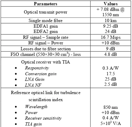
We have carried out a number of measurements by capturing the frequency responses H f of the complete system in the presence of turbulence using a network analyzer. The captured measured frequency responses were compared with the reference frequency response under the turbulence free condition. For each comparison we have taken 100 samples in order to quantitatively compare the similarity between the two plots by means of the normalized standard deviation (STD) and the normalized average values. Fig. 2(a) and 2(b) depicts the normalized STD and the mean values against the carrier frequency for each turbulence scenario. The measured σI2 are 0.05 and 0.34, equivalent to the measured Cn2 of 6.31×10⁻¹¹ and 1.69×10⁻¹⁰ m-2/3, respectively.
For σI2 = 0.05 the mean value of STD is 3 dB changing by ±1 dB while for σI2 = 0.34 we observe a considerable degradation in STD with the mean value of 6.81 dB changing by ± 2 dB. In case of the normalized average of H f we observed similar patterns to Fig. 2(a) with the mean values -7.3 and -11.22 dB for σI2 of 0.05 and 0.34, respectively.
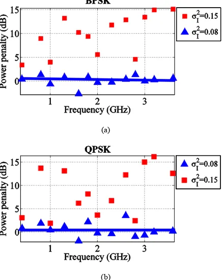
Fig. 3 shows the measured EVM for BPSK and QPSK with and without turbulence. BPSK display lower EVM compared with QPSK except for frequencies > 2 GHz for σI2 = 0.34. For higher turbulence levels both modulation schemes show higher EVMs as expected compared to the no turbulence case. Next we carried out the SNR measurement to determine the power penalties incurred for the system with the turbulence when compared to the link with no turbulence. The measured SNR (and the correspond EVM) from the clear chamber was taken as the reference. For this part we have used two modulation schemes of BPSK and QPSK.
Fig. 4(a) and 4(b) show the power penalties for the RoF-RoFSO link against the carrier frequency range for σI2 of 0.05 and 0.34 for BPSK and QPSK, respectively. Under the weak turbulence regime (i.e. σI2 = 0.08) the variation in the power penalties is relatively small with the mean values of 0.16 dB and 0.46 dB for BPSK and QPSK, respectively. However, for high turbulence levels (i.e. σI2 = 0.34) the power penalties measured is highly random depending on the operating RF carrier frequency. The results clearly demonstrate that the system performance is being affected by the turbulence depending of course on the carrier frequency being used.
(a)
(b)
(a)
(b)
Fig. 2. Statistics of the measuredfrequency responses of the link with turbulence: (a)STD, and (b)average.
IV. CONCLUSIONS
An experimental setup has been used to study the effect of turbulence on a ROF-ROFSO link over the RF frequency range of 0.4 - 4 GHz. It was shown that the proposed system performance was almost the same for the entire frequency range under the weak or no turbulence regimes. Also it was analyzed that higher turbulence levels not only degrade the received optical power levels but also increase its variance. Finally we showed that for proposed system with BPSK and QPSK at different RF carrier frequencies the turbulence effect has marginal impact.
ACKNOWLEDGMENT
This work was supported under the joint research within the frame of EU Cost Action IC1101 OPTICWISE. Publication was supported by the CTU no. SGS14/190/OHK3/3T/13. One of the authors (M. Mansour Abadi) has received a PhD scholarship from Northumbria University, Newcastle, UK.
REFERENCES
[1] Zin A. M., Bongsu M. S., Idrus,S. M., and Zulkifli N., "An overview of radio-over-fiber network technology," in International Conference on Photonics (ICP), pp. 1-3, 2010.
[2] Kazaura K., Wakamori K., Matsumoto M., Higashino,T., Tsukamoto K., and Komaki,S., "RoFSO: A universal platform for convergence of fiber and free-space optical communication networks," in Innovations for Digital Inclusions, K-IDI 2009, ITU-T Kaleidoscope:, pp. 1-8. 2009.
[3] Ming Z., Liang Z., Jing W., Lin C., Cheng L., and Gee-Kung C., "Radio-Over-Fiber Access Architecture for Integrated Broadband Wireless Services," Lightwave Technology, Journal of, vol. 31, pp. 3614-3620, 2013.
[4] Kanesan T., Ng W. P., Ghassemlooy Z., and Lu C., "Theoretical and experimental design of an alternative system to 2x2 MIMO for LTE over 60 km directly modulated RoF link," in Global Communications Conference (GLOBECOM), 2012 IEEE, pp. 2959-2964, 2012.
[5] Ng W. P., Kanesan T., Ghassemlooy Z., and Lu C., "Theoretical and Experimental Optimum System Design for LTE-RoF Over Varying Transmission Span and Identification of System Nonlinear Limit," Photonics Journal, IEEE, vol. 4, pp. 1560-1571, 2012.
[6] Kanesan T., Wai Pang N., Ghassemlooy Z., and Chao L., "Experimental full duplex simultaneous transmission of LTE over a DWDM directly modulated RoF system," Optical Communications and Networking, IEEE/OSA Journal of, vol. 6, pp. 8-17, 2014.
[7] Kazaura K., Wakamori K., Matsumoto M., Higashino T., Tsukamoto, K., and Komaki, S., "A Proposal for a Broadband Wireless Access Technology based on Radio-on-FSO Links," in GLOBECOM Workshops, 2008 IEEE, pp. 1-6, 2008.
[8] Pham Tien D., Shah A. M., Kazaura K., Wakamori K., Suzuki T., et al., "Investigation of suitability of RF signal transmission over FSO links," in High Capacity Optical Networks and Enabling Technologies, HONET 2007. International Symposium on, pp. 1-6, 2007.
[2] Ouchet O., Sizun H., Boisrobert C., de Fornel F. and Favennec P. N., Free-Space Optics: Propagation and Communication: Wiley, 2010. [10] J. Libich and S. Zvanovec, "Influences of turbulences in near vicinity of
buildings on free-space optical links," Microwaves, Antennas & Propagation, IET, vol. 5, pp. 1039-1044, 2011.
[11] A. Mostafa and S. Hranilovic, "In-Field Demonstration of OFDM-Over-FSO," Photonics Technology Letters, IEEE, vol. 24, pp. 709-711, 2012. [12] Naila C. B., Wakamori K., Matsumoto M., Bekkali A., and Tsukamoto
K., "Transmission analysis of digital TV signals over a Radio-on-FSO channel," Communications Magazine, IEEE, vol. 50, pp. 137-144, 2012. [13] Ben Naila C., Bekkali A., Wakamori K., and Matsumoto M.,
"Performance Analysis of CDMA-Based Wireless Services Transmission Over a Turbulent RF-on-FSO Channel," Optical Communications and Networking, IEEE/OSA Journal of, vol. 3, pp. 475-486, 2011.
[14] Pham Tien D., Shah A. M., Kazaura K., Wakamori K., Suzuki T, et al., "A study on transmission of RF signals over a turbulent free space optical link," in Microwave photonics, jointly held with the 2008 asia-pacific microwave photonics conference. mwp/apmp 2008. international topical meeting on, pp. 173-176, 2008.
[15] Hai-Yin H., Wan Chian L., Hoa Le M., Ghassemlooy Z., Yi-Lin Y., and Shien-Kuei L., "2 x 80 Gbit/s DWDM Bidirectional Wavelength Reuse Optical Wireless Transmission," Photonics Journal, IEEE, vol. 5, pp. 7901708-7901708, 2013.
[16] Ghassemlooy Z., Le Minh H., Rajbhandari S., Perez J., and Ijaz M., "Performance Analysis of Ethernet/Fast-Ethernet Free Space Optical Communications in a Controlled Weak Turbulence Condition," Lightwave Technology, Journal of, vol. 30, pp. 2188-2194, 2012. [17] Ghassemlooy Z., Popoola W., and Rajbhandari S., Optical Wireless
Communications: System and Channel Modelling with MATLAB®: Taylor & Francis, 2012.
[18] L. C. Andrews and R. L. Phillips, Laser beam propagation through random media: SPIE Press, 2005.
(a)
(b)