GEOREFERENCING EXPERIMENTS WITH UAS IMAGERY
G. Jóźków*, C. Toth
Satellite Positioning and Inertial Navigation (SPIN) Laboratory
The Ohio State University, Department of Civil, Environmental and Geodetic Engineering, (Jozkow.1, Toth.2)@osu.edu
Commission I, ICWG I/Vb
KEY WORDS: UAS, photogrammetry, positioning, accuracy
ABSTRACT:
Comparing typical airborne mapping systems with Unmanned Airborne Systems (UAS) developed for mapping purposes, there are several advantages and disadvantages of both systems. The unquestionable benefits of UAS are the much lower costs of equipment and the simple operation; though, the regulations to fly UAS greatly vary by country. Low cost, however, means small sensor size and low weight, thus, sensors usually lack the quality, negatively impacting the accuracy of UAS data and, consequently, any derived mapping products. This work compares the performance of three different positioning approaches used for UAS image geolocation. The first one is based on using dual-frequency GPS data, post-processed in kinematic mode. The second approach uses the single frequency, code only GPS data that was acquired and processed by a geotagger, attached to mapping camera. Finally, the third one employs indirect image georeferencing, based on aerial triangulation using ground controls. As expected, the quality of data provided by the inexpensive GPS receiver (geotagger) is not suitable for mapping purposes. The two other approaches provided similar and reliable results, confirming that commonly used indirect georeferencing, which usually assures good solution, can be replaced by direct georeferencing. The latter technique results not only in reduction of field work, e.g. Ground Control Points (GCPs) surveying, but is appropriate for use with other sensors, such as active imaging technology, LiDAR, further extending UAS application potential.
* Corresponding author.
1. INTRODUCTION
Civilian use of UAS is currently of high interest in the mapping community. Ready-to-fly platforms offer large selection of mounts for compact or even Digital Single-Lens Reflex (DSLR) cameras, making them easily operational for taking images to create orthophotos or other mapping products. In comparison to typical airborne mapping systems, UASs are usually constrained to small payload, which, consequently, causes other limitations, such as flight duration, number of sensors and, most importantly, modest sensor quality. On the other hand, the processing of imagery for both systems is nearly identical. In current practice, high-performance aerial mapping systems use GSP/IMU-based direct georeferencing, and the imaging sensor exterior orientation is computed in post-processing mode. Light UAS platforms can mostly carry only a camera, so the sensor orientation is achieved typically by the indirect approach where position and orientation of images is not directly measured during the flight, but computed using GCPs and performing aerial triangulation (AT) or bundle block adjustment. There are several software tools developed that are able to deliver orientation in sufficient accuracy for UAS images (Gini et al., 2013). Usually results obtained by indirect georeferencing are more comprehensive and accurate than that of direct georeferencing. The main advantage of direct measurement of image position and orientation during the flight is the lack of field surveys to collect GCPs. However, there are requirements that must be fulfilled in order to achieve sufficient accuracy. The equipment should contain accurate attitude sensors allowing positioning and orientation of the platform and, subsequently, images. These sensors are typically GPS/GNSS receiver and medium-grade IMU, but other sensors, such as magnetometers and air pressure sensors might be used for
improving the direct georeferencing quality (Pfeifer et al., 2012). Besides the requirements for the sensors performance, other issues apply to direct georeferencing, such as time synchronization between all the sensors as well as boresight misalignment, which are extremely important in high-precision applications.
Recent developments in GNSS and inertial sensors have created a growing interest in direct georeferencing of UAS images. In the case of positioning sensors, light-weight GPS/GNSS receivers and antennas are becoming more affordable; practically, at identical performance level to the ones used in typical airborne mapping systems. Micro-electro-mechanical systems (MEMS) IMU technology has been already widely used for flight control in UAS. MEMS manufactured inertial sensors allowed for strong reduction of size and weight. Until recently, the accuracy parameters have been still worse than those used in typical airborne mapping; MEMS IMUs are characterized by large bias and noise (El-Sheimy, 2009). The newest systems, however, are approaching the tactical grade IMU performance, which is the dominant grade in normal airborne surveying. Some work already proves that MEMS IMU might be suitable for direct georeferencing of UAS images soon (Pfeifer et al., 2012; Chiang et al., 2012; Rehak et al., 2013). Obviously, direct georeferencing is a must for active sensors, such as laser scanners. Beside the accuracy requirements, LiDAR UAS configurations are much more restricted due to payload capacity and, therefore, light-weight and not typically airborne scanners with very limited performance are suitable for small UASs (Lin et al., 2012; Wallace et al., 2012). The potential of LiDAR UAS is recognized by sensor manufacturing companies and dedicated laser scanners with good performance are already available for ISPRS Annals of the Photogrammetry, Remote Sensing and Spatial Information Sciences, Volume II-1, 2014
UAS (Riegl, 2014). However, the weight of such sensors restricts their use onto bigger platforms with larger payload.
This work compares results of positioning UAS images taken with light-weight platform (less than 10 kg) using three different approaches. The first two are using low and high grade GPS receivers and third one uses image bundle block adjustment based on GCPs.
2. EQUIPMENT AND TEST DATA
2.1 Platform
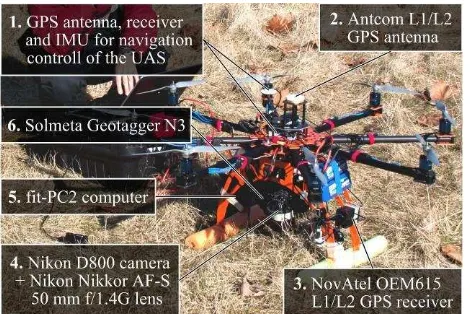
Data collection was performed using a Bergen octocopter, shown in Figure 1, flown in fully autonomous mode based on the planned coordinates of waypoints. Autopilot of the UAS is controlled by single frequency GPS and MEMS IMU data. Note that these two sensors, 1 in Figure 1, are used only for the navigation control of the UAS and their data was not included in any subsequent processing.
Bergen octocopter was designed to fly with most full size DSLR cameras and have the option of using a two-axis camera gimbal or a mount for fixed down-looking orientation.
Figure 1. Bergen octocopter at test site
2.2 Sensor Configuration
To support our investigation of UAS platform positioning for mapping applications, the following sensors were installed on the octocopter:
Nikon D800 36 Mpix camera with Nikon Nikkor AF-S 50 mm f/1.4G lens, 4 in Figure 1.
Dual-frequency GPS receiver, NovAtel OEM615-G2S-B0G-550 (3 in Figure 1) with Antcom Active L1/L2 GPS Antenna, 2 in Figure 1.
Single frequency code GPS receiver for images tagging - Solmeta Geotagger N3, 6 in Figure 1.
Since the software of the Nikon D800 camera allows for taking photos automatically by intervalometer triggering, images were acquired at the shortest available time period of 1 s.
The NovAtel OEM615 is a small, lightweight, high grade GNSS receiver which in the version used in this investigation allowed receiving GPS signals with the maximum rate of 5 Hz during all the test flights. This receiver does not contain any input interface for configuration or internal memory for data
storage, but is fully operational with the software provided by the vendor. Therefore, a small computer, fit-PC2, was mounted on the UAS, 5 in Figure 1, for the parameter setup and GPS data recording.
In addition, a low-grade GPS receiver built into an image tagger was connected to the camera, allowing recording the estimated camera position together with other metadata, such as the number of used satellites, each time when the shutter was released either automatically or manually. This data was stored as image EXIF metadata.
In sensor integration, the sensors’ spatial relationship and the use of common time base are of high importance, therefore, these two aspects need to be discussed in more details. First, the lever arm offset, the position of the GPS antenna phase center in the camera frame must be known. Note the goal of this study is to compare image positions, and thus all coordinates should be reduced to the optical center of the camera. In the case of indirect georeferencing, obviously, there is no need to consider these offsets, as GPS data is not used. For the GPS supported AT, lever arm offsets can be either measured or estimated and considered during adjustment (Ackermann, 1992). Since the Solmeta Geotagger N3 is code based GPS receiver, with 2D accuracy of 3 m, according to specification, the shift between the optical camera center and tagger was not considered, as the distance of a few centimeters to the hot shoe, where the tagger was mounted, was not relevant, as it was much smaller than the positioning error. In contrast, the accuracy of post-processed kinematic positioning based on the NovAtel OEM615 data is expected on the level of a few centimeters, so the larger distance between L1/L2 antenna phase center and camera must be accurately estimated. Approximated values of lever arm offsets for antenna center with respect to the image frame were measured as x = –3 cm, y = –4 cm, and z = 35 cm. Note that beside offsets, the appropriate reduction of GPS recorded position to the camera frame should consider also platform (camera) orientation. Since the IMU data was unavailable and, thus, the measuring of rotation angles was not possible, a simplified solution, which reduces only constant vertical offset z for all camera positions, was used. Note that the multirotor platform used is less stable than fixed-wing aircraft, in terms of maintaining nearly constant vertical orientation, and therefore lower accuracy of the horizontal camera position is expected due to the simplified solution.
The second important aspect of sensor integration is the time synchronization which allows linking images with appropriate GPS recorded positions. The Nikon D800 camera provides an electrical pulse every time when the shutter is released, which is used in image geotagger to estimate the position when the signal from camera is received; the position is stored in the EXIF metadata. Since the NovAtel OEM615 receiver has the external event signal input, the geotagger was modified to split the electrical signal, provided by camera, and then to send it to the dual-frequency GPS receiver as the event input. This way, the GPS time for every camera shutter release is known at around 1 ms accuracy, which is more than sufficient to compute the corresponding image position. There are other issues related to the precise time synchronization of the camera shutter. The optimal time of sending the electrical signal is the middle of the exposure; unfortunately this aspect of the camera signal is unknown to the user. Also delays due to preparing and processing the signal are difficult to estimate. However, these issues seem to be less relevant considering the relatively low ISPRS Annals of the Photogrammetry, Remote Sensing and Spatial Information Sciences, Volume II-1, 2014
speed of the octocopter. Note that during the exposure time of 1/500 s at the UAS speed of 5 m/s, the travelled distance is only 1 cm that is less than the expected accuracy of the kinematic GPS position.
Because the NovAtel OEM615 is not recording GPS data when the electrical pulse from camera is received (only at the programmed constant rate), it might be relevant for the subsequent estimation of camera position how stable is the 1 s period of the camera intervalometer. For a series of 400 images, the GPS time of the electrical signal sent by the camera was recorded. According to the results presented in the Figure 2, the actual time interval is generally shorter than the theoretical 1 s. However, it is compensated after around 90 s where the time interval between certain two frames is longer, say around 1.1 s, that causes that total time of triggering is to be very close to the planned. Due to this instability of time interval during automatic image acquisition, interpolation of image geolocation should consider variable time shift with respect to the GPS recorded epochs.
Figure 2. Difference between theoretical and recorded time of the camera shutter release
2.3 Test Data Acquisition
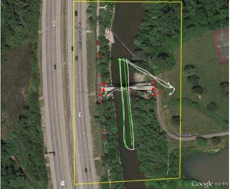
The test flight was performed on January 14th, 2014 over the Olentangy River close to the Broadmeadows Park in Columbus, Ohio. The autonomous flight was planned at the altitude of 135 m AGL with the speed of 4 m/s for two flight lines defined by 4 waypoints. Exposure parameters and focusing distance were set manually and fixed for the entire flight to obtain constant radiometric and geometric properties of the images. During the 4 minute survey, images were acquired in the automatic intervalometer triggered mode with the time period of 1 s. In this setup, the images had end- and sidelap over 90%. The test site is shown in Figure 3.
Figure 3. Test site location including: flight lines (green), actual flight trajectory (white), GCPs position (red), and approximated
image block range (yellow)
In order to perform bundle block adjustment, 31 GCPs located on the bridge and both sides of the river were acquired using GPS RTK technique with 3D accuracy of 5 cm (1).
3. DATA PROCESSING
The camera center positions were computed for 100 images acquired in the autonomous mode in three different ways using:
Dual-frequency GPS data acquired by NovAtel OEM615 receiver.
Data recorded by Solmeta Geotagger N3. AT for the block of 100 images using GCPs.
For the precise calculation of GPS dual-frequency data in differential mode, Continuously Operating Reference Station (CORS) data from the COLB station located 12.7 km away from the test site was used. Additionally, precise GPS ephemerides were used to improve the solution quality. Processing was performed in the RTKLIB v. 2.4.2 software. Number of satellites used to calculate positions was equal to 8 for all epochs. The estimated standard deviation of the position was equal to about 2 cm for horizontal and 2 cm for vertical component. While it is very small, yet it should not be accepted as a true accuracy since the integer ambiguity was not always resolved, resulting in the ‘float’ position which is much more inaccurate than the estimated values. In addition, image positions might be even less precise, because of interpolation, as the images were not taken at the GPS epochs. Note that the GPS data recording rate was equal to 0.2 s equivalent to 0.8 m in distance for the cruising speed of 4 m/s. Since the accurate GPS time of the image acquisition was recorded as an event in the NovAtel receiver, the position of each image was linearly interpolated based on two nearest (in time) positions calculated based on the 5 Hz GPS solution.
The Solmeta Geotagger N3 records WGS-84 Latitude, Longitude and geodetic height in EXIF metadata. Unfortunately, there is no available specification explaining details of calculating geodetic height which probably uses some geoid model for conversion from the GPS computed ellipsoidal height. According to the EXIF metadata, position of photos using geotagger was estimated on the basis of 6 to 9 GPS satellites where the average number of satellites was about 8.
Image positions for the last investigated method were obtained by AT based on 31 GCPs without using any GPS approximated image positions; EXIF data recorded by the geotagger was intentionally cleared, because the software used automatically includes this information as processing inputs. Based on the manually measured GCPs and then the automatically selected and measured 573,025 tie-points, the bundle block adjustment including self-calibration of camera parameters was executed, resulting in calculation of position and orientation of each image. The AT reported an accuracy of 4.7 cm for the object space (ground) and 1.9 pix of the GCPs reprojection error. RMSEs obtained for the GCPs were equal 2.3 cm, 2.7 cm and 3.2 cm for northing, easting and height coordinates, respectively. Large numbers of the GCPs and tie-points as along with small errors suggest that the geolocation of images was correctly estimated.
Coordinates of GCPs and the estimated image centers in the three approaches were converted into the same coordinate ISPRS Annals of the Photogrammetry, Remote Sensing and Spatial Information Sciences, Volume II-1, 2014
system. For horizontal position, the State Plane Coordinate System (SPCS) was used and vertical coordinates were converted into the geodetic heights using GEOID12A model (only for approaches, where conversion from ellipsoidal heights was necessary). This gave the common base for direct comparison of image geolocation.
4. COMPARING IMAGE POSITIONS
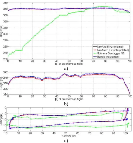
The three sets of image positions are graphically presented in Figure 4, as height profile and horizontal trajectory. Additionally, for the same time range, positions obtained for 5 Hz dual-frequency GPS data are shown; note that heights are reduced already by the vertical offset of 35 cm between the antenna and camera center.
a)
b)
c)
Figure 4. Positions computed; a) height, b) height (without geotagger), and c) horizontal position
Height profile (Figure 4a and 4b) and trajectory (Figure 4c) for the interpolated NovAtel data (1 s) matches quite well with the reference NovAtel data (0.2 s), as expected. Image positions obtained for the dual-frequency GPS data seem to be very realistic; the trajectory is relatively smooth, the hovering areas, and platform rotation after reaching way-points are clearly visible (Figure 4c). Comparing the positions obtained from bundle adjustment and NovAtel data, it is difficult to say which solution is closer to reality. Looking at the trajectories closely, a few single positions from the bundle adjustment seem to be slightly off, as non-smooth trajectory segment was not observed during flight. In terms of horizontal position, the largest differences, an about 1 m, between these two solutions occurred at the end of the autonomous flight (northern part of trajectory). The mean difference of horizontal position between these two solutions was slightly smaller than 0.5 m. Partially, these differences are the results of the simplified approach in reduction of lever arm offset where neither rotation angles nor horizontal offsets were not considered. Comparing vertical positions obtained from dual-frequency GPS data and bundle adjustment, there is a noticeable shift of the mean value equal about 0.3 m (Figure 4b). Note that this shift does not include
vertical offset between the antenna phase center and camera optical center, as this offset of about 35 cm was already removed. This shift seems to be a systematic error which may be explained as a result of inaccurate calculation of GPS positions due to unsolved integer ambiguity. Another more likely reason for this vertical shift might be the errors in the camera self-calibration, particularly wrong estimation of the principal distance. Since there is no air control, therefore camera modeling errors may affect the image positions adjusted in AT. The AT software used provides no error characteristic of the camera calibration process.
Horizontal and vertical positions obtained from the EXIF metadata show that coordinates calculated by the Solmeta Geotagger N3 are very inaccurate, especially for heights, where differences to other solutions were even larger than 70 m (Figure 4a); this, clearly, cannot be accepted even as an approximation for a flying height set to 135 m AGL. In terms of horizontal positions, the differences are smaller and equal to few meters that might be acceptable as initial values for subsequent matching and AT processing. Assuming that the results obtained from dual-frequency GPS data or AT are the reference values, the horizontal error for single frequency code based data is equal to almost 7 m what is much more than the device specified 3 m.
5. BUNDLE BLOCK ADJUSTMENT USING AIR
CONTROLS ONLY
Since the true position and orientation of the images is unknown, the accuracy of image geolocation estimated from dual-frequency GPS data may be evaluated by performing bundle block adjustment with air controls. In this case, the GCPs are used as check points. The results of this bundle adjustment are given in Table 1, listing the RMSE of the air controls and ground check points. Similarly to AT based on GCPs, bundle block adjustment with air controls only included camera self-calibration, but the number of automatically measured tie-points was larger; equal to 845,588.
RMSE Image centers (air controls)
Ground check points
Northing [cm] 22 12
Easting [cm] 16 11
Height [cm] 6 64
Total [cm] 28 66
Reprojection [pix] 0.8 2.2
Table 1. Accuracy of bundle adjustment using air controls only
The total accuracy of 0.3 m for image positions seems to be much worse than the accuracy of AT based on GCPs (4.7 cm). This may be explained by two aspects. First is the unsolved integer ambiguity during GPS data processing, and the second one is the simplified approach of lever arm offset removal where only constant vertical shift between GPS antenna and camera optical center was considered. The lack of IMU data and not including horizontal offsets might explain the larger horizontal than vertical RMSE for air controls. For the relatively large lever arm offset, especially vertical component, significant horizontal shifts need to be considered for the camera position due to platform rotation which might be relatively high for non-fixed-wing UAS. Note the maximal angle difference between vertical and estimated from bundle adjustment camera orientation was 14 degrees.
Horizontal errors assessed at the ground check points are smaller than the errors of image centers. As reported earlier, the vertical shift between image geolocation computed from dual-frequency GPS data and AT is also visible in the bundle adjustment performed using air controls only. All the estimated height differences at the ground check points are negative, resulting in the mean value of –64 cm and the height RMSE is the same (64 cm). Also, reprojection error for check points is small and very similar to that one which was obtained in bundle block adjustment using GCPs. This experiment confirmed that constant vertical shift between camera positions obtained from AT and dual-frequency GPS data was caused by the errors in the camera model. Difference between estimated principal distances during self-calibration using once ground controls, once air controls only, was significant and equal to 0.27 mm (0.5%).
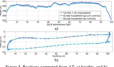
Comparing height profiles (Figure 5a) and trajectories (Figure 5b) obtained for both ATs (ground and air controls) and dual-frequency GPS data, a large similarity can be noticed between the positions of bundle adjustment using air controls and dual-frequency GPS data. This demonstrates strong dependency of bundle adjustment to controls in the used software even when there are a large number of tie-points used.
a)
b)
Figure 5. Positions computed from AT; a) heights, and b) horizontal positions
6. CONCLUSIONS
This work compares three different approaches of UAS image geolocation, including GPS obtained position of dual-frequency carrier-phase receiver, single frequency code based receiver and indirect positioning obtained by aerial triangulation (bundle block adjustment). Results showed that the position of direct geolocation using dual-frequency GPS receiver is very similar to the position obtained from the bundle block adjustment. The quality of direct image geolocation in our tests could be improved obtaining ‘fixed’ GPS solutions by using other software with more efficient algorithm for fixing integer ambiguities or maybe using user reference station located closer to the test site. Integration of GPS and IMU data in a combined solution and strict reduction of lever arm offset would result in more accurate position, especially in the horizontal direction. According to the presented results, high-grade GPS receivers might be used for estimating air controls for bundle adjustment that can be useful in areas where acquisition of GCPs is impossible. Low grade positioning sensors like single frequency code based GPS receiver are unable to improve the quality of UAS mapping.
Small and light dual-frequency GPS receivers open new possibilities for direct georeferencing of UAS images and/or to
support other sensors, such as laser scanners. Improvement of MEMS based IMU sensors in terms of accuracy as well as observed growing miniaturization of LiDAR sensors will further advance the use of UAS technology in mapping. It is expected that in the future the quality of UAS mapping products will compete with that of obtained using high-end airborne systems. Finally, equipping UASs with smaller, but more accurate sensors may significantly increase the cost of equipment comparing to the currently used low cost devices; though, the hardware price will be still more attractive than typical airborne mapping equipment.
REFERENCES
Ackermann, F., 1992. Operational rules and accuracy models for GPS-aerotriangulation. The International Archives of the Photogrammetry, Remote Sensing and Spatial Information Sciences, Vol. 29(B3), pp. 691-700.
El-Sheimy, N., 2009. Emerging MEMS IMU and its impact on mapping applications. Photogrammetric Week, Stuttgart, Germany.
Gini, R., Pagliari D., Passoni D., Pinto L., Sona G., and Dosso P., 2013. UAV Photogrammetry: Block Triangulation Comparisons. The International Archives of the Photogrammetry, Remote Sensing and Spatial Information Sciences, Vol. XL-1/W2, pp. 157-62.
Lin, Y., Hyyppä, J., Jaakkola, A., 2012. Mini-UAV-Borne LIDAR for Fine-Scale Mapping. IEEE Geoscience and Remote Sensing Letters, Vol. 8(3), pp. 426-430.
Pfeifer N., Glira P., Briese C., 2012. Direct georeferencing with on board navigation components of light weight UAV platforms. The International Archives of the Photogrammetry, Remote Sensing and Spatial Information Sciences, Vol. XXXIX-B7, pp. 487-492.
Rehak, M., Mabillard, R., Skaloud, J., 2013. A micro-UAV with the capability of direct georeferencing. The International Archives of the Photogrammetry, Remote Sensing and Spatial Information Sciences, Vol. XL-1/W2, pp. 317-323.
Riegl, 2014. Riegl VUX-1.
http://www.riegl.com/uploads/tx_pxpriegldownloads/DataSheet _VUX-1_02-06-2014_PRELIMINARY.pdf (Accessed July 10, 2014).
Chiang, K. W., Tsai, M. L., Chu, C. H., 2012. The Development of an UAV Borne Direct Georeferenced Photogrammetric Platform for Ground Control Point Free Applications. Sensors (12), pp. 9161-9180.
Wallace, L. Lucieer, A., Watson, C., Turner, D., 2012. Development of a UAV-LiDAR System with Application to Forest Inventory. Remote Sensing (4), pp. 1519-1543.