Used throughout the United States and many other countries, the National Electric Code (NEC) is the world’s most detailed set of electrical codes pertaining to photovoltaic (PV) systems.
Photovoltaic Systems and the National Electric Code presents a straightforward explanation of the NEC in everyday language. The new book is based on the 2017 NEC, which will be used widely until 2023, with most of the interpretations and material staying true long after. This book interprets the distinct differences between previous versions of the NEC and the 2017 NEC and clarifies how these Code changes relate specifically to photovoltaic installations.
Written by two of the leading authorities and educators in the field, this book will be a vital resource for solar professionals, as well as anyone preparing for a solar certification exam.
Bill Brooks is Principal Engineer at Brooks Engineering, Vacaville, USA.
Sean White is a Solar PV professor, trainer and contractor in the USA.
Photovoltaic Systems and the
Photovoltaic Systems and
the National Electric Code
by Routledge
2 Park Square, Milton Park, Abingdon, Oxon OX14 4RN and by Routledge
711 Third Avenue, New York, NY 10017
Routledge is an imprint of the Taylor & Francis Group, an informa business © 2018 Bill Brooks and Sean White
The right of Bill Brooks and Sean White to be identified as authors of this work has been asserted by them in accordance with sections 77 and 78 of the Copyright, Designs and Patents Act 1988.
All rights reserved. No part of this book may be reprinted or reproduced or utilised in any form or by any electronic, mechanical, or other means, now known or hereafter invented, including photocopying and recording, or in any information storage or retrieval system, without permission in writing from the publishers.
Trademark notice : Product or corporate names may be trademarks or registered trademarks, and are used only for identification and explanation without intent to infringe.
British Library Cataloguing-in-Publication Data
A catalogue record for this book is available from the British Library
Library of Congress Cataloging-in-Publication Data A catalog record for this book has been requested ISBN: 978-1-138-08752-1 (hbk)
ISBN: 978-1-138-08753-8 (pbk) ISBN: 978-1-315-11030-1 (ebk)
List of figures vii
List of tables ix
Introduction 1
1 Article 690 photovoltaic (PV) systems 4
2 Article 690 photovoltaic systems part II
circuit requirements 26
3 Section 690.12 rapid shutdown 58
4 Article 690 part III disconnecting means 74
5 Article 690 part IV wiring methods 88
6 Article 690 part V grounding and bonding 103
7 Article 690 part VI to the end of 690 123
8 Article 691 large-scale photovoltaic (PV) electric
power production facility 130
9 Article 705 interconnected electric power
production sources 138
10 Storage articles 168
11 Chapters 1–4, Chapter 9 tables and Informative
Annex C 177
12 PV wire sizing examples 189
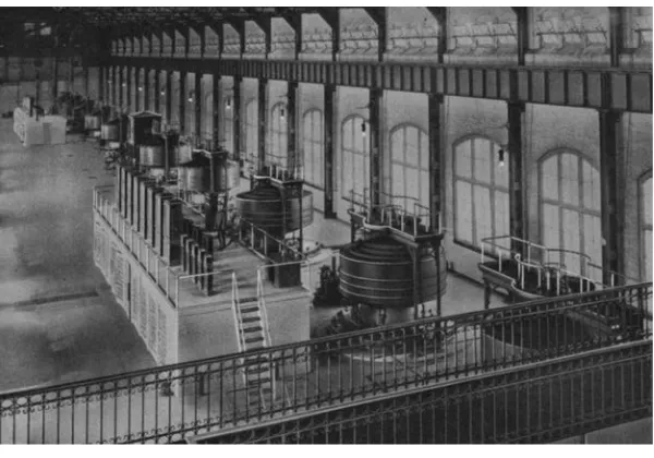
0.1 1895 Niagara Falls power plant 2 1.1 1984 NEC (a much smaller Code book) 5 1.2 2014 NEC Figure 690.1(a) PV power source 8 1.3 2017 NEC PV Figure 690.1(a) PV power source 9 1.4 Interactive system [2017 NEC Fig 690.1(b)] 10 1.5 Ac module system [2017 NEC Fig 690.1(b)] 10 1.6 Dc coupled multimode system [2017 NEC Fig 690.1(b)] 11 1.7 Ac coupled multimode system [2017 NEC Fig 690.1(b)] 13 1.8 Stand-alone system [2017 NEC Fig 690.1(b)] 14 2.1 IV curve with different currents plotted showing
maximum circuit current, which is used for sizing
wires, above and beyond short circuit current 37 2.2 Partial datasheet from outback stand-alone inverter 39 2.3 Module interconnect for multiple parallel-connected
module circuits 47 2.4 Two PV source circuits backfeeding a short on
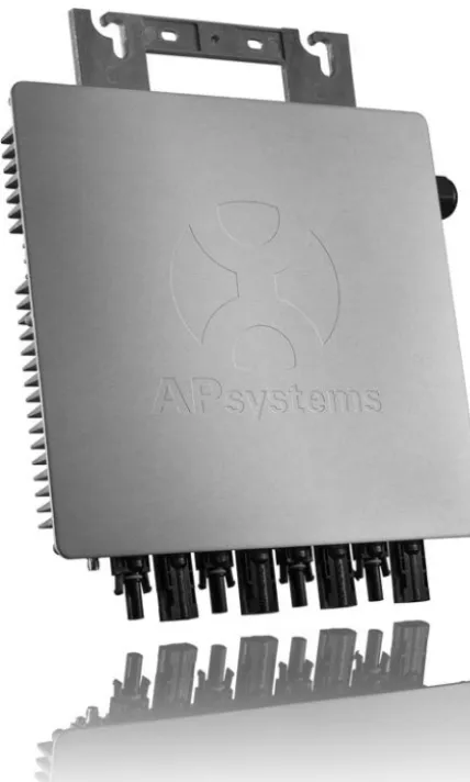
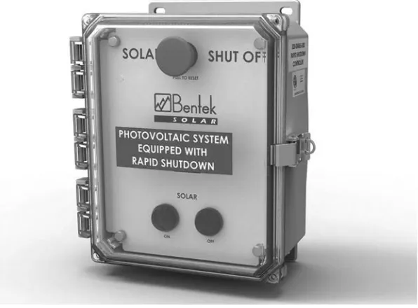
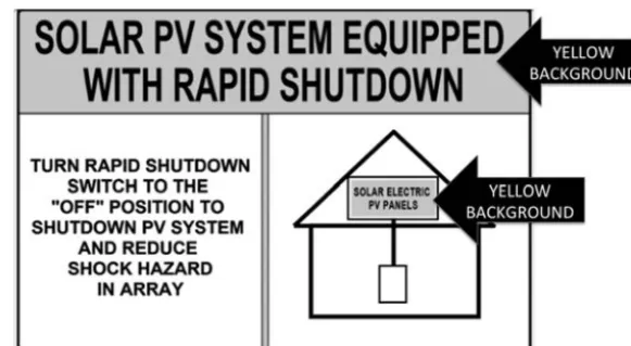
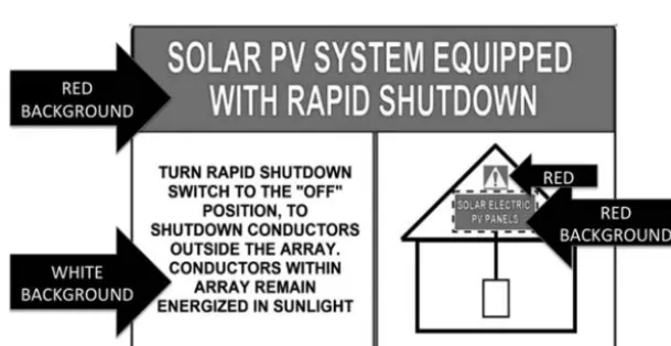
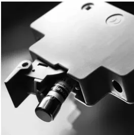
another PV source circuit 53 2.5 Fuses listed for PV 53 2.6 Dangerous dc arc-fault (do not try this at home) 57 3.1 AP system 4 module inverter 63 3.2 Rapid shutdown initiation switch 66 3.3 NEC Figure 690.56(C)(1)(a) reduced array shock
hazard sign 68 3.4 NEC Figure 690.56(C)(1)(b) conductors leaving
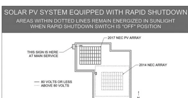
array level rapid shutdown sign 69 3.5 Buildings with more than one rapid shutdown type
6.1 Fuse grounded PV array with one functional grounded conductor 105 6.2 Bipolar PV array 107 6.3 Non-isolated inverter showing ground fault pathway 108 6.4 2017 NEC ungrounded PV array AKA
transformer-isolated inverter 110 6.5 Solidly grounded PV array 111 9.1 Feeder image showing where different parts of the
Code apply to different parts of the feeder 146 9.2 705.12(B)(2)(1)(a) sufficient feeder ampacity 147 9.3 705.12(B)(2)(1)(b) Overcurrent device protecting
feeder 149 9.4 Solar tap rules 150 9.5 25-foot tap rule 152
9.6 100% rule 153
9.7 705.12(B)(2)(3)(b) 120% rule 153 9.8 120% rule with multiple solar breakers acceptable 155 9.9 705.12(B)(2)(3)(c) sum rule 155 9.10 705.12(B)(2)(3)(d) center fed 120% rule 156 9.11 705.12(B)(3) marking label indicating multiple sources 157 9.12 Breakers over 1000V prices 159 12.1 Nicola Tesla demonstrates how to truly understand
2.1 NEC Table 690.7(a) voltage correction factors for
crystalline and multicrystalline silicon modules 30 5.1 Table 690.1(A) correction factors (ambient temperature
correction factors for temperatures over 30°C) 91 5.2 Table 690.31(E) minimum PV wire strands for
Photovoltaic (PV) is growing fast, and the PV material in the National Electric Code (NEC) is changing faster than anything the NEC has seen since the days of Thomas Edison and Nikola Tesla hashing it out over dc vs. ac. It appeared that Tesla was right when 2-phase ac power 1 was installed at Niagara Falls and that ac was the way of the
future, but the future is always unpredictable and with PV, dc is mak-ing a comeback.
This book is designed to relay to the layperson working in the PV industry the NEC PV-related material and changes as simply as pos-sible, but not simpler. We hope that professional engineers (PEs) and sunburnt solar installers alike will comprehend this easy writing style and be entertained just enough to not be bored learning about a Code that has been known to work better than melatonin on a redeye flight. Since this book is about PV, rather than starting at the beginning of the NEC, we will start with the most relevant article of the NEC, which is Article 690 Photovoltaic (PV) Systems ; we will then cover the new Article 691 Large-Scale Photovoltaic (PV) Electric Power Produc-tion Facility which modifies Article 690 for large PV systems and then dive into the interconnections of Article 705 Interconnected Electric Power Production Sources where we understand how PV and other power sources can connect to and feed other power sources, such as the utility grid. The next articles we will cover are the articles on energy storage, which are the old Article 480 Storage Batteries and the new and more relevant in 2017 Article 706 Energy Storage Systems . While we are on the subject of energy storage, we will cover the new Article 710 Stand-Alone Systems (which was formerly 690.10) and this will lead us to another new and renewable themed Article 712 Dc Microgrids . We will then go back to the beginning of the NEC and look at Chapters 1 through 4 of the NEC, which apply to all wir-ing systems, includwir-ing PV. We will see that, in coverwir-ing the new and
Introduction
renewable PV centric articles, we already covered the more important parts of Chapters 1 through 4 used for PV systems and all electric installations, such as Article 250 Grounding and Bonding and Article 310 for wire sizing. There will be many times, when we are covering material in Article 690, that we will go back and forth to other articles, since this is the way to properly use the NEC.
The NEC is updated every three years with a new Code cycle. This edition of Photovoltaic Systems and the National Electric Code reflects the 2017 NEC and will discuss earlier versions of the NEC. When the 2020 NEC comes out, this material will not be obsolete; in fact more than half the PV in the United States is installed in places that adopt the NEC three years after a Code is released. For instance, the state with half of the solar in the US is California, and in Califor-nia, the 2017 NEC is adopted in 2020 and used until the 2020 NEC is adopted in 2023. It is also interesting to note that the proposals for changes to the NEC are crafted three years earlier, so the material in the 2017 NEC was proposed in 2014 and will be used on a regular basis by inspectors until nine years later. Since the equipment changes
Figure 0.1 1895 Niagara Falls power plant
Courtesy Wikimedia
3 so fast in the PV industry, the Code writers intentionally leave parts of the Code open-ended to make way for new inventions that you may come up with, which will save lives and may make you rich.
The 2017 NEC proposals for Article 690 and for other solar-rel-evant parts of the Code were first proposed at meetings at NREL in Colorado in 2014 and put on a Word document by Bill Brooks. This Word document grew, and the proposals were refined with a lot of input. These future Codes were later proposed to the top dogs at the National Fire Protection Association by Ward Bower (inventor of the grid-tied inverter) and Bill Brooks of NEC Code Making Panel 4 in Hilton Head, North Carolina.
Now is the time to take out your 2017 NEC and follow along to understand PV and the NEC.
Note
Article 690 first came out in a little book known as the 1984 NEC and has been updated and mostly lengthened ever since.
In comparing the original 1984 version of Article 690 to today’s NEC, there are many similarities yet also quite a few differences. Time to dig in!
Let us first list what we are dealing with in Article 690 before we dig deep. This will give us perspective and familiarize us with how to look things up quickly.
The NEC is also known as NFPA 70 and is divided into Chapters, then Articles, then Parts and Sections.
For example, rapid shutdown requirements are found in: NEC Chapter 6 Special Equipment
Article 690 Solar Photovoltaic (PV) Systems Part II Circuit Requirements
Section 690.12 Rapid Shutdown of PV Systems on Buildings Here is what we find in Article 690:
Article 690 solar photovoltaic (PV) systems Part I general (part)
690.1 Scope [Section 690.1]
690.2 Definitions [There are more NEC definitions in Article 100, such as the definitions for PV, ac and dc.]
690.4 General Requirements [They could not come up with a bet-ter title for this category.]
690.6 Alternating Current (ac) Modules
Article 690 photovoltaic (PV)
systems
5
Part II circuit requirements
690.7 Maximum Voltage 690.8 Circuit Sizing and Current
690.9 Overcurrent Protection [Article 240 is also Overcurrent Protection.]
690.10 Stand Alone Systems [This has been moved to Article 710 in the 2017 NEC.]
Figure 1.1 1984 NEC (a much smaller Code book)
690.11 Arc-Fault Circuit Protection (Direct Current)
690.12 Rapid Shutdown of PV Systems on Buildings [Big changes] Part III disconnecting means
690.13 Photovoltaic System Disconnecting Means 690.15 Disconnection of PV Equipment
Part IV wiring methods
690.31 Methods Permitted
690.32 Component Interconnections 690.33 Connectors
690.34 Access to Boxes
Part V grounding and bonding [Article 250 is also grounding and bonding.]
690.41 System Grounding [Big changes in the 2017 NEC] 690.42 Point of System Grounding Connections
690.43 Equipment Grounding and Bonding 690.45 Size of Equipment Grounding Conductors 690.46 Array Equipment Grounding Conductors
690.47 Grounding Electrode System [Experts argue over a lot of this article, which is interesting to observe.]
690.50 Equipment Bonding Jumpers Part VI marking
690.51 Modules
690.52 Alternating Current Photovoltaic Modules 690.53 Direct Current Photovoltaic Power Source 690.54 Interactive System Point of Interconnection
690.55 Photovoltaic Systems Connected to Energy Storage Systems 690.56 Identification of Power Sources [This includes new Rapid
Shutdown signs.]
Part VII connection to other sources
690.59 Connection to Other Sources [Directs us to Article 705] Part VIII energy storage systems
7 Now it is time to dive into the detail of Article 690.
Article 690 solar photovoltaic (PV) systems Part I general (part)
690.1 scope (section 690.1)
Word-for-word NEC:
“690.1 Scope. This article applies to solar PV systems, other than those covered by Article 691, including the array circuit(s), inverter(s), and controller(s) for such systems. [See Figure 690.1(a) and Figure 690.1(b).] The systems covered by this article may be interactive with other electrical power production sources or stand-alone or both, and may or may not be connected to energy storage systems such as batteries. These PV systems may have ac or dc output for utilization.
Informational Note: Article 691 covers the installation of large-scale PV electric supply stations.”
Discussion: For the most part 690.1 is self-explanatory, however, if we read the 2014 and the 2017 NEC carefully, we will notice that energy storage systems (batteries) are no longer part of the PV system.
2017 NEC language:
“may or may not be connected to energy storage systems.” 2014 NEC language:
“may be interactive with other electrical power production sources or stand-alone, with or without electrical energy storage such as batteries.”
It takes some careful analysis of the language, but we see that being connected to batteries in the 2017 NEC is different than with batteries in the 2014 NEC.
Figure 1.2 2014 NEC Figure 690.1(a) PV power source
Courtesy NFPA
Next, we see diagrams that will show us the dividing line between the PV system and not the PV system.
Section 690.1 also has some figures that we can look at in order to get a picture of what we are talking about.
Figure 1.2 is an image from the 2014 NEC. Figure 1.3 is an image from the 2017 NEC.
9
Figure 1.3 2017 NEC PV Figure 690.1(a) PV power source
Courtesy NFPA
Images are good to learn from. Next, we will go over the different images in Figures 690.1(B), paying close attention to the various PV system disconnecting means, which separate the PV system covered here in Article 690 from systems covered in other areas of the 2017 Code. Remember, much of this has changed in the 2017 NEC.
Interactive (grid-tied) inverter circuits are very simple. The inverter is used only for PV power; it has no other purpose and therefore is part of the PV system.
A big question installers have is: “What is the difference between an ac module and a microinverter bolted to a PV module?” The answer is that if the PV module was listed to UL1703 while the inverter was bolted to it and the inverter was tested and listed to UL 1741 while bolted to the PV module, then it is an ac module and we do not consider dc part of the product when installing this module.
Figure 1.4 Interactive system [2017 NEC Fig 690.1(b)]
Courtesy NFPA
Figure 1.5 Ac module system [2017 NEC Fig 690.1(b)]
11
There is a lot of information in Figure 1.6 . First of all, dc coupled and multimode are different things, which can go together. A dc cou-pled system is a PV system that is typically charging batteries with a charge controller connected to a PV array. The inverter in a dc cou-pled system will be coucou-pled with the inverter and the charge controller working with dc voltage. In fact, it is possible to have a dc coupled system that does not have an inverter, but most people would like to utilize ac electricity with their dc coupled systems.
As we can see in the 690.2 Definitions that we are about to dive into, a multimode inverter is an inverter that can work in different modes, such as stand-alone (off-grid) and interactive (grid-tied). This type of inverter was also known as a bimodal inverter for a time and will have different outputs. One output will go to the stand-alone (backed up) loads and the other output will go to the loads that are not backed up and to the grid. When the power goes down, the interactive output of the inverter
If the module and microinverter were not listed together, then we are responsible for applying the NEC to the dc circuit going from the module to the inverter. It is also interesting to note that the word microinverter does not appear in the NEC. The NEC looks at a microinverter as nothing more than a small (micro) inverter.
Figure 1.6 Dc coupled multimode system [2017 NEC Fig 690.1(b)]
will act exactly as an interactive inverter and anti-island (stop sending voltage or current to the grid). No interactive inverter circuit is allowed to be an “island of power” and must disconnect from the grid.
Multimodal vs. hybrid
There is often confusion about multimodal inverters and hybrid PV systems.
A hybrid system is defined in Article 100 Definitions as, “A sys-tem comprised of different power sources. These power sources could include photovoltaic, wind, micro-hydro generators, engine-driven generators, and others, but do not include electric power production and distribution network systems. Energy storage sys-tems such as batteries, flywheels, or superconducting magnetic stor-age equipment do not constitute a power source for the purpose of this definition.” What we are saying here is that being connected to the grid has nothing to do with being hybrid. Hybrid has to do with having multiple sources of power, not including energy stor-age or the grid. A multimodal system is, as we have mentioned, one that can work in grid (interactive) or off-grid (stand-alone) mode.
Ac coupled systems are becoming more popular. There are argu-ments on each side, whether it is best to add energy storage to PV systems via ac coupled and dc coupled systems (or both). Ac coupled systems have the benefit of being able to use regular grid-tied inverters in the system and the drawback of having two kinds of inverters.
13
Figure 1.7 Ac coupled multimode system [2017 NEC Fig 690.1(b)]
Courtesy NFPA
beneficial to do so because of utility demand charges, time-of-use rate schedules or because in some places, utility customers are not allowed to export energy.
The stand-alone system in the image above has a few differences with the average stand-alone system we see in the field. First of all, there is usually a charge controller that is connected to three different things. First is the PV array, second is the energy storage system and third is the inverter. These days, it is unusual to have dc loads as shown in Figure 1.8 .
Figure 1.8 could also be considered a dc coupled system without a multimode inverter.
690.2 definitions
Because this book is meant to be read with an actual NEC book handy or to be read by someone already familiar with the NEC, we will not repeat every easy to understand definition in Article 690. We will repeat the language of some of the newer and more difficult to under-stand definitions that a solar professional will have a tendency to use in their career. We will also add discussion to some definitions.
Alternating current (ac) module
At NREL in 2014, Sean and Bill made a proposal to require lithium batteries for bipolar arrays for the 2017 NEC, but everyone just laughed at them.
Figure 1.8 Stand-alone system [2017 NEC Fig 690.1(b)]
Courtesy NFPA
to a module?” The answer is that the ac module has the microinverter attached to it before it goes through the UL 1703 PV testing and the UL 1741 inverter testing (also see Figure 1.5 , page 10 of this book).
Bipolar photovoltaic array
Discussion: A bipolar PV array is dc power analogy of 120/240Vac power on a house in the US. In a bipolar system there is a positively grounded array section and a negatively grounded array section on the same inverter. This means that we can have voltage to ground that is half of the total voltage that the inverter is getting the benefit of processing. The interesting thing about this, in the 2017 NEC, is that with the 1500Vdc to ground equipment, we can have an inverter with a 3000Vdc input in a ground mount PV system!
15 Dc-to-dc converter
Discussion: The dc-to-dc converter definition was put into the Code in 2014 and first put into a diagram in the 2017 NEC. The defini-tion is left rather wide open, so that new equipment not yet in use or invented can be put into use and save lives. For instance, the diagram shows dc-to-dc converters connected to PV source circuits and then the dc-to-dc converters are connected to each other in parallel to make a dc-to-dc converter output circuit. The way we usually see it in prac-tice, at the publication of this book, is with the dc-to-dc converters connected to one PV module per optimizer and then the optimizers are connected together in series and then connected to the inverter. There are some optimizers that work almost the same, but with two modules in series. These optimizers with two modules in series may not comply with module level shutdown requirements that we will learn about when we get to 690.12 Rapid Shutdown . (In 2019, the 2017 NEC may require module level shutdown unless other products are made avail-able that provide similar safety benefits).
Power optimizers
Dc-to-dc converters are commonly referred to in the industry as “power optimizers,” which is really a marketing term. If a dc-to-dc converter did not work as well as advertised or was clipping power (reducing power on purpose), perhaps we would call it a “power-pessimizer.”
Dc-to-dc converter source and output circuits
Discussion: Dc-to-dc converter source and output circuits, which are new terms in the 2017 NEC, are like PV source and PV output circuits, however, they are dc-to-dc converters connected together rather than PV modules. Just like how PV modules connected together in series are a PV source circuit, dc-to-dc converters connected together in series are a dc-to-dc converter source circuits.
String theory
Dc-to-dc Converter Output Circuits are dc-to-dc Converter Source Circuits connected together in parallel and could be connected together in a combiner . Dc-to-dc Converter Output Circuits are uncommon, however, the NEC gurus thought it important enough to define and to let the future decide what circuits will be used.
Diversion charge controller
Discussion: A diversion charge controller will divert charge from a battery to prevent the battery from getting overcharged. A diversion charge controller will often send the excess energy to a diversion load, such as a pump or a heating element in a hot water heater. Also included in this definition of a diversion load is sending energy back to the grid, so if we have a grid-tied battery-backup PV system, when the batteries are charged, we will divert the excess energy to the grid. Electrical production and distribution network
Discussion: This is a fancy name for a grid, which can be a big utility grid or a smaller micro-sized grid such as a groovy college campus. Functional grounded PV system
One of the biggest theoretical changes in the 2017 NEC for PV turns everything we formerly thought we knew about PV system grounding upside down or we should say right side up!
standards. Since everyone in the industry is calling PV source cir-cuits “strings,” would it be acceptable to call dc-to-dc converter source circuits “strings”? Perhaps it is as correct as calling a PV source circuit a “string.”
On another note, I often hear installers calling microinverters that are connected together on a circuit a “string.” I am always correcting the microinverter “string” concept and calling it a “branch” rather than a “string,” since microinverters connected together are generally connected in parallel, like a branch circuit, and do not have that “series-string thing” happening.
17 From now on, common interactive inverters that are either system grounded via a fuse (old-style formerly known as grounded) and sys-tems that are transformerless (formerly known as ungrounded) and do all their magic through electronics in the inverter are hereby consid-ered functionally grounded inverters !
Let’s talk about the “formerly known as grounded” fuse grounded inverters first (may Prince rest in peace). These inverters are system grounded through a fuse. This means that usually a negative, but sometimes a positive dc busbar in the inverter is connected to the ground busbar via a fuse. When enough current goes through the ground wire during a ground fault, then the fuse blows and suddenly the grounded conductor becomes ungrounded. So in this type of system when there is a ground fault, what has been white to indicate it is a grounded conductor may be ungrounded when we are working on it. This previously (no more) required us to have a sign telling us that if a ground fault is indicated, then the grounded conductor may be energized. This is a very confusing label to someone who is not familiar with PV systems. Electricians are used to white-colored grounded conductors to be near ground potential! (Remember: a grounded conductor is a current-carrying conductor that has the same voltage as ground due to a single point of system grounding).
These “formerly known as grounded” inverters had a problem. Large PV systems would often have a few milliamps per module of leakage currents taking the parallel fuse pathway home to the nega-tive bus as some of the electrons took the path through glass, frames, cables, insulation and rails when there were no ground faults. As the system became larger, the leakage became greater and the immediate cure was to upsize the ground fault detection and interruption (GFDI) fuse. With a larger GFDI fuse and a foggy day, some systems would not be able to catch a real ground fault. Even without a foggy day a ground fault that was not severe would stay hidden and the system would keep on making good, clean solar energy. Then what would happen in a few cases is the dangerous outcome. A second ground fault would occur and we have what in tennis they call a double fault. An entire array can get short-circuited and start backfeeding through a single string and poof, smoke and the rest we will leave up to your imagination before someone uses this against us in court.
have a reference point to ground related to the internal workings of the inverter, but do not have a grounded conductor. We used to call these inverters European inverters, since having something ungrounded on your house was historically an AHJ no-no in the United States. Then after some modernization, a few puffs of smoke (not a pun) and some explaining, these formerly known as ungrounded inverters soon became the safer norm. After all, they are safer, cheaper and more effi-cient; safer being the key. These inverters can detect ground faults that are way less than the other inverters. Every day these modern inverters do insulation testing on the PV circuits. They are very sensitive and can detect minor ground faults.
With all of this being said, it is still possible to have a solidly grounded PV array; it’s just not common in the modern era. Perhaps you have a small PV system running a water pump. Your PV array negative might be solidly connected to a ground rod. That would be a solid ground and it would be safe to say that the system is more than “functionally” grounded.
The term functional grounding was taken from Europeans by someone on NEC Code Making Panel 4. “Hey Bill, the Europeans called and they want their functional grounding back!”
Because most of our PV systems are functionally grounded sys-tems, we have a new set of rules that covers all of these functionally grounded systems. No more white negatives (or positives), no more required PV wires (USE-2 is good), no more fuses on two polarities and opening positive and negative in the dc disconnect are required to be functional. We will cover this again as soon as you almost forget it and force it into your long-term memory when we get to the meat of Article 690.
Generating capacity
19 Interactive system
Discussion: On the street, they call this a grid-tied system.
Perhaps because of the fact that an ac coupled PV system can use interactive inverters, we have to use this fancy term to describe a grid-tied inverter without a grid. In a way, an ac coupled system battery inverter will trick an interactive inverter into thinking there is a grid to turn on the interactive inverter. That is a tricky battery inverter that is not interactive, yet interacting with an interactive inverter to turn it on. We might call this true sine wave inverter coupling love!
Interactive inverter output circuit
Discussion: This term is new in the 2017 NEC and differentiates this circuit from a battery inverter output circuit. Just like it sounds, an interactive inverter output circuit consists of the ac conductors com-ing out of an interactive inverter. Battery inverter output circuits have different characteristics and now we have different terms for these dif-ferent circuits.
Multimode inverter
Discussion: A multimode inverter can work in interactive mode or it can work in stand-alone mode. A multimode inverter will have differ-ent outputs for the interactive and stand-alone circuits. A multimode inverter has also been called a bimodal inverter in some books. Often multimode inverters are incorrectly called hybrid inverters. Inverters may not be hybrid. A hybrid PV system will have another source of power besides PV, such as a generator.
Solar panels vs. solar modules
Everyone outside of the NEC realm, including the President of the United States, calls a solar module the slang term “solar panel.” A solar panel according to the NEC is a group of solar modules that are connected together before being installed. In fact, most solar installers today have never installed an NEC defined “solar panel.”
PV source circuit
A PV source circuit consists of PV modules connected together in series, which is commonly referred to as a string.
PV output circuit
If PV source circuits are connected together in parallel at a dc com-biner, then the output of the combiner is defined as a PV output circuit.
Discussion: Most PV systems on buildings these days have PV source circuits that go straight to the inverter and avoid having PV output circuits and dc combiners. There are also large GW scale PV systems that use “string inverters” and avoid having PV output circuits and combiners.
Benefits of not having PV output circuits/dc combiners: 1 There is no need for a dc combiner.
2 There are no dc combiner fuses.
3 If one or two strings are going to a single MPP, which is commonly the case, then no dc fuses are needed.
4 Having strings go straight to the inverter puts the dc arc-fault pro-tection at the inverter, which is more convenient than having elec-tronics detect dc arc-faults at dc combiners.
21 String inverters are becoming more popular at the expense of central inverters for the reasons mentioned above. Some people think that large central inverters will go out of style completely. The authors of this book will remain neutral and let the economics decide.
MPP or MPPT = maximum power point (tracking)
Most modern string inverters have multiple inputs. These inputs are connected to separate dc-to-dc converters in the inverter. This means that different PV source circuits or groups of PV source circuits can operate at the perfect voltage for power production. This way different PV source circuits can have different numbers of modules or bypass contributions from shaded modules through the bypass diodes in the modules. Additionally monitoring and dc arc-fault protection is easier. In the early days before MPPTs, it was a solar sin to have different numbers of modules on different source circuits on the same inverter. Now we have different inverter inputs that can operate independently of each other.
Photovoltaic power source
NEC wording: “An array or aggregate of arrays that generates dc power at system voltage and current.”
Discussion: With the advent of dc-to-dc converters and multi-input inverters the definition of Photovoltaic Power Source is more compli-cated. I would say that with optimizers and microinverters, each set of module conductors can be working at a different voltage and some might view these as separate PV power sources. However, a better way to view these separate circuits is to call them PV source circuits. An inverter with three different source circuits connected to three separate inputs would have no PV output circuit.
Photovoltaic system dc circuit (new in 2017)
NEC wording: “Any dc conductor supplied by a PV power source, including PV source circuits, PV output circuits, dc-to-dc converter source circuits, or dc-to-dc converter output circuits.”
Stand-alone system
Synonym: Off-grid or possibly optional standby system (Article 702) Note: Stand-alone systems moved from 690.10 to new Article 710 Stand-Alone Systems in the 2017 NEC.
690.4 general requirements
Outline of 690.4 general requirements 690.4 General Requirements
690.4(A) Photovoltaic Systems 690.4(B) Equipment
690.4(C) Qualified Personnel 690.4(D) Multiple PV Systems 690.4(E) Locations Not Permitted
One of the more difficult things for someone learning to use the NEC is to remember to know where to look for something. This book is going to do its best to outline, organize, point and discuss topics, so that the reader will be more familiar with and have a better idea where to find what you are looking for.
Section 690.4 General Requirements, which is in Part I General of the NEC is not very memorable and it is going to stump a few people who are looking for this information, so let us state the obvious and dive into these General Requirements. For whatever reason you can make something catch your attention, it will help you remember it.
690.4(A) photovoltaic systems
In plain English: PV systems can supply a building at the same time as other sources of power.
Discussion: If you live in coal country and the AHJ refuses to let you put those sunbeam electrons into the grid, you can support your argument here.
690.4(B) equipment
Equipment that needs to be listed (or field labeled) for PV applications according to 690.4(B):
Inverters (UL 1741)
23 PV Modules (UL 1703)
PV Panels [Products have been built that panelize modules and have been listed when shipped that way. Solyndra solar panels were a group of tubes, each being a module, that were listed and shipped with multiple tubes on a rack creating a solar panel and listed to UL 1703].
Ac Modules [UL 1703 and UL 1741 tested as a unit] Dc Combiners (UL 1741)
Dc-to-dc Converters (UL 1741) Charge Controllers (UL 1741)
Discussion of listed and field labeled equipment: Listed products are found on a list of certified products that various certification labs develop. Field labeled products may not be on one of these lists but get evaluated by a certification lab who puts a label on the product after it has met whatever test requirement was requested to be tested.
An informational note on informational notes:
Informational notes in the NEC are good ideas, but not requirements. Just like a yellow speed sign tells you it is a good idea to slow down for a corner, an informational note gives you good advice. Informational notes used to be called fine print notes and abbreviated FPN.
690.4(C) qualified personnel
What it means: Installation of equipment and wiring should be done by “qualified personnel.”
There is an informational note that tells us that we can look to Article 100 Definitions to see the definition of qualified person . Article 100 Qualified Person Definition: One who has skills and knowledge related to the construction and operation of the electrical equipment and installations and has received safety training to recognize and avoid the hazards involved.
690.4(D) multiple PV systems
What it means: multiple PV systems are allowed on a single building. If multiple PV systems on a building are located away from each other, then there must be a directory at each PV system disconnecting means showing where the other disconnecting means are located in accordance with 705.10 directory .
Discussion: We do not want firefighters thinking they turned off all of the PV on the building when they hit one of the disconnects on the building, not knowing that there are other disconnects that will turn off other PV systems at a different location on the building. Tricking of firefighters or utility workers is not cool nor is it allowed.
Disconnecting means means . . .
Like you would think, a PV system disconnecting means is an off switch for a PV system. A disconnecting means is what separates a PV system from the rest of the electrical system. A PV system disconnecting means for an interactive (grid-tied) inverter would be on the ac side of the inverter, separating the PV system from what is not the PV system. Study PV system disconnect in Fig-ures 1.4 through 1.8 earlier in this chapter on pages 10 through 14 and also in the NEC Figure 690.1(B) Images.
We generally have one PV system disconnecting means and several equipment disconnects for a PV system. Complicated dc PV systems could have more than one PV system disconnecting means, but they have to be grouped for each system.
690.4(E) locations not permitted
PV equipment and disconnecting means are not allowed in bathrooms just in case you had your heart set on mounting one next to your toilet – sorry, not allowed.
Think of “wet feet” and getting shocked.
690.6 alternating-current (ac) modules
Outline of 690.6 alternating-current (ac) modules 690.6 Alternating-Current (ac) Modules
25 Discussion: 690.6 is stating the obvious.
690.6(A) PV source circuits
What it means: ac modules are tested and listed as a unit, so we do not need to consider any dc circuits, such as PV source circuits.
It is interesting to note that, with a microinverter, we consider the dc conductors between the module and the inverter a PV source circuit, but not with an ac module.
690.6(B) inverter output circuits
It says: The output of an ac module is considered an inverter output circuit.
Part II circuit requirements
690.7 Maximum Voltage 690.8 Circuit Sizing and Current
690.9 Overcurrent Protection [Article 240 is also Overcurrent Protection]
690.10 Stand Alone Systems [moved to Article 710 in the 2017 NEC]
690.11 Arc-Fault Circuit Protection (Direct Current)
690.12 Rapid Shutdown of PV Systems on Buildings [big changes]
690.7 maximum voltage
Understanding 690.7 sets true solar professionals apart from the solar un-professionals. Understanding calculations using 690.7 is also very important to NABCEP, as reflected in their exams.
Outline of 690.7
690.7 Maximum Voltage
690.7(A) Photovoltaic Source and Output Circuits
690.7(A)(1) Instructions in Listing or Labeling of the Module 690.7(A)(2) Crystalline and Multicrystalline Modules 690.7(A)(3) PV Systems of 100kW or Larger
690.7(B) Dc-to-dc Converter Source and Output Circuits 690.7(B)(1) Single dc-to-dc Converter
690.7(B)(2) Two or More Series Connected dc-to-dc Converters
690.7(C) Bipolar Source and Output Circuits
Article 690 photovoltaic
systems part II circuit
requirements
27 Electricians are used to having the grid as the voltage or a device that has a factory set voltage output. With PV, we have a lot of variables.
690.7(A) photovoltaic source and output circuits
PV source and output circuits get their voltage directly from series con-nected solar cells. The NEC will consider two factors that increase PV source and output circuit voltage. First of all, putting modules in series increases the voltage . Secondly, cold temperature increases the voltage .
PV output circuits are PV source circuits connected together in par-allel at a dc combiner . Since voltage is determined by series connec-tions and not parallel connecconnec-tions, PV output circuits have the same voltage as the PV source circuits that are combined to make the PV output circuit . From here on out, we will just talk about PV source circuit voltage and understand that the PV output circuit has the same voltage as the PV source circuits that feed it.
Multiple MPPT inverters
Most modern string inverters have multiple Maximum Power Point Trackers (MPPTs). Each MPPT is an electrically separate input that can and will operate at a different voltage from other inputs on the same inverter. Different inputs are electrically treated from a PV designer point of view at the inputs as if they were different inverters. An inverter with two PV series strings per input will not require fuses on the inputs. An inverter with three PV source circuits on one input will typically require fuses.
690.7(A) informational note
An informational note is a good idea (not a requirement) and the NEC tells us that a good place to find cold temperature data that we can use in determining voltage for locations in the United States is the ASHRAE Handbook. A very convenient place to find this data is at the website for the Expedited Permit Process: www.solarabcs.org/permitting.
The 2017 NEC gives us three ways to determine voltage and we can make a choice of which method we will use. These methods will result in different values of voltage, depending on the method we chose to use. The three methods for determining PV source circuit (string) voltage are:
690.7(A)(1) Calculations 690.7(A)(2) Table 690.7(a)
690.7(A)(3) Engineering supervision
690.7(A)(1) voltage temperature calculation method
The 690.7(A)(1) method is the most common method used by solar professionals for determining PV source circuit (string) voltage. This method is also required for anyone taking any NABCEP PV exam.
In order to calculate the module maximum voltage, you will need three things:
1 Voc (open-circuit voltage) 2 Temperature coefficient of Voc 3 Low temperature
Module Voc and temperature coefficient of Voc is most commonly found on the PV module manufacturer’s datasheet. Low temperature data is most easily found on www.solarabcs.org.
of Energy. On the left side of the www.solarabcs.org webpage, click on Expedited Permit Process and then click on “map of solar reference points” to find the low temperature data to use for calculating voltage. This webpage also has high temperature data that can be used for wire sizing, which we will cover later in this book.
29 Let us run through a PV source circuit maximum voltage calculation using a simple example with round numbers.
Example:
1 Cold Temp = −5°C
2 Temp. Coef Voc = −0.3%/°C 3 Voc = 40V
4 Number of modules in series = 10 Calculation:
1 Determine delta T (difference in temperature) from Standard Test-ing Conditions (STC)
a All PV modules are tested at STC = 25°C
b The difference between −5°C and 25°C is 30°C or − 30°C 2 Multiply delta T by Temp. Coef. Voc
a 30°C × 0.3%/°C = 9% increase in voltage
b Another easier method converts percent to decimal first i 30°C × 0.003 = 0.09
3 Add 1 to figure above to get 109% increase in voltage
a 0.09 + 1 = 1.09
i This figure is a temperature correction factor
4 Multiply the temperature correction factor by Voc at STC to get cold temperature Voc
a 1.09 × 40V = 43.6V = maximum voltage for one module 5 10 in series × 43.6V = 436V maximum voltage for the PV source
circuit (string)
When practiced, the method above can be done in 10 seconds by fast calculator users. If you practice this 10 times fast, you will be an expert. This method can be done easily with a calculator and without writing anything down.
On the calculator keypad, press:
25 + 5 = 30 (if the 5°C were above zero then subtract 5 from 30 to get 20)
.09 + 1 = 1.09
1.09 × 40 = 43.6V = maximum voltage
Often we do string sizing with this number, which means we divide it into the inverter maximum input voltage and then round down to get the maximum number of modules in series without going over voltage.
Example using 43.6V maximum voltage and 450V inverter:
450V/43.6V = 10.3
10 in series is the maximum number in series without going over voltage (always round down here).
In this example, if we have 10 in series, then the maximum system voltage is:
10 in series × 43.6V = 436V = maximum system voltage
It is very common for solar un-professionals to incorrectly write that the maximum system voltage is 450V on the label on the dc disconnect in this example, which is incorrect. 436V is correct.
Once practiced, you should be able to do this calculation without paper using a calculator in less than a minute. The world record is 17.1 seconds. 690.7(A)(2) table method
Table 2.1 NEC Table 690.7(a) voltage correction factors for crystalline and multicrystalline silicon modules
Correction factors for ambient temperatures below 25°C (77°F) (Multiply the rated open-circuit voltage by the appropriate correction factor shown below.)
31 Using Table 690.7(a) is easier than performing the 690.7(A)(1) Volt-age Temperature Calculation Method . We can consider this optional method a shortcut; however, in some cases, we will have more options for more modules in series using the 690.7(A)(1) method. The 690.7(A) (2) method using Table 690.7(a) is more conservative and will come up with a slightly higher module voltage every time.
We use Table 690.7(a) by cross-referencing a temperature with a temperature correction factor . We then multiply the temperature cor-rection factor by the module open-circuit voltage to get the module maximum voltage.
Let us use the 690.7(A)(2) method using Table 690.7(a), using the same numbers that we just used in the 690.7(A)(1) calculation exam-ple, however, this time we will not use the module manufacturer’s tem-perature coefficient for open-circuit voltage.
Example:
1 Cold temp = −5°C 2 Voc = 40V
3 Number of modules in series = 10 Calculation using Table 690.7(a)
1 Looking at Table 690.7(a) at −5°C, we can see that −5°C corre-sponds with a temperature correction factor of 1.12 (12% increase in voltage)
2 Multiply 1.12 × 40V and get 44.8V
3 10 in series × 44.8V = 448V maximum system voltage
We can see, by the results of comparing the 690.7(A)(1) calculation method to the 690.7(A)(2) table method , that the 690.7(a) table method resulted in a higher voltage that is very close to the 450 inverter maximum voltage.
If it were 1 degree colder at −6°C we would still be able to have 10 in series with the 690.7(A)(1) calculation method , but we would have gone over voltage using the 690.7(A)(2) table method using Table 690.7(a).
We can see that at −6°C in Table 690.7(a) we have a temperature correction factor of 1.14.
40V × 1.14 = 45.6V
690.7(A)(3) engineering supervision method for calculating maximum voltage for PV systems over 100kW generating capacity (ac system size). New in 2017 NEC
Under engineering supervision, there can be alternative ways of doing things throughout the NEC. According to 690.7(A)(3), a licensed pro-fessional electrical engineer will have to stamp the system design. A professional engineer (PE) has gone to school, worked in the field and taken a difficult exam. The designation of PE is awarded on the state level. It is up to the AHJ to accept a stamp of a PE that is licensed in another state.
The 690.7(A)(3) Engineering Supervision Method requires that the PE uses an “industry standard method” for determining maximum voltage.
690.7(A)(3) informational note
There is an informational note that recommends an “ industry stan-dard method ” for calculating maximum voltage of a PV system.
Industry Standard Method for Calculating Maximum Voltage: Photovoltaic Array Performance Model
Sandia National Laboratory SAND 2004–3535
http://prod.sandia.gov/techlib/access-control.cgi/2004/043535.pdf To summarize the report: Taking the heating effects of irradiance into consideration, the temperature of the PV will be hotter than ambient and we can have a lower module voltage and perhaps another module in series.
690.7(B) dc-to-dc converter source and output circuits
Dc-to-dc converter source and output circuits shall be calculated in accordance with 690.7(B)(1) and 690.7(B)(2).
690.7(B)(1) single dc-to-dc converter
For a single dc-to-dc converter output, the maximum voltage is the maximum rated output of the dc-to-dc converter.
33
Dc-to-dc converters in modern PV and energy storage systems
As electronics mature, we are seeing dc-to-dc conversion tak-ing place throughout the industry. These are at the inputs of our multiple MPP inverters, MPP charge controllers and within our energy storage systems. One of the reasons that ac became our grid, rather than dc, is because we first had the tech-nology to change voltages with transformers, which work for alternating current and not direct current. Now with efficient modern dc conversion technology, we are seeing more applica-tions for dc circuits.
690.7(B)(2) two or more series connected dc-to-dc converters
Maximum voltage is determined in accordance with instructions of the dc-to-dc converter.
If instructions are not included, sum up the voltage of the dc-to-dc converters connected in series.
Discussion: Dc-to-dc converters can electronically limit voltage when connected in series. There are, however, some dc-to-dc converters that, along with having the capability to convert voltages, also have the ability to bypass the converter internally and send PV voltage through the converter. Dc-to-dc converter installation instructions and help lines will be your best source of determining maximum voltage.
690.7(B)(3) bipolar source and output circuits
A bipolar system has a positive grounded array section (subarray) and a negative grounded array section (subarray). Maximum voltage is considered voltage to ground.
If there is a ground-fault or an arc-fault, the inverter is required to isolate both circuits from each other and from ground.
Outline of 690.8
690.8 Circuit Sizing and Current
690.8(A) Calculation of Maximum Circuit Current 690.8(A)(1) Photovoltaic Source Circuit Currents
690.8(A)(1)(1) 125 Percent of Short Circuit Current 690.8(A)(1)(2) Systems Over 100kW Engineering
Supervision
690.8(A)(2) Photovoltaic Output Circuits 690.8(A)(3) Inverter Output Circuit Current
690.8(A)(4) Stand-Alone Inverter Input Circuit Current 690.8(A)(5) Dc-to-dc Converter Source Circuit Current 690.8(A)(6) Dc-to-dc Converter Output Circuit Current 690.8(B) Conductor Ampacity
690.8(B)(1) Before the Application of Adjustment and Correction Factors
690.8(B)(2) After Application of Adjustment and Cor-rection Factors
690.8(B)(3) Adjustable Electronic Overcurrent Protec-tion Device
690.8(C) Systems with Multiple Direct-Current Voltages 690.8(D) Sizing of Module Interconnection Conductors
690.8 circuit sizing and current
This is how we define current for wire sizing and equipment selec-tion. Wire sizing is not simple, so pay close attention and come back often.
690.8(A) and 690.8(B) overview
690.8(A) defines currents used for wire sizing and 690.8(B) gives us different checks to perform to make sure that the wire can handle the current under different conditions , such as heat and continuous current.
35 protection device is going to protect the wire. See wiring sizing exam-ples in Chapter 12 .
690.8(A) calculation of maximum circuit current
We will define currents used for wire sizing for different circuits in a PV system. PV system currents are more complicated than currents in circuits most electricians are used to dealing with. This is because we have some circuit currents that increase with the brightness of light and other circuit currents that are limited by smart electronics .
List of maximum circuit currents:
690.8(A)(1) PV Source Circuits [two methods for defining currents] 690.8(A)(2) PV Output Circuit Currents [based on 690.8(A)(1)] 690.8(A)(3) Inverter Output Circuit Current
690.8(A)(4) Stand-Alone Inverter Input Circuit Current 690.8(A)(5) Dc-to-dc Converter Source Circuit Current
690.8(A)(6) Dc-to-dc Converter Output Circuit Current [based on 690.8(A)(5)]
690.8(A) informational note
The 690.8(A) informational note has confused many prospective solar professionals. It says that when both 690.8(A)(1) and 690.8(B)(1) are applied simultaneously, that a resulting multiplication factor of 156% is used. Perhaps people find this confusing because the informational note is written before both 690.8(A)(1) and 690.8(B)(1) in the NEC, so if someone were reading the NEC forward, they would be at a dis-advantage . Often times people try to apply this 156% factor to circuits besides PV source circuits. This multiplication factor is only applied to circuits that are directly and proportionally influenced by sunlight and
not limited by electronics . We can call this “wild PV” when PV is not limited by electronics.
As a side note, did you know that most silicon solar cells are 156mm × 156mm? Coincidence or photovoltaic numerologist conspiracy?
690.8(A)(1) PV source circuits
There are two new methods for defining PV source circuit (string) currents.
690.8(A)(1)(1) 125% OF SHORT-CIRCUIT CURRENT METHOD
This is the typical way we define maximum circuit current for “wild” PV circuits and is the way we have always done it in the past:
125% of short-circuit current
Isc × 1.25 = maximum circuit current
Discussion: This is the definition of maximum circuit current for one module or a number of modules connected together in series. Some would argue that it is over-doing it to base your wire size on a short-circuit. This is done because we are accounting for increased irradiance.
Also, it is unusual for electricians to see a short circuit that is about 7% greater than operating current, as it is with PV modules.
Let’s look at some of the PV module circuit currents in order of increasing current:
Imp = current at maximum power Isc = short-circuit current
Isc × 1.25 = Maximum circuit current from applying 690.8 (A) (1)
Isc × 1.56 = Required ampacity for continuous current from 690.8(B)(1)
Note: Maximum circuit current (Isc × 1.25) is what should be used for the label on a dc disconnect.
37
690.8(A)(1)(2) ENGINEERING SUPERVISION METHOD FOR CALCULATING MAXIMUM
CIRCUIT CURRENT FOR PV SYSTEMS OVER 100KW GENERATING CAPACITY (AC
SYSTEM SIZE). NEW IN 2017 NEC
As with 690.7(A)(3) for determining voltage, 690.8(A)(1)(2) allows a licensed professional electrical engineer ( PE ) to use an industry standard Figure 2.1 IV curve with different currents plotted showing maximum circuit current, which is used for sizing wires, above and beyond short circuit current.
Irradiance outside of Earth’s atmosphere
It is interesting to note that Imp × irradiance in space at Earth’s orbit, which is about 1366W per square meter, is about equal to Isc × 1.25.
Imp × 1.366 = Isc × 1.25
method . This method is based on the highest three-hour current average from simulated local irradiance accounting for elevation and orientation . This industry standard method must also not be less than 70% of the 125% of Isc value used in 690.8(A)(1)(1).
Since 690.8(A)(1)(1) is Isc × 1.25 then the industry standard method cannot be less than 70% of 125% of Isc, so 0.7 × 1.25 = 0.875
This means that this industry standard method cannot be less than 87.5% of Isc .
We could call this the not less than 87.5% Isc method .
This does not mean that the PE does not have to do anything besides multiply Isc × 0.875. The PE will also have to analyze the PV system, including taking irradiance, elevation and orientation into consideration. Higher elevation causes more current, due to less atmosphere filter-ing (closer to space).
The Informational Note for 690.8(A)(1)(2) points the professional electrical engineer in the same direction as 690.7(A)(3) and towards the same report mentioned earlier in 690.7 for voltage engineering supervision:
Industry Standard Method for Calculating Maximum Circuit Current:
Photovoltaic Array Performance Model Sandia National Laboratory
SAND 2004–3535
http://prod.sandia.gov/techlib/access-control.cgi/2004/043535.pdf
690.8(A)(2) photovoltaic output circuits
PV output circuit currents are the sum of the parallel-connected PV source circuit currents .
If you have 10 PV source circuits at the input of a dc combiner, then you will have 10 times the current coming out of the dc combiner through the PV output circuit.
Many PV systems do not have PV output circuits and have PV source circuits that go directly to an inverter.
690.8(A)(3) inverter output circuit current
The maximum current shall be the inverter continuous current output rating .
39 dividing power by operating voltage . It is interesting to note that dividing power by voltage does not always get the exact same value for current as the inverter datasheet. This can be due to changes in power factor (current and voltage being out of phase with each other and causing a higher current than power divided by voltage would indicate).
Stand-alone inverters often have values for continuous current, which match the power rating of the inverter, but also have current val-ues for surges of current that are greater than the continuous current rating of the inverter . For instance, it is not unusual for a 2kW stand-alone inverter to be able to handle a surge of 4kW for several seconds. This is because loads often require surge currents to get started. We size the wires based on the continuous currents and the stand-alone inverter output circuit maximum current, the wires and equipment of which are sized by the continuous current, which is less than the surge currents. We do not size the wires based on the stand-alone inverter’s greater surge currents.
Instantaneous Power (100ms) 4800VA
Surge Power (5 sec) 4500VA
Sealed
Models: FXR2012A
Peak Power (30 min) 2500VA
Continuous Power Rating (@ 25ºC) 2000VA
Norminal DC Input Voltage 12VDC
AC Output Voltage (selectable) 120VAC (100-130VAC)
AC Output Frequency (selectable) 60Hz (50Hz)
Continuous AC Output Current (@ 25ºC) 16.7AAC
Idle Power Full: ~34W Search: ~9W Typical Efficieny 90%
Figure 2.2 Partial datasheet from outback stand-alone inverter
Note that in Figure 2.3 there are power ratings that require much more current for time frames that are less than three hours (continuous). Wire sizes are based on currents that are continuous. 16.7A is based on 2000W at 120V. For short periods of time, there will be surges of double the current. Since the time is short, the wire will not have time to heat up and cause a problem.
690.8(A)(4) stand-alone inverter input circuit current
Maximum current shall be the continuous inverter input current when inverter is producing rated power at lowest input voltage .
Discussion: A stand-alone inverter takes power from a battery and the battery will go through a range of voltages , depending on whether the battery is fully charged , charging fast or slow, if the load is surging and the minimum allowable voltage , before the inverter will no longer take power from the battery in order to protect the battery from too deep of a discharge.
Since power = voltage × current, for consistent power, as the battery voltage becomes lower, then the current will have to be higher in order to have consistent rated output power .
For example, with a 1000W inverter, if the voltage is 14V as the battery is charging and we ignore inverter losses, then the required current would be calculated as:
1000W/14V = 71A
As the battery voltage goes down to 11.5A, then the calculation would be:
1000W/11.5V = 87A
If we had a 90% efficient inverter, then we could also calculate for the extra input current required to compensate for inverter losses to be a factor of 0.9.
87A / 0.9 = 97A
Stand-alone inverters require more input current at lower voltages to make the same amount of power .
690.8(A)(5) dc-to-dc converter source circuit current
41 converter there should be details on what the maximum current of the circuit can be. One of the benefits of the dc-to-dc converter is its smart ability to limit current, so that smaller wires can be used.
690.8(A)(6) dc-to-dc converter output circuit current
As dc-to-dc converter source circuits are connected together in parallel to make a dc-to-dc converter output circuit, the sum of all of the currents being combined shall be the dc-to-dc converter output circuit current.
Discussion: At the time of the writing of the 2017 NEC, the parallel combining of dc-to-dc converter source circuits is not common, how-ever, it is an option for the future.
690.8(B) conductor ampacity
Conductor Ampacity Code References (abbreviated and interpreted) 690.8(B)(1) Before Application of Adjustment and
Correc-tion Factors
690.8(B)(2) After the Application of Adjustment Factors 690.8(A) PV System Current Definitions
690.8(A)(1) PV Source Circuit Current Definition = Usually Isc × 1.25
Table 310.15(B)(2)(a) Ambient Temp. Correction Factors Based on 30°C
Table 310.15(B)(3)(a) Adjustment Factors for More Than Three Current-Carrying Conductors
Table 310.15(B)(16) Ampacities of Insulated Conductors not in Free Air
Table 310.15(B)(17) Ampacities of Insulated Conductors in Free Air
Note: See Chapter 12 “PV Wire Sizing Examples” for example calculations.
About continuous currents:
Attention! The following is an important part of 690.8(B) that needs to be understood and is commonly misunderstood:
Word-for-word NEC:
“ Circuit conductors shall be sized to carry not less than the larger of 690.8(B)(1) or (B)(2) or where protected by a listed adjust-able electronic overcurrent protective device in accordance with 690.9(B)(3), not less than the current in 690.9(B)(3).”
The text in bold above needs to be properly understood before going further. We will do a check for 690.8(B)(1) and we will also do a check for 690.8(B)(2), then we will choose the larger wire of the two checks. The wire will always be able to carry more current than the device it is connected to in order to be on the safe side (see Chapter 12 for examples).
690.8(B)(1) before application of adjustment and correction factors
Ampacity = Current carrying ability
Here we account for required ampacity for continuous current by multiplying the currents we defined in 690.8(A) by 1.25.
Or said more simply:
690.8(A) current × 1.25 = 690.8(B)(1) required ampacity.
Some people call this 690.8(B)(1) value “current.” It is not really current; it is a required ampacity that is more than the actual current in order to be extra safe due to current lasting three hours or more (continuous current).
690.8(B)(1) = Required Ampacity for Continuous Current
Terminal announcement regarding 690.8(B)(1) value!
Terminal = what the end (terminal) of a wire is connected to. Example: screw terminal
43
If you open up your NEC to Table 310.15(B)(16) or 310.15(B)(17), you will see values for ampacity for a particular wire that change as you go across the table, depending on the temperature rating of the insulation of the conductor. We see 60°C ampacity on the left next to 75°C ampacity and then 90°C ampacity. A conductor that has an insulation rating that can be hotter will be able to carry more current . Terminals have temperature limits and terminals that are 75°C rated and used with 90°C rated wires are most common in the solar indus-try . In general, when doing the 690.8(B)(1) check, we use the 75°C column in the 310.15(B)(16) and (17) tables in this case.
If we were using 90°C rated terminals with 75°C rated wire, we would use the 75°C column, since it is less than 90°C. It is so uncom-mon to use 90°C terminals with 75°C wire that we have never seen it done. You can become the first. 90°C terminals are rare on both ends of a circuit . Both ends of the circuit must have 90°C rated equipment to use the 90°C ampacity at the terminals.
On another note, the NEC tells us that if the terminal temperatures are not indicated, we should assume 60°C terminals if the terminals are rated for 100A or less. This situation of assuming 60°C terminals is probably only seen on an exam. The vast majority of PV equipment has 75°C terminals.
This terminal temperature logic is only used for the 690.8(B)(1) check and not for the 690.8(B)(2) check.
Terminal Temperature NEC Reference:
Article 110 Requirements for Electrical Installations 110.14 Electrical Connections
110.14(C) Temperature Limitations
110.14(C) reads: “The temperature rating associated with the ampacity of a conductor shall be selected and coordinated so as not to exceed the lowest temperature rating of any con-nected termination , conductor, or device. Conductors with temperature ratings higher than specified for terminations shall be permitted to be used for ampacity adjustment , cor-rection, or both.”
Essentially, what this is saying is that the terminal is rated for a cer-tain temperature (75°C for instance). The conductor can reach 75°C, but is not permitted to get hotter than 75°C. When we apply condi-tions of use, we are doing calculacondi-tions that approximate how much current it takes to get the copper to 75°C. We don’t do anything to the terminal. It’s just reflecting the conductor temperature.
If we analyze the last sentence in 110.14(C):
“Conductors with temperature ratings higher than specified for terminations shall be permitted to be used for ampacity adjust-ment , correction, or both.”
We see that we do not need to apply the terminal temperature rating when we are applying adjustment factors , which we will read about next.
690.8(B)(2) after the application of adjustment factors
The conductor ampacity should be able to handle the currents as defined in 690.8(A)(1) after the application of correction and adjust-ment factors .
Here are the correction and adjustment factors in the 2017 NEC: 1 Table 310.15(B)(2)(a) Ambient Temp. Correction Factors Based
on 30°C
2 Table 310.15(B)(3)(a) Adjustment Factors for More Than Three Current-Carrying Conductors
Additional adjustment in 2014 NEC, but not in 2017 NEC:
3 Table 310.15(B)(3)(c) Ambient Temperature Adjustment for Race-ways or Cables Exposed to Sunlight on or Above Rooftops • In 2017 NEC, if 7/8 inch or less, we still add 33°C to ambient
temperature. Table 310.15(B)(3)(c) has been removed in the 2017 NEC.