Chapter 36
Image Formation
C H A P T E R O U T L I N E
36.1
Images Formed by Flat
Mirrors
36.2
Images Formed by Spherical
Mirrors
36.3
Images Formed by
Refraction
36.4
Thin Lenses
36.5
Lens Aberrations
36.6
The Camera
36.7
The Eye
36.8
The Simple Magnifier
36.9
The Compound Microscope
36.10
The Telescope
1126
1127
T
his chapter is concerned with the images that result when light rays encounter flatand curved surfaces. We find that images can be formed either by reflection or by refraction and that we can design mirrors and lenses to form images with desired char-acteristics. We continue to use the ray approximation and to assume that light travels in straight lines. Both of these steps lead to valid predictions in the field called geometric optics.In subsequent chapters, we shall concern ourselves with interference and diffrac-tion effects—the objects of study in the field of wave optics.
36.1
Images Formed by Flat Mirrors
We begin by considering the simplest possible mirror, the flat mirror. Consider a point source of light placed at Oin Figure 36.1, a distance pin front of a flat mirror. The distance p is called the object distance. Light rays leave the source and are reflected from the mirror. Upon reflection, the rays continue to diverge (spread apart). The dashed lines in Figure 36.1 are extensions of the diverging rays back to a point of intersection at I. The diverging rays appear to the viewer to come from the point Ibehind the mirror. Point Iis called the imageof the object at O. Regardless of the system under study, we always locate images by extending diverging rays back to a point at which they intersect. Images are located either at a point from
which rays of light actually diverge or at a point from which they appear to
diverge.Because the rays in Figure 36.1 appear to originate at I, which is a distance
q behind the mirror, this is the location of the image. The distance q is called the image distance.
Images are classified as realor virtual. A real image is formed when light rays pass through and diverge from the image point; a virtual image is formed when the light rays do not pass through the image point but only appear to diverge
from that point. The image formed by the mirror in Figure 36.1 is virtual. The image
of an object seen in a flat mirror is always virtual. Real images can be displayed on a
Mirror
O I
q p
Figure 36.1 An image formed by reflection from a flat
screen (as at a movie), but virtual images cannot be displayed on a screen. We shall see an example of a real image in Section 36.2.
We can use the simple geometry in Figure 36.2 to examine the properties of the images of extended objects formed by flat mirrors. Even though there are an infinite number of choices of direction in which light rays could leave each point on the object, we need to choose only two rays to determine where an image is formed. One of those rays starts at P, follows a horizontal path to the mirror, and reflects back on itself. The second ray follows the oblique path PRand reflects as shown, according to the law of reflection. An observer in front of the mirror would trace the two reflected rays back to the point at which they appear to have originated, which is point P!behind the mirror. A continuation of this process for points other than Pon the object would result in a virtual image (represented by a yellow arrow) behind the mirror. Because triangles PQR and P!QR are congruent, PQ"P!Q. We conclude that the image formed by an object placed in front of a flat mirror is as far behind the mirror as the object is in front of the mirror.
Geometry also reveals that the object height h equals the image height h!. Let us define lateral magnificationMof an image as follows:
(36.1)
This is a general definition of the lateral magnification for an image from any type of mirror. (This equation is also valid for images formed by lenses, which we study in Section 36.4.) For a flat mirror, M"1 for any image because h! "h.
Finally, note that a flat mirror produces an image that has an apparent left–right reversal. You can see this reversal by standing in front of a mirror and raising your right hand, as shown in Figure 36.3. The image you see raises its left hand. Likewise, your hair appears to be parted on the side opposite your real part, and a mole on your right cheek appears to be on your left cheek.
This reversal is not actually a left–right reversal. Imagine, for example, lying on your left side on the floor, with your body parallel to the mirror surface. Now your head is on the left and your feet are on the right. If you shake your feet, the image does not shake its head! If you raise your right hand, however, the image again raises its left hand. Thus, the mirror again appears to produce a left–right reversal but in the up–down direction!
The reversal is actually a front–back reversal,caused by the light rays going forward toward the mirror and then reflecting back from it. An interesting exercise is to stand in front of a mirror while holding an overhead transparency in front of you so that you can read the writing on the transparency. You will also be able to read the writing on the image of the transparency. You may have had a similar experience if you have
For optical elements other than flat mirrors, the magnification defined in Equation 36.1 can result in a number with magni-tude larger or smaller than 1. Thus, despite the cultural usage of the word magnificationto mean
enlargement, the image could be smaller than the object.
construction that is used to locate the image of an object placed in front of a flat mirror. Because the triangles PQR and P!QRare con-gruent, and h"h!.
At the Active Figures link athttp://www.pse6.com,you can move the object and see the effect on the image.
"p"""q"
Figure 36.3 The image in the mirror of a person’s right hand is reversed front to back.
This makes the right hand appear to be a left hand. Notice that the thumb is on the left side of both real hands and on the left side of the image. That the thumb is not on the right side of the image indicates that there is no left-to-right reversal.
decal can be read from outside the car, you can also read it when looking into your rearview mirror from inside the car.
We conclude that the image that is formed by a flat mirror has the following properties.
S E C T I O N 3 6 . 1 • Images Formed by Flat Mirrors 1129
• The image is as far behind the mirror as the object is in front.
• The image is unmagnified, virtual, and upright. (By upright we mean that, if the object arrow points upward as in Figure 36.2, so does the image arrow.)
• The image has front–back reversal.
Quick Quiz 36.1
In the overhead view of Figure 36.4, the image of the stone seen by observer 1 is at C. At which of the five points A, B, C, D, or Edoes observer 2 see the image?Conceptual Example 36.1 Multiple Images Formed by Two Mirrors
Two flat mirrors are perpendicular to each other, as in Figure 36.5, and an object is placed at point O. In this situa-tion, multiple images are formed. Locate the positions of these images.
Solution The image of the object is at I1 in mirror 1 and
at I2 in mirror 2. In addition, a third image is formed at
I3. This third image is the image of I1in mirror 2 or,
equiva-lently, the image of I2 in mirror 1. That is, the image at
I1(or I2) serves as the object for I3. Note that to form this
image at I3, the rays reflect twice after leaving the object
atO.
Mirror 2
Mirror 1
I1 I3
I2 O
Figure 36.5 (Conceptual Example 36.1) When an object is
placed in front of two mutually perpendicular mirrors as shown, three images are formed.
Quick Quiz 36.2
You are standing about 2 m away from a mirror. The mirror has water spots on its surface. True or false: It is possible for you to see the water spots and your image both in focus at the same time.2 1
A B C D E
Conceptual Example 36.2 The Levitated Professor
The professor in the box shown in Figure 36.6 appears to be balancing himself on a few fingers, with his feet off the floor. He can maintain this position for a long time, and he appears to defy gravity. How was this illusion created?
Solution This is one of many magicians’ optical illusions that make use of a mirror. The box in which the professor stands is a cubical frame that contains a flat vertical mirror positioned in a diagonal plane of the frame. The professor straddles the mirror so that one foot, which you see, is in front of the mirror, and the other foot, which you cannot see, is behind the mirror. When he raises the foot in front of the mirror, the reflection of that foot also rises, so he appears to float in air.
Figure 36.6 (Conceptual Example 36.2) An optical illusion.
Courtesy of Henry Leap and Jim Lehman
Conceptual Example 36.3 The Tilting Rearview Mirror
Most rearview mirrors in cars have a day setting and a night setting. The night setting greatly diminishes the intensity of the image in order that lights from trailing vehicles do not blind the driver. How does such a mirror work?
Solution Figure 36.7 shows a cross-sectional view of a rearview mirror for each setting. The unit consists of a reflective coating on the back of a wedge of glass. In the day setting (Fig. 36.7a), the light from an object behind the car strikes the glass wedge at point 1. Most of the light enters the wedge, refracting as it crosses the front surface, and reflects from the back surface to return to the front surface, where it is refracted again as it re-enters the air as ray B(for
bright). In addition, a small portion of the light is reflected at the front surface of the glass, as indicated by ray D (for
dim).
B
D
1
Daytime setting Incident
light Reflecting side of mirror
(a)
Figure 36.7 (Conceptual Example 36.3) Cross-sectional views of a rearview mirror.
(a) With the day setting, the silvered back surface of the mirror reflects a bright ray B into the driver’s eyes. (b) With the night setting, the glass of the unsilvered front surface of the mirror reflects a dim ray Dinto the driver’s eyes.
B
D
Incident light
Nighttime setting
(b)
36.2
Images Formed by Spherical Mirrors
Concave Mirrors
A spherical mirror, as its name implies, has the shape of a section of a sphere. This
type of mirror focuses incoming parallel rays to a point, as demonstrated by the col-ored light rays in Figure 36.8. Figure 36.9a shows a cross section of a spherical mirror, with its surface represented by the solid, curved black line. (The blue band represents the structural support for the mirrored surface, such as a curved piece of glass on which the silvered surface is deposited.) Such a mirror, in which light is reflected from the inner, concave surface, is called a concave mirror.The mirror has a radius of cur-vature R, and its center of curcur-vature is point C. Point Vis the center of the spherical section, and a line through Cand Vis called the principal axisof the mirror.
Now consider a point source of light placed at point Oin Figure 36.9b, where Ois any point on the principal axis to the left of C. Two diverging rays that originate at O are shown. After reflecting from the mirror, these rays converge and cross at the image point I. They then continue to diverge from Ias if an object were there. As a result, at point I we have a real image of the light source at O.
S E C T I O N 3 6 . 2 • Images Formed by Spherical Mirrors 1131
Figure 36.8 Red, blue, and green light rays
are reflected by a curved mirror. Note that the three colored beams meet at a point.
Mirror
C V
(a) Center of curvature
R
Principal axis
Mirror
O I V
(b) C
Figure 36.9 (a) A concave mirror of radius R. The center of curvature Cis located on
the principal axis. (b) A point object placed at Oin front of a concave spherical mirror of radius R, where Ois any point on the principal axis farther than Rfrom the mirror surface, forms a real image at I. If the rays diverge from Oat small angles, they all reflect through the same image point.
We shall consider in this section only rays that diverge from the object and make a small angle with the principal axis. Such rays are called paraxial rays.All paraxial rays reflect through the image point, as shown in Figure 36.9b. Rays that are far from the principal axis, such as those shown in Figure 36.10, converge to other points on the principal axis, producing a blurred image. This effect, which is called spherical
aberra-tion,is present to some extent for any spherical mirror and is discussed in Section 36.5.
We can use Figure 36.11 to calculate the image distance qfrom a knowledge of the object distance pand radius of curvature R. By convention, these distances are mea-sured from point V. Figure 36.11 shows two rays leaving the tip of the object. One of these rays passes through the center of curvature C of the mirror, hitting the mirror perpendicular to the mirror surface and reflecting back on itself. The second ray strikes the mirror at its center (point V) and reflects as shown, obeying the law of reflection. The image of the tip of the arrow is located at the point where these two rays intersect. From the gold right triangle in Figure 36.11, we see that tan# "h/p, and from the blue right triangle we see that tan# " $h!/q. The negative sign is intro-duced because the image is inverted, so h!is taken to be negative. Thus, from Equation 36.1 and these results, we find that the magnification of the image is
(36.2)
We also note from the two triangles in Figure 36.11 that have %as one angle that
from which we find that
(36.3)
If we compare Equations 36.2 and 36.3, we see that
Simple algebra reduces this to
(36.4)
This expression is called the mirror equation.
If the object is very far from the mirror—that is, if pis so much greater than R that p can be said to approach infinity—then 1/p#0, and we see from Equation 36.4 that q#R/2. That is, when the object is very far from the mirror, the image point is halfway between the center of curvature and the center point on the mirror, as shown in Figure 36.12a. The incoming rays from the object are essentially parallel
1
the object at large angles from the principal axis reflect from a spherical concave mirror to mirror when the object Olies outside the center of curvature C. This geometric construction is used to derive Equation 36.4.
in this figure because the source is assumed to be very far from the mirror. We call the image point in this special case the focal point F and the image distance the
focal lengthf, where
(36.5)
In Figure 36.8, the colored beams are traveling parallel to the principal axis and the mirror reflects all three beams to the focal point. Notice that the point at which the three beams intersect and the colors add is white.
Focal length is a parameter particular to a given mirror and therefore can be used to compare one mirror with another. The mirror equation can be expressed in terms of the focal length:
(36.6)
Notice that the focal length of a mirror depends only on the curvature of the mirror and not on the material from which the mirror is made. This is because the formation of the image results from rays reflected from the surface of the material. The situation is different for lenses; in that case the light actually passes through the material and the focal length depends on the type of material from which the lens is made.
1 p &
1 q "
1 f f" R
2
S E C T I O N 3 6 . 2 • Images Formed by Spherical Mirrors 1133
C F
R f
(a)
Henry Leap and Jim Lehman
Figure 36.12 (a) Light rays from a distant object (p:') reflect from a concave
mirror through the focal point F. In this case, the image distance q#R/2"f, where fis the focal length of the mirror. (b) Reflection of parallel rays from a concave mirror.
▲
PITFALL PREVENTION
36.2
The
Focal
Point Is
Not the
Focus
Point
The focal point is usually not the point at which the light rays focus to form an image. The focal point is determined solely by the curvature of the mirror—it does not depend on the location of the object at all. In general, an image forms at a point different from the focal point of a mirror (or a lens). The onlyexception is when the object is located infi -nitely far away from the mirror.
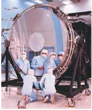
A satellite-dish antenna is a concave reflector for televi-sion signals from a satellite in orbit around the Earth. The signals are carried by microwaves that, because the satellite is so far away, are parallel when they arrive at the dish. These waves reflect from the dish and are focused on the receiver at the focal point of the dish.
Focal length
Mirror equation in terms of focal length
Courtesy of Thomson Consumer Electronics
Convex Mirrors
Figure 36.13 shows the formation of an image by a convex mirror—that is, one silvered so that light is reflected from the outer, convex surface. This is sometimes called a diverging mirrorbecause the rays from any point on an object diverge after reflection as though they were coming from some point behind the mirror. The image in Figure 36.13 is virtual because the reflected rays only appear to originate at the image point, as indicated by the dashed lines. Furthermore, the image is always upright and smaller than the object. This type of mirror is often used in stores to foil shoplifters. A single mirror can be used to survey a large field of view because it forms a smaller image of the interior of the store.
We do not derive any equations for convex spherical mirrors because we can use Equations 36.2, 36.4, and 36.6 for either concave or convex mirrors if we adhere to the following procedure. Let us refer to the region in which light rays move toward the mirror as the front side of the mirror, and the other side as the back side.For example, in Figures 36.11 and 36.13, the side to the left of the mirrors is the front side, and the side to the right of the mirrors is the back side. Figure 36.14 states the sign conventions for object and image distances, and Table 36.1 summarizes the sign conventions for all quantities.
Ray Diagrams for Mirrors
The positions and sizes of images formed by mirrors can be conveniently deter-mined with ray diagrams. These graphical constructions reveal the nature of the image and can be used to check results calculated from the mirror and magnifi ca-tion equaca-tions. To draw a ray diagram, we need to know the posica-tion of the object and the locations of the mirror’s focal point and center of curvature. We then draw three principal rays to locate the image, as shown by the examples in Figure 36.15.
Front
Back
O I F C
p q
Figure 36.13 Formation of an image by a spherical convex mirror. The image formed
by the real object is virtual and upright.
Front, or real, side
Reflected light
Back, or virtual, side
p and q negative
No light p and q positive
Incident light
Convex or concave mirror
Figure 36.14 Signs of pand qfor
convex and concave mirrors.
▲
PITFALL PREVENTION
36.3
Watch Your Signs
Success in working mirror problems (as well as problems involving refracting surfaces and thin lenses) is largely determined by proper sign choices when substituting into the equations. The best way to become adept at this is to work a multitude of problems on your own. Watching your instructor or reading the example problems is no substitute for practice.
Quantity Positive When Negative When
Object location (p) Object is in front of Object is in back
mirror (real object) of mirror (virtual object) Image location (q) Image is in front of Image is in back of
mirror (real image) mirror (virtual image) Image height (h!) Image is upright Image is inverted Focal length (f) Mirror is concave Mirror is convex
and radius (R)
Magnification (M) Image is upright Image is inverted Sign Conventions for Mirrors
S E C T I O N 3 6 . 2 • Images Formed by Spherical Mirrors 1135
(a) 1
2
3
C F
O
Front Back
I
Principal axis
(b) 1
2
3
C F O I
Front Back
(c) C F
O I
1
2
3
Front Back
Active Figure 36.15 Ray diagrams for spherical mirrors, along with corresponding
photographs of the images of candles. (a) When the object is located so that the center of curvature lies between the object and a concave mirror surface, the image is real, inverted, and reduced in size. (b) When the object is located between the focal point and a concave mirror surface, the image is virtual, upright, and enlarged. (c) When the object is in front of a convex mirror, the image is virtual, upright, and reduced in size.
Photos courtesy David Rogers
These rays all start from the same object point and are drawn as follows. We may choose any point on the object; here, we choose the top of the object for simplicity. For concave mirrors (see Figs. 36.15a and 36.15b), we draw the following three principal rays:
• Ray 1 is drawn from the top of the object parallel to the principal axis and is reflected through the focal point F.
• Ray 2 is drawn from the top of the object through the focal point and is reflected parallel to the principal axis.
• Ray 3 is drawn from the top of the object through the center of curvature Cand is reflected back on itself.
• Ray 1 is drawn from the top of the object parallel to the principal axis and is reflected away fromthe focal point F.
• Ray 2 is drawn from the top of the object toward the focal point on the back side of the mirror and is reflected parallel to the principal axis.
• Ray 3 is drawn from the top of the object toward the center of curvature Con the back side of the mirror and is reflected back on itself.
The intersection of any two of these rays locates the image. The third ray serves as a check of the construction. The image point obtained in this fashion must always agree with the value of qcalculated from the mirror equation. With concave mirrors, note what happens as the object is moved closer to the mirror. The real, inverted image in Figure 36.15a moves to the left as the object approaches the focal point. When the object is at the focal point, the image is infinitely far to the left. However, when the object lies between the focal point and the mirror surface, as shown in Figure 36.15b, the image is virtual, upright, and enlarged. This latter situation applies when you use a shaving mirror or a makeup mirror, both of which are concave. Your face is closer to the mirror than the focal point, and you see an upright, enlarged image of your face.
For convex mirrors (see Fig. 36.15c), we draw the following three principal rays:
Quick Quiz 36.3
You wish to reflect sunlight from a mirror onto some paper under a pile of wood in order to start a fire. Which would be the best choice for the type of mirror? (a) flat (b) concave (c) convex.Quick Quiz 36.4
Consider the image in the mirror in Figure 36.16. Based on the appearance of this image, you would conclude that (a) the mirror is concave and the image is real. (b) the mirror is concave and the image is virtual. (c) the mirror is convex and the image is real. (d) the mirror is convex and the image is virtual.Figure 36.16 (Quick Quiz 36.4)
What type of mirror is this?
In a convex mirror, the image of an object is always virtual, upright, and reduced in size as shown in Figure 36.15c. In this case, as the object distance decreases, the virtual image increases in size and moves away from the focal point toward the mirror as the object approaches the mirror. You should construct other diagrams to verify how image position varies with object position.
▲
PITFALL PREVENTION
36.4
We Are
Choosing
a
Small Number of
Rays
A hugenumber of light rays leave each point on an object (and pass through each point on an image). In a principal-ray dia-gram, which displays the charac-teristics of the image, we choose only a few rays that follow simply stated rules. Locating the image by calculation complements the diagram.
S E C T I O N 3 6 . 2 • Images Formed by Spherical Mirrors 1137
Example 36.4 The Image formed by a Concave Mirror
image. In this case, the mirror equation gives
The image is virtual because it is located behind the mirror, as expected. The magnification of the image is
The image is twice as large as the object, and the positive sign for Mindicates that the image is upright (see Fig. 36.15b).
What If? Suppose you set up the candle and mirror appara-tus illustrated in Figure 36.15a and described in part (A) of the example. While adjusting the apparatus, you accidentally strike the candle with your elbow so that it begins to slide toward the mirror at velocity vp. How fast does the image of the candle move?
Answer We solve the mirror equation, Equation 36.6, for q:
Differentiating this equation with respect to time gives us the velocity of the image vq"dq/dt:
For the object position of 25.0 cm in part (A), the velocity of the image is
Thus, the speed of the image is less than that of the object in this case.
We can see two interesting behaviors of this function for
vq. First, note that the velocity is negative regardless of the
value of p orf. Thus, if the object moves toward the mirror, the image moves toward the left in Figure 36.15 without regard for the side of the focal point at which the object is located or whether the mirror is concave or convex. Second, in the limit of p:0, the velocity vqapproaches $vp. As the object moves
very close to the mirror, the mirror looks like a plane mirror, the image is as far behind the mirror as the object is in front, and both the object and the image move with the same speed.
vq" $ Assume that a certain spherical mirror has a focal length of
&10.0 cm. Locate and describe the image for object distances of
(A) 25.0 cm,
(B) 10.0 cm, and
(C) 5.00 cm.
Solution Because the focal length is positive, we know that this is a concave mirror (see Table 36.1).
(A) This situation is analogous to that in Figure 36.15a; hence, we expect the image to be real. We find the image distance by using Equation 36.6:
The magnification of the image is given by Equation 36.2:
The fact that the absolute value of Mis less than unity tells us that the image is smaller than the object, and the negative sign for Mtells us that the image is inverted. Because qis positive, the image is located on the front side of the mirror and is real.
(B) When the object distance is 10.0 cm, the object is located at the focal point. Now we find that
which means that rays originating from an object positioned at the focal point of a mirror are reflected so that the image is formed at an infinite distance from the mirror; that is, the rays travel parallel to one another after reflection. This is the situa-tion in a flashlight, where the bulb filament is placed at the focal point of a reflector, producing a parallel beam of light.
(C) When the object is at p"5.00 cm, it lies halfway between the focal point and the mirror surface, as shown in Figure 36.15b. Thus, we expect a magnified, virtual, upright
'
Investigate the image formed for various object positions and mirror focal lengths at the Interactive Worked Example link athttp://www.pse6.com.
Interactive
Example 36.5 The Image from a Convex Mirror
(B) the magnification of the image.
Solution (A) This situation is depicted in Figure 36.15c. We should expect to find an upright, reduced, virtual image. To find the image position, we use Equation 36.6:
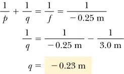
An anti-shoplifting mirror, as shown in Figure 36.17, shows an image of a woman who is located 3.0 m from the mirror. The focal length of the mirror is $0.25 m. Find
(A) the position of her image and
36.3
Images Formed by Refraction
In this section we describe how images are formed when light rays are refracted at the boundary between two transparent materials. Consider two transparent media having indices of refraction n1and n2, where the boundary between the two media is a spheri-cal surface of radius R(Fig. 36.18). We assume that the object at Ois in the medium for which the index of refraction is n1. Let us consider the paraxial rays leaving O. As we shall see, all such rays are refracted at the spherical surface and focus at a single point I, the image point.
Figure 36.19 shows a single ray leaving point Oand refracting to point I. Snell’s law of refraction applied to this ray gives
Because #1and #2are assumed to be small, we can use the small-angle approximation sin ###(with angles in radians) and say that
Now we use the fact that an exterior angle of any triangle equals the sum of the two opposite interior angles. Applying this rule to triangles OPC and PIC in Figure 36.19 gives
( " #2&) #1"% & ( n1#1"n2#2 n1 sin #1"n2 sin #2
The negative value of qindicates that her image is virtual, or behind the mirror, as shown in Figure 36.15c.
(B) The magnification of the image is
The image is much smaller than the woman, and it is upright because Mis positive.
&0.077
M" $q
p " $
$
$0.23 m 3.0 m
%
"$0.23 m
q"
1
q "
1
$0.25 m $ 1 3.0 m 1
p &
1
q "
1
f "
1
$0.25 m
Figure 36.17 (Example 36.5) Convex mirrors, often used
for security in department stores, provide wide-angle viewing.
Investigate the image formed for various object positions and mirror focal lengths at the Interactive Worked Example link athttp://www.pse6.com.
n1 < n2
O I
p q
n2
n1
R
Figure 36.18 An image formed by
refraction at a spherical surface. Rays making small angles with the principal axis diverge from a point object at Oand are refracted through the image point I.
©
If we combine all three expressions and eliminate #1and #2, we find that
(36.7)
From Figure 36.19, we see three right triangles that have a common vertical leg of length d. For paraxial rays (unlike the relatively large-angle ray shown in Fig. 36.19), the horizontal legs of these triangles are approximately pfor the triangle containing angle %, Rfor the triangle containing angle (, and qfor the triangle containing angle ). In the small-angle approximation, tan###, so we can write the approximate rela-tionships from these triangles as follows:
We substitute these expressions into Equation 36.7 and divide through by dto give
(36.8)
For a fixed object distance p, the image distance qis independent of the angle that the ray makes with the axis. This result tells us that all paraxial rays focus at the same point I. As with mirrors, we must use a sign convention if we are to apply this equation to a variety of cases. We define the side of the surface in which light rays originate as the front side. The other side is called the back side. Real images are formed by refraction in back of the surface, in contrast with mirrors, where real images are formed in front of the reflecting surface. Because of the difference in location of real images, the refraction sign conventions for q and Rare opposite the reflection sign conventions. For example, qand Rare both positive in Figure 36.19. The sign conventions for spher-ical refracting surfaces are summarized in Table 36.2.
We derived Equation 36.8 from an assumption that n1*n2in Figure 36.19. This assumption is not necessary, however. Equation 36.8 is valid regardless of which index of refraction is greater.
n1 p &
n2 q "
n2$n1 R tan %#%# d
p
tan (#(# d
R
tan )#)# d q n1% &n2) "(n2$n1)(
S E C T I O N 3 6 . 3 • Images Formed by Refraction 1139
Relation between object and image distance for a refracting surface
O
P
R
C
n1 n2
d
p q
γ
α β
I
θ1 θ2
Figure 36.19 Geometry used to derive Equation 36.8, assuming that n1*n2.
Quantity Positive When Negative When
Object location (p) Object is in front of Object is in back of surface (real object) surface (virtual object) Image location (q) Image is in back of Image is in front of
surface (real image) surface (virtual image) Image height (h!) Image is upright Image is inverted Radius (R) Center of curvature Center of curvature
is in back of surface is in front of surface Sign Conventions for Refracting Surfaces
Flat Refracting Surfaces
If a refracting surface is flat, then Ris infinite and Equation 36.8 reduces to
(36.9)
From this expression we see that the sign of qis opposite that of p. Thus, according to Table 36.2, the image formed by a flat refracting surface is on the same
side of the surface as the object. This is illustrated in Figure 36.20 for the
situation in which the object is in the medium of index n1and n1is greater than n2. In this case, a virtual image is formed between the object and the surface. If n1 is less than n2, the rays in the back side diverge from each other at lesser angles than those in Figure 36.20. As a result, the virtual image is formed to the left of the object.
q" $n2 n1
p n1
p " $ n2
q
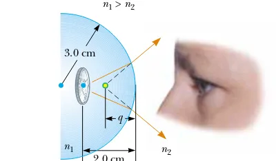
Example 36.7 Gaze into the Crystal Ball
Solution Because n1+n2, where n2"1.00 is the index of
refraction for air, the rays originating from the coin are refracted away from the normal at the surface and diverge outward. Hence, the image is formed inside the paper-weight and is virtual. Applying Equation 36.8 and noting A set of coins is embedded in a spherical plastic
paper-weight having a radius of 3.0 cm. The index of refraction of the plastic is n1"1.50. One coin is located 2.0 cm from the
edge of the sphere (Fig. 36.21). Find the position of the image of the coin.
O
I
q
p
n1 > n2
n1 n2
Active Figure 36.20 The image
formed by a flat refracting surface is virtual and on the same side of the surface as the object. All rays are assumed to be paraxial.
At the Active Figures link at http://www.pse6.com, you can move the object to see the effect on the location of the
image.
Quick Quiz 36.5
In Figure 36.18, what happens to the image point Ias theobject point Ois moved to the right from very far away to very close to the refracting surface? (a) It is always to the right of the surface. (b) It is always to the left of the surface. (c) It starts off to the left and at some position of O, Imoves to the right of the surface. (d) It starts off to the right and at some position of O, Imoves to the left of the surface.
Quick Quiz 36.6
In Figure 36.20, what happens to the image point Ias the object point Omoves toward the right-hand surface of the material of index of refraction n1? (a) It always remains between O and the surface, arriving at thesurface just as Odoes. (b) It moves toward the surface more slowly than O so that eventually Opasses I. (c) It approaches the surface and then moves to the right of the surface.
Conceptual Example 36.6 Let’s Go Scuba Diving!
when a person under water views objects with the naked eye. In this case, light rays from an object focus behind the retina, resulting in a blurred image. When a mask is used, the air space between the eye and the mask surface provides the normal amount of refraction at the eye–air interface, and the light from the object focuses on the retina.
It is well known that objects viewed under water with the naked eye appear blurred and out of focus. However, a scuba diver using a mask has a clear view of underwater objects. Explain how this works, using the facts that the indices of refraction of the cornea, water, and air are 1.376, 1.333, and 1.00029, respectively.
36.4
Thin Lenses
Lenses are commonly used to form images by refraction in optical instruments, such as cameras, telescopes, and microscopes. We can use what we just learned about images formed by refracting surfaces to help us locate the image formed by a lens. We recognize that light passing through a lens experiences refraction at two
Figure 36.21 (Example 36.7) Light rays from a coin embedded
in a plastic sphere form a virtual image between the surface of the object and the sphere surface. Because the object is inside the sphere, the front of the refracting surface is the interiorof the sphere.
from Table 36.2 that Ris negative, we obtain
The negative sign for qindicates that the image is in front of the surface—in other words, in the same medium as the object, as shown in Figure 36.21. Being in the same medium as the object, the image must be virtual. (See Table 36.2.)
Example 36.8 The One That Got Away
The apparent height h!of the fish is pond (Fig. 36.22). What is the apparent depth of the fish, as viewed from directly overhead?
Solution Because the refracting surface is flat, Ris infinite. Hence, we can use Equation 36.9 to determine the location of the image with p"d. Using the indices of refraction given in Figure 36.22, we obtain
Because q is negative, the image is virtual, as indicated by
Figure 36.22 (Example 36.8) The apparent depth qof the
formed by one refracting surface serves as the object for the second surface. We shall analyze a thick lens first and then let the thickness of the lens be approxi-mately zero.
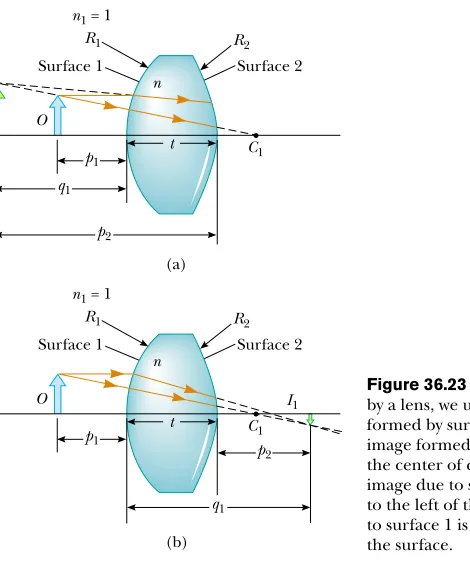
Consider a lens having an index of refraction n and two spherical surfaces with radii of curvature R1and R2, as in Figure 36.23. (Note that R1is the radius of curva-ture of the lens surface that the light from the object reaches first and that R2is the radius of curvature of the other surface of the lens.) An object is placed at point Oat a distance p1in front of surface 1.
Let us begin with the image formed by surface 1. Using Equation 36.8 and assum-ing that n1"1 because the lens is surrounded by air, we find that the image I1formed by surface 1 satisfies the equation
(36.10)
where q1 is the position of the image due to surface 1. If the image due to surface 1 is virtual (Fig. 36.23a), q1is negative, and it is positive if the image is real (Fig. 36.23b).
Now we apply Equation 36.8 to surface 2, taking n1"nand n2"1. (We make this switch in index because the light rays approaching surface 2 are in the material of the lens,and this material has index n.) Taking p2as the object distance for surface 2 and q2as the image distance gives
(36.11)
We now introduce mathematically the fact that the image formed by the first surface acts as the object for the second surface. We do this by noting from Figure 36.23 that p2, measured from surface 2, is related to q1as follows:
Virtual image from surface 1 (Fig. 36.23a): p2" $q1&t (q1is negative) Real image from surface 1 (Fig. 36.23b): p2" $q1&t (q1is positive)
n p2
& 1 q2
" 1$n R2 1
p1 & n
q1
" n$1 R1 t
p1
q1
p2
O I1
C1
Surface 1 R1
n
Surface 2 R2
n1 = 1
t p1
q1
O
C1
Surface 1 R1
n
Surface 2 R2
n1 = 1
p2
I1
(a)
(b)
Figure 36.23 To locate the image formed
by a lens, we use the virtual image at I1
formed by surface 1 as the object for the image formed by surface 2. The point C1is
the center of curvature of surface 1. (a) The image due to surface 1 is virtual so that I1is
to the left of the surface. (b) The image due to surface 1 is real so that I1is to the right of
where t is the thickness of the lens. For a thin lens (one whose thickness is small compared to the radii of curvature), we can neglect t. In this approximation, we see that p2" $q1for either type of image from surface 1. (If the image from surface 1 is real, the image acts as a virtual object, so p2is negative.) Hence, Equation 36.11 becomes
(36.12)
Adding Equations 36.10 and 36.12, we find that
(36.13)
For a thin lens, we can omit the subscripts on p1and q2in Equation 36.13 and call the object distance p and the image distance q, as in Figure 36.24. Hence, we can write Equation 36.13 in the form
(36.14)
This expression relates the image distance qof the image formed by a thin lens to the object distance pand to the lens properties (index of refraction and radii of curva-ture). It is valid only for paraxial rays and only when the lens thickness is much less than R1and R2.
The focal lengthfof a thin lens is the image distance that corresponds to an infi
-nite object distance, just as with mirrors. Letting p approach 'and q approach fin Equation 36.14, we see that the inverse of the focal length for a thin lens is
(36.15)
This relationship is called the lens makers’ equationbecause it can be used to deter-mine the values of R1and R2that are needed for a given index of refraction and a desired focal length f. Conversely, if the index of refraction and the radii of curvature of a lens are given, this equation enables a calculation of the focal length. If the lens is immersed in something other than air, this same equation can be used, with n inter-preted as the ratio of the index of refraction of the lens material to that of the sur-rounding fluid.
Using Equation 36.15, we can write Equation 36.14 in a form identical to Equation 36.6 for mirrors:
(36.16) 1
p & 1 q "
1 f 1
f "(n$1)
$
1 R1$ 1
R2
%
1p & 1
q "(n$1)
$
1 R1$ 1
R2
%
1p1 & 1
q2
"(n$1)
$
1 R1$ 1
R2
%
$ nq1 & 1
q2
" 1$n R2
S E C T I O N 3 6 . 4 • Thin Lenses 1143
C1
C2
O
p q
I R2
R1
Figure 36.24 Simplified geometry for a thin lens.
Lens makers’ equation
f f
f f
(a)
(b)
F1 F2
F1 F2
F1 F2
F1 F2
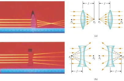
Figure 36.25 (Left) Effects of a converging lens (top) and a diverging lens (bottom)
on parallel rays. (Right) Parallel light rays pass through (a) a converging lens and (b) a diverging lens. The focal length is the same for light rays passing through a given lens in either direction. Both focal points F1and F2are the same distance from the lens.
Henry Leap and Jim Lehman
Front
p positive q negative
Incident light
Back
p negative q positive
Refracted light
Figure 36.26 A diagram for
obtaining the signs of pand qfor a thin lens. (This diagram also applies to a refracting surface.)
Quantity Positive When Negative When
Object location (p) Object is in front of Object is in back of lens (real object) lens (virtual object) Image location (q) Image is in back of Image is in front of
lens (real image) lens (virtual image) Image height (h!) Image is upright Image is inverted R1and R2 Center of curvature Center of curvature
is in back of lens is in front of lens Focal length (f) Converging lens Diverging lens Sign Conventions for Thin Lenses
Table 36.3
This equation, called the thin lens equation,can be used to relate the image distance and object distance for a thin lens.
Because light can travel in either direction through a lens, each lens has two focal points, one for light rays passing through in one direction and one for rays passing through in the other direction. This is illustrated in Figure 36.25 for a biconvex lens (two convex surfaces, resulting in a converging lens) and a biconcave lens (two con-cave surfaces, resulting in a diverging lens).
Figure 36.26 is useful for obtaining the signs of pand q, and Table 36.3 gives the sign conventions for thin lenses. Note that these sign conventions are the same as those for refracting surfaces (see Table 36.2). Applying these rules to a biconvex lens, we see that when p+f, the quantities p, q, and R1are positive, and R2 is negative. Therefore, p, q, and fare all positive when a converging lens forms a real image of an object. For a biconcave lens, pand R2are positive and qand R1are negative, with the result that fis negative.
▲
PITFALL PREVENTION
36.5
A Lens Has Two
Focal Points but
Only One Focal
Length
A lens has a focal point on each side, front and back. However, there is only one focal length— each of the two focal points is located the same distance from the lens (Fig, 36.25). This can be seen mathematically by inter-changing R1 and R2 in Equation
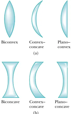
Various lens shapes are shown in Figure 36.27. Note that a converging lens is thicker at the center than at the edge, whereas a diverging lens is thinner at the center than at the edge.
Magnification of Images
Consider a thin lens through which light rays from an object pass. As with mirrors (Eq. 36.2), we could analyze a geometric construction to show that the lateral magnification of the image is
From this expression, it follows that when Mis positive, the image is upright and on the same side of the lens as the object. When Mis negative, the image is inverted and on the side of the lens opposite the object.
Ray Diagrams for Thin Lenses
Ray diagrams are convenient for locating the images formed by thin lenses or systems of lenses. They also help clarify our sign conventions. Figure 36.28 shows such dia-grams for three single-lens situations.
To locate the image of a converginglens (Fig. 36.28a and b), the following three rays are drawn from the top of the object:
M" h!
(a) Converging lenses have a posi-tive focal length and are thickest at the middle. (b) Diverging lenses have a negative focal length and are thickest at the edges.
Active Figure 36.28 Ray diagrams for locating the image formed
by a thin lens. (a) When the object is in front of and outside the focal point of a converging lens, the image is real, inverted, and on the back side of the lens. (b) When the object is between the focal point and a converging lens, the image is virtual, upright, larger than the object, and on the front side of the lens. (c) When an object is anywhere in front of a diverging lens, the image is virtual, upright, smaller than the object, and on the front side of the lens.
At the Active Figures link at http://www.pse6.com, you can move the objects and change the focal length of the lenses to see the effect on the images.
• Ray 1 is drawn parallel to the principal axis. After being refracted by the lens, this ray passes through the focal point on the back side of the lens.
• Ray 2 is drawn through the center of the lens and continues in a straight line.
To locate the image of a diverging lens (Fig. 36.28c), the following three rays are drawn from the top of the object:
• Ray 1 is drawn parallel to the principal axis. After being refracted by the lens, this ray emerges directed away from the focal point on the front side of the lens.
• Ray 2 is drawn through the center of the lens and continues in a straight line.
• Ray 3 is drawn in the direction toward the focal point on the back side of the lens and emerges from the lens parallel to the principal axis.
For the converging lens in Figure 36.28a, where the object is to the left of the focal point (p+f), the image is real and inverted. When the object is between the focal point and the lens (p*f), as in Figure 36.28b, the image is virtual and upright. For a diverging lens (see Fig. 36.28c), the image is always virtual and upright, regardless of where the object is placed. These geometric constructions are reasonably accurate only if the distance between the rays and the principal axis is much less than the radii of the lens surfaces.
Note that refraction occurs only at the surfaces of the lens. A certain lens design takes advantage of this fact to produce the Fresnel lens, a powerful lens without great thickness. Because only the surface curvature is important in the refracting qualities of the lens, material in the middle of a Fresnel lens is removed, as shown in the cross sections of lenses in Figure 36.29. Because the edges of the curved segments cause some distortion, Fresnel lenses are usually used only in situations in which image quality is less important than reduction of weight. A classroom overhead projector often uses a Fresnel lens; the circular edges between segments of the lens can be seen by looking closely at the light projected onto a screen.
Figure 36.29 The Fresnel lens on
the left has the same focal length as the thick lens on the right but is made of much less glass.
Quick Quiz 36.7
What is the focal length of a pane of window glass? (a) zero (b) infinity (c) the thickness of the glass (d) impossible to determineQuick Quiz 36.8
Diving masks often have a lens built into the glass for divers who do not have perfect vision. This allows the individual to dive without the necessity for glasses, because the lenses in the faceplate perform the necessary refraction to provide clear vision. The proper design allows the diver to see clearly with the mask on bothunder water and in the open air. Normal eyeglasses have lenses that are curved on both the front and back surfaces. The lenses in a diving mask should be curved (a) only on the front surface (b) only on the back surface (c) on both the front and back surfaces.Example 36.9 Images Formed by a Converging Lens
Solution
(A) First we construct a ray diagram as shown in Figure 36.30a. The diagram shows that we should expect a real, inverted, smaller image to be formed on the back side of the lens. The thin lens equation, Equation 36.16, can be used to find the image distance:
1
p &
1
q "
1
f
A converging lens of focal length 10.0 cm forms images of objects placed
(A) 30.0 cm,
(B) 10.0 cm, and
(C) 5.00 cm from the lens.
In each case, construct a ray diagram, find the image distance and describe the image.
S E C T I O N 3 6 . 4 • Thin Lenses 1147
The positive sign for the image distance tells us that the image is indeed real and on the back side of the lens. The magnification of the image is
Thus, the image is reduced in height by one half, and the negative sign for Mtells us that the image is inverted.
(B) No calculation is necessary for this case because we know that, when the object is placed at the focal point, the image is formed at infinity. This is readily verified by substituting p"10.0 cm into the thin lens equation.
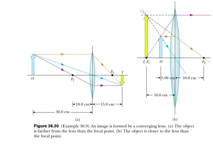
(C) We now move inside the focal point. The ray diagram in Figure 36.30b shows that in this case the lens acts as a magnifying glass; that is, the image is magnified, upright, on the same side of the lens as the object, and virtual. Because the object distance is 5.00 cm, the thin lens equa-tion gives
and the magnification of the image is
The negative image distance tells us that the image is virtual and formed on the side of the lens from which the light is incident, the front side. The image is enlarged, and the posi-tive sign for Mtells us that the image is upright.
What If? What if the object moves right up to the lens surface, so thatpB0? Where is the image?
Answer In this case, because p**R, where Ris either of the radii of the surfaces of the lens, the curvature of the lens can be ignored and it should appear to have the same effect as a plane piece of material. This would suggest that the image is just on the front side of the lens, at q"0. We can verify this mathematically by rearranging the thin lens equation:
If we let p:0, the second term on the right becomes very large compared to the first and we can neglect 1/f. The equation becomes
Thus, qis on the front side of the lens (because it has the opposite sign as p), and just at the lens surface.
q" $p"0
Figure 36.30 (Example 36.9) An image is formed by a converging lens. (a) The object
is farther from the lens than the focal point. (b) The object is closer to the lens than the focal point.
Investigate the image formed for various object positions and lens focal lengths at the Interactive Worked Example link at
Example 36.10 The Case of a Diverging Lens
This result confirms that the image is virtual, smaller than the object, and upright.
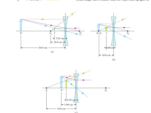
(B) When the object is at the focal point, the ray diagram appears as in Figure 36.31b. In the thin lens equation, using
p"10.0 cm, we have
The magnification of the image is
Notice the difference between this situation and that for a converging lens. For a diverging lens, an object at the focal point does not produce an image infinitely far away.
(C) When the object is inside the focal point, at p"5.00 cm, the ray diagram in Figure 36.31c shows that we expect a virtual image that is smaller than the object and upright. In
&0.500
M" $q
p " $
$
$5.00 cm 10.0 cm
%
"$5.00 cm
q"
1 10.0 cm &
1
q "
1
$10.0 cm Repeat Example 36.9 for a diverging lens of focal length
10.0 cm.
Solution
(A) We begin by constructing a ray diagram as in Figure 36.31a taking the object distance to be 30.0 cm. The dia-gram shows that we should expect an image that is virtual, smaller than the object, and upright. Let us now apply the thin lens equation with p"30.0 cm:
The magnification of the image is
&0.250
M" $q
p " $
$
$7.50 cm 30.0 cm
%
"$7.50 cm
q"
1 30.0 cm &
1
q "
1
$10.0 cm 1
p &
1
q "
1
f
I O
(c) F1
5.00 cm 3.33 cm
10.0 cm
F2
I O
(a) F1
30.0 cm
10.0 cm 7.50 cm
F2 O, F1 I
(b) 5.00 cm
10.0 cm
F2
Figure 36.31 (Example 36.10) An image is formed by a diverging lens. (a) The object
is farther from the lens than the focal point. (b) The object is at the focal point. (c) The object is closer to the lens than the focal point.
Combination of Thin Lenses
If two thin lenses are used to form an image, the system can be treated in the following manner. First, the image formed by the first lens is located as if the second lens were not present. Then a ray diagram is drawn for the second lens, with the image formed by the first lens now serving as the object for the second lens. The second image formed is the final image of the system. If the image formed by the first lens lies on the back side of the second lens, then that image is treated as a virtual objectfor the second lens (that is, in the thin lens equation, pis negative). The same procedure can be extended to a system of three or more lenses. Because the magnification due to the second lens is performed on the magnified image due to the first lens, the overall magnification of the image due to the combination of lenses is the product of the individual magnifications.
Let us consider the special case of a system of two lenses of focal lengths f1and f2 in contact with each other. If p1"pis the object distance for the combination, applica-tion of the thin lens equaapplica-tion (Eq. 36.16) to the first lens gives
1 p &
1 q1
" 1 f1
S E C T I O N 3 6 . 4 • Thin Lenses 1149
this case, the thin lens equation gives
$3.33 cm
q"
1 5.00 cm &
1
q "
1
$10.0 cm
and the magnification of the image is
This confirms that the image is virtual, smaller than the object, and upright.
&0.667
M" $
$
$3.33 cm5.00 cm
%
"Example 36.11 A Lens Under Water
equation by the second gives
Because fair"40.0 cm, we find that
fwater"3.71fair"3.71(40.0 cm)"
The focal length of any lens is increased by a factor (n$1)/(n! $1) when the lens is immersed in a fluid, where n!is the ratio of the index of refraction nof the lens material to that of the fluid.
148 cm
fwater
fair
" n$1
n! $1 "
1.52$1 1.14$1 "3.71 A converging glass lens (n"1.52) has a focal length of
40.0 cm in air. Find its focal length when it is immersed in water, which has an index of refraction of 1.33.
Solution We can use the lens makers’ equation (Eq. 36.15) in both cases, noting that R1and R2remain the same in air
and water:
where n! is the ratio of the index of refraction of glass to that of water: n! "1.52/1.33"1.14. Dividing the first
1
fwater
"(n! $1)
$
1R1 $ 1
R2
%
1
fair
"(n$1)
$
1R1 $ 1
R2
%
Investigate the image formed for various object positions and lens focal lengths at the Interactive Worked Example link at
http://www.pse6.com.
Light from a distant object is brought into focus by two converging lenses.
where q1is the image distance for the first lens. Treating this image as the object for the second lens, we see that the object distance for the second lens must be p2" $q1. (The distances are the same because the lenses are in contact and assumed to be infi ni-tesimally thin. The object distance is negative because the object is virtual.) Therefore, for the second lens,
where q"q2is the final image distance from the second lens, which is the image distance for the combination. Adding the equations for the two lenses eliminates q1and gives
If we consider replacing the combination with a single lens that will form an image at the same location, we see that its focal length is related to the individual focal lengths by
(36.17)
Therefore, two thin lenses in contact with each other are equivalent to a single thin lens having a focal length given by Equation 36.17.
1 of two thin lenses in contact
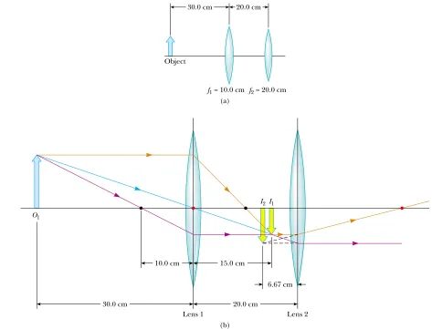
Example 36.12 Where Is the Final Image?
The magnification of this image is
The image formed by this lens acts as the object for the second lens. Thus, the object distance for the second lens is 20.0 cm$15.0 cm"5.00 cm. We again apply the thin lens equation to find the location of the final image:
The magnification of the second image is
Thus, the overall magnification of the system is
To finalize the problem, note that the negative sign on the overall magnification indicates that the final image is inverted with respect to the initial object. The fact that the absolute value of the magnification is less than one tells us that the final image is smaller than the object. The fact that
q2is negative tells us that the final image is on the front, or
left, side of lens 2. All of these conclusions are consistent with the ray diagram in Figure 36.32b.
$0.667
and f2"20.0 cm are separated by 20.0 cm, as illustrated in
Figure 36.32a. An object is placed 30.0 cm to the left of lens 1. Find the position and the magnification of the final image.
Solution Conceptualize by imagining light rays passing through the first lens and forming a real image (because
p +f) in the absence of the second lens. Figure 36.32b shows these light rays forming the inverted image I1. Once
the light rays converge to the image point, they do not stop. They continue through the image point and interact with the second lens. The rays leaving the image point behave in the same way as the rays leaving an object. Thus, the image of the first lens serves as the object of the second lens. We categorize this problem as one in which we apply the thin lens equation, but in stepwise fashion to the two lenses.
S E C T I O N 3 6 . 4 • Thin Lenses 1151
30.0 cm 20.0 cm
Object
f1 = 10.0 cm f2 = 20.0 cm
(a)
(b)
I2I1
Lens 1 Lens 2
20.0 cm
6.67 cm 15.0 cm
10.0 cm O1
30.0 cm
What If? Suppose we want to create an upright image with this system of two lenses. How must the second lens be moved in order to achieve this?
Answer Because the object is farther from the first lens than the focal length of that lens, we know that the first image is inverted. Consequently, we need the second lens to
invert the image once again so that the final image is upright. An inverted image is only formed by a converging lens if the object is outside the focal point. Thus, the image due to the first lens must be to the left of the focal point of the second lens in Figure 36.32b. To make this happen, we must move the second lens at least as far away from the first lens as the sum q1&f2"15.0 cm&20.0 cm"35.0 cm.
Figure 36.32 (Example 36.12) (a) A combination of two converging lenses. (b) The
ray diagram showing the location of the final image due to the combination of lenses. The black dots are the focal points of lens 1 while the red dots are the focal points of lens 2.
Investigate the image formed by a combination of two lenses at the Interactive Worked Example link at http://www.pse6.com. Conceptual Example 36.13 Watch Your p’s and q’s!
related according to the same equation—the thin lens equation.
The curve in the upper right portion of the f" &10 cm graph corresponds to an object located on the front side of a lens, which we have drawn as the left side of the lens in our previous diagrams. When the object is at positive infinity, a real image forms at the focal point on the back side (the posi-tive side) of the lens, q"f. (The incoming rays are parallel in this case.) As the object moves closer to the lens, the image Use a spreadsheet or a similar tool to create two graphs of
image distance as a function of object distance—one for a lens for which the focal length is 10 cm and one for a lens for which the focal length is $10 cm.
36.5
Lens Aberrations
Our analysis of mirrors and lenses assumes that rays make small angles with the princi-pal axis and that the lenses are thin. In this simple model, all rays leaving a point source focus at a single point, producing a sharp image. Clearly, this is not always true. When the approximations used in this analysis do not hold, imperfect images are formed.
A precise analysis of image formation requires tracing each ray, using Snell’s law at each refracting surface and the law of reflection at each reflecting surface. This proce-dure shows that the rays from a point object do not focus at a single point, with the result that the image is blurred. The departures of actual images from the ideal pre-dicted by our simplified model are called aberrations.
Spherical Aberrations
Spherical aberrations occur because the focal points of rays far from the principal axis of a spherical lens (or mirror) are different from the focal points of rays of the same wavelength passing near the axis. Figure 36.34 illustrates spherical aberration for parallel rays passing through a converging lens. Rays passing through points near the center of
Figure 36.33 (Conceptual Example 36.13) (a) Image position as a function of object
position for a lens having a focal length of &10 cm. (b) Image position as a function of object position for a lens having a focal length of $10 cm.
moves farther from the lens, corresponding to the upward path of the curve. This continues until the object is located at the focal point on the near side of the lens. At this point, the rays leaving the lens are parallel, making the image infinitely far away. This is described in the graph by the asymptotic is now a virtual object, so it must have been formed by some other lens. For all locations of the virtual object, the image
distance is positive and less than the focal length. The final image is real, and its position approaches the focal point as
pbecomes more and more negative.
The f" $10 cm graph shows that a distant real object forms an image at the focal point on the front side of the lens. As the object approaches the lens, the image remains virtual and moves closer to the lens. But as we continue toward the left end of the paxis, the object becomes virtual. As the position of this virtual object approaches the focal