CONSERVATION OF STONE CLADDING ON THE FAÇADE
OF ROYAL PALACE IN CASERTA
I. Titomanlio a
a
Department of Architecture and Industrial Design, Second University of Naples, Aversa (CE), Italy
ingrid.titomanlio @unina2.itKEY WORDS: Royal Palace in Caserta, stones cladding, façade, cultural heritage, non – structural elements, seismic risk
ABSTRACT:
The beauty of cultural heritage and monumental architecture, is often linked to their non-structural elements and decorative stones façades cladding. The collapse of these elements causes significant consequences that interest the social, the economic, the historical and the technical fields. Several regulatory documents and literature studies contain methods to address the question of relief and of the risk analysis and due to the non – structural stones security. Among the references are widespread international regulatory documents prepared by the Federal Emergency Management Agency of the United States by Applied Technology Council and California. In Italy there are some indications contained in the Norme Tecniche per le Costruzioni and the Direttiva del Presidente
del Consiglio dei Ministri in 2007, finalize to the reduction of seismic risk assessment of cultural heritage. The paper, using
normative references and scientific researches, allows to analyze on Royal Palace of Caserta the safety and the preservation of cultural heritage and the vulnerability of non-structural stones façade cladding. Using sophisticated equipments of Laboratory ARS of the Second University of Naples, it was possible to analyze the collapse of stone elements due to degradation caused by natural phenomena of deterioration (age of the building, type of materials, geometries , mode of fixing of the elements themselves). The paper explains the collapse mechanisms of stones façade cladding of Luigi Vanvitelli Palace.
1. INTRODUCTION
1.1 History of the Royal Palace in Caserta
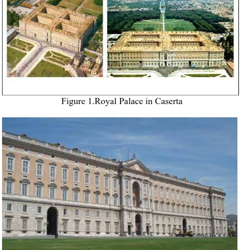
"One of the planimetric creations more harmonics, more logical, more perfect architecture of all times", so it was called the Royal Palace of Caserta by Gino Clerici in 1930 (Figure 1). The Royal Palace of Caserta, declared World Heritage by UNESCO, was wanted by the Bourbon kings of Naples as the seat of the representative government that had as capital. The Naples Royal Palace, surrounded by a large park, was also erected to cope with the appeared, at that time, one of the most prestigious royal residences: the Palace of Versailles. The architect Luigi Vanvitelli, already engaged in the restoration of the Basilica of Loreto on behalf of the Papal States, responded to the King call, convinced that the artist had the right idea to be able to express the grandeur and power of the Bourbon State. In addiction to the palace and park design, it was asked to Vanvitelli to decide about the accommodation surrounding urban area with the procurement of a new aqueduct (hereinafter referred Carolino). Charles III of Bourbon wanted to connect with a wide avenue the capital of the kingdom, precisely Naples, Caserta and the new structure, which was not completed, however, compared to what was expected (the large central dome and the four corner towers). Vanvitelli in Caserta came in 1751 and the following year, with a big ceremony, the final design was approved by the affixing of the first stone. This moment was painted under the canopy of the Throne Room by Gennaro Maldarelli. The commitment to the construction of the work required to Vanvitelli tiling of several collaborators: Marcello Fronton who followed him in the work of the building and Francesco Collecini for the park and the aqueduct. The work lasted a total of several years and some details were left unfinished. The kings who succeeded Charles III (Ferdinand
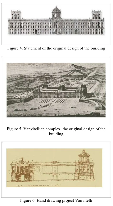
IV, who later became Ferdinand I) did not share the same enthusiasm for the construction of the Palace (Figure 2). When in 1773, Vanvitelli died, his son Carlo had to continue the completion of the work, but the genius of the father was difficult to interpret, so that it was difficult to do the work according to the original project (Figures 3 and 4).
Figure 1.Royal Palace in Caserta
Figure 2. Façade of the Royal Palace in Caserta
1.2 The Royal Palace and its materials
The palace covers an area of about 44,000 square meters (Figure 5). The materials needed in the construction of the work, which cost 6,133,507 ducats, were drawn largely from existing quarries in the area or in the territories of the kingdom: San Nicola la Strada (tuff), Bellona (travertine), Mondragone (gray marble), San Leucio (lime), Bacoli (pozzolan), Gaeta (arena), Capua (bricks and the like), Sicily, Calabria and Puglia, for different marbles. It was also used for the statues and some moldings, the white Carrara marble. The choice of marble necessary to the building was operated by the French sculptor Giuseppe Canart, restorer at the service of the king and connoisseur of ancient marbles. The plan of the building, rectangular in size 247 x 190 meters, with the interior divided into four courtyards (each of 3,800 sq m) by means of two buildings intersecting at right angles, can be defined as optimal model of architecture, responding to distribution requirements of the space according to the functions. Inspired by Berne's perspective is the setting of the two semicircles that develop before the Royal Palace and collect the whole vision of the long facade. Latter, performed in the travertine of St. Iorio and part brick, is spread over a scheme consisting in horizontal base and majestic composite order which acts as a closure at the top, a penthouse punctuated by small windows and shaded by a frame surmounted by a balustrade. The two corners and in the central part of the facade advances slightly for short sections highlighting the main entrance and the two ends of the building. The arc motion of the central door is repeated at the top, with a niche between open windows with semi - circular or triangular pediments and pairs of fluted columns that hold up the majestic pediment gable. The building extends for a total height of 41 meters, has 1,200 rooms lit by windows in 1742 of which 241 well open at the front and the same on the back (Figure 6). The chimneys on the roof in 1026, indicating the presence of fireplaces in almost every room. Different types of times (cruising, sailing, hip, barrel, basin, bowl-shaped, etc..) Covering the rooms of the Palace. This made it necessary to build the outer walls, which form the case of the building, with a thickness of 3.50 m on the ground floor. The roof of the building is a gable roof with a constant height, whose wooden roof timbers are abetone Sila. Each element is composed of two struts reinforced, three monks and a tie rod. These trusses are interspersed with those of mixed masonry and timber, in this way, the roof is supported by 76 elements dl first type and 64 of the second.
Figure 3. Part of the longitudinal section of the original design of the royal palace
The roof is formed with large tiles and channels coming from the furnaces of Portsmouth, as well as the bricks for the floors, put in place by talented teachers Zappi and Rossi. Immediately after the central gate with a superb gallery with three naves
(high and wide the median, narrower and lower the side), leads central octagon where bundles of stone columns Bigliemi (Sicily) hold strong steps to creating four large arches courtyards and - on the right - the majestic staircase decorated with polychrome marbles, 18.50 meters wide, 14.50 meters high and has 117 steps. Besides the octagon gallery continues its journey until it was lost in the green park with a view of the beautiful scenic movement.
Figure 4. Statement of the original design of the building
Figure 5. Vanvitellian complex: the original design of the building
Figure 6. Hand drawing project Vanvitelli
2. NON DESTRUCTIVE TESTING TO KNOW MASONRY BUILDINGS
2.1 Non - destructive testing
To test on masonry buildings (Figure 7), to achieve an adequate knowledge in terms of masonry mechanical integrity and material parameters. It should be done without damaging the building.
Non - destructive approaches must not damage and disrupt the materials being evaluated and this is particularly relevant for historic preservation purposes, where the value of historic materials can not be compromised. Nearly unheard of prior to the mid-1980s, masonry evaluation by non-destructive and in situ methods is now quite commonplace, with standardized test methods developed for many of the techniques.
The basis for many non-destructive testing (NDT) procedures arises from the medical, aerospace, and geophysical fields, adapted for the varying conditions widely that may be present in masonry buildings. The tests available for testing masonry structures range from the completely non-destructive, where there is no damage to the structure, through those where the masonry is slightly damaged, to partially destructive tests, tests: such as core, where the surface has to be repaired after the test (Figure 8).
Figure 7 . Courtyard of Royal Palace in Caserta
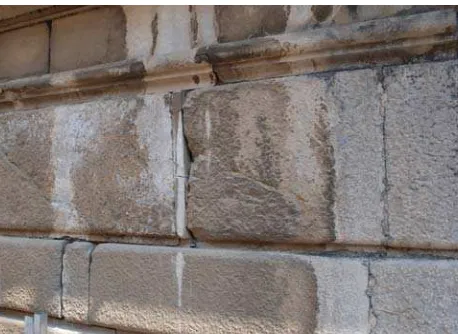
Figure 8. Stones on Façade of Royal Palace in Caserta
The range of properties that can be assessed using non-destructive tests and partially non-destructive tests is quite large and includes such fundamental parameters as elastic modulus and strength. It is also possible to check the quality of workmanship and structural integrity detecting voids and cracking as well as it is feasible to identify tie bars and reinforcement location. Non-destructive testing can be applied to both old and new structures. For new structures, the main applications are likely to be for quality control of materials or construction. The testing of existing structures is usually related to the building knowledge.
2.2 Pacometer
The pacometrica survey is a procedure of non-destructive analysis which allows the detection and measurement of the size of metallic elements and of the relative coating.
The Covermeter used is a Covermaster CM9, the Protovale Ltd. (Oxford). Unlike most of the similar tools, that use the principle of magnetic induction, the CM9 is based on the operational
principle theory of eddy current (eddy current) retaining all the advantages of stability (there are interference electrical, magnetic, thermal and there are no constraints due to the effects of ionic material moisture investigated), precision and repeatability (Figure 9).
Figure 9. Covermeter high precision digital COVERMASTER Elcometer P331-
H
2.3 Ground probing radar
The word GPR or G.P.R. (Ground Probing Radar), identifies radar equipment dedicated to the investigation of the subsoil, masonry structures and artifacts in general.
The GPR, in applications to the constructions, it is, in general, a technique that allows to disclose destructively and non-invasively the presence and location of anomalies or submerged objects using the phenomenon of reflection of electromagnetic waves.
In recent years the use of GPR techniques has had a growing trend. It is seen a considerable increase in interest in this geophysical technique dependent in large part by the economy of costs and execution time, as well as from the non-destructive investigation, even if the reading of the data presented, sometimes, some difficulties (Figure 10).
Figure 10. Principles of Operation of the G.P.R.
2.4 Endoscope
Endoscopic examination allows a visual examination of the internal cavity or the interior of small diameter holes made in specific parts of the construction. The operation is based on the properties of optical fibers to transmit light by means of successive reflections. Endoscopes, in fact, incorporate fiber optics and a light source to illuminate the internal cavity under consideration, they have also a graduated scale in the viewfinder that helps in the identification and estimation of the size of the observed objects. The returned image is reconstructed with the aid of a computer system, and the main results are presented as images to process and interpret. For the investigation has been used a flexible endoscope (fiberscope) PXL series XL PRO which has the particularity of being able to adapt to the change in linearity of the hole, allowing
investigations in holes or cavities of at least 10 mm wide. The program uses a patented system of control of the camera using a joystick and articulation All-Way ™ that allow easy positioning and re-orientation of the probe with a diameter of 3.9 mm. The fiberscope has a high resolution color camera (440000 pixels) (Figure11).
Figure 11. PXL Series - XL PRO Base System of Benecon S.C.aR.L
2.5 Thermocam
The infrared thermographic technique provides a visible representation of infrared energy radiated by an object, according to the fundamental law of Planck that all objects at temperatures above absolute zero emits infrared radiation. The scan cameras with infrared is a genuine approach 'global', allowing a rapid assessment of large regions without requiring direct access to the wall. In terms of heat flow, temperature differences surface are always present in the vicinity of materials with different density, capacity and / or thermal conductivity; these variations of the surface temperature are measured with special cameras sensitive to infrared in the range of 0.76 - 30 millimeters.
The range of sensitivity of the sensor is typically between 2 and 14 microns. The interval from 2 to 5.6 micron is generally used to display temperatures above 40 ° C, while the range 8-14 microns is typically used for temperatures between -20 ° C and the ambient temperature.
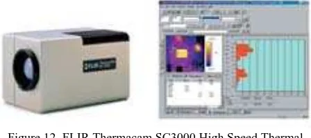
Different surface temperatures are indicated as color variation, giving a measure of the disparity of heat transmission or absorption in the entire region under investigation. Temperature differences of the order of 0.18 ° C can be detected by infrared cameras to the ordinary type, the information is recorded digitally (Figure 12).
The detectability of internal elements, such as voids or thicknesses of the underlying layers, depends on the physical properties (heat capacity, thermal conductivity, density, emissivity) of the materials under investigation.
Figure 12. FLIR Thermacam SC3000 High Speed Thermal Imaging System
Of course everything inside has an effect on the temperature distribution on the surface.
Under different conditions of heating and cooling, areas containing internal voids can show up as either colder or warmer regions. The temperature variation can also be due to
differences in moisture content, the structure of the surface, the emissivity of the material, or reflections due to heat sources nearby. If the temperature varies in the surface, there is a delay before the effect of this change to occur within, where a defect, such as a vacuum, is this: the longer the time interval before the temperature change, the greater the depth of the defect below the surface. Generally elements at depths greater than 10 cm are detected only after a period of time greater than 1 hour after the change of surface temperature (Figure 13).
Figure 13. Façade of Royal Palace in Caserta
Figure 14. Stone cladding on façade of Royal Palace in Caserta
Originally developed in the military in 1960, the infrared thermography has become a widespread technique of investigation aimed to examine the characteristics of masonry building envelopes, including the anomalies due to voids, lesions near the surface, incipient expulsions of material changes in the masonry texture, moisture, plaster hidden objects such as frescoes, mosaics, buffered openings, masonry repairs, internal cavities such as chimneys, flues, or chimneys, thermal bridges.
During the investigation, GPR and paco metrics, aimed at finding the metallic elements, were also carried out some readings with the heating chamber, and where holes or cavities, also of visual inspections with the fiberscope to have a further "Reading" of the acquired data. Figures 13 and 14 contain some images taken with the camera infrared, taken both on the internal walls of the courtyards is exposed on the main façade south, where the greatest temperature difference gave a better analysis to infrared. The selected images produced by the infrared thermal imager developed on different color scale, in
the first place detect the different materials used for interventions maintenance and restoration of the facade of the blocks, in different centuries. In addition, it detects the presence of different metal elements used in appeals of vertical and horizontal joints to equalize the differences in height between the blocks. By the presence of the different colors can also be inferred a degradation layer of very strong at the blocks and between them.
3. CONCLUSIONS
3.1 Georadar and covermeter analysis
During the investigations on the stones of facade was taken over a rectangular wall portion, probably the result of a previous restoration, simply resting, in the absence of any type of binder or adhesive. After removal, it was found that it was not present no element iron. On the other facade was detected a prism portion of a slab, it also under conditions of precarious balance. After removal was
possible to ascertain that the cause, this time, was the presence of an element in iron in advanced oxidation state . GPR scans have first confirmed, also for the portion of facade in question, the same map since stratigraphy obtained from scans on the façade north. . As for the end of the north facade, the "anomalies" were recorded at different depths.
the GPR scans were performed at a distance of few centimeters from the joints between the slabs, and the subsequent processing of the data was based also on the significance of the geometrical position of the lead elements visually detectable, although the latter in this range are very few.The iron elements support the slabs (some of which probably entered on the occasion of restoration), also in this case, show an obvious state of oxidation and do not have a specific rule provision, even those beds to support the slabs shaped coating above the arches that have a greater regularity and repetitiveness in their geometry. Similarly to the north facade, as well as critical due to the oxidation of the metal elements are present also other degradation phenomena, and many traces of operations performed in the past .In addition to the criticality due to oxidation of the metal elements, the elements architectural facade also have other degradation phenomena, that seem to have them already damaged in past eras, as detects the restoration to be put in years ago.To this reason it was decided to perform some petrographic microscopy optics, aimed mainly to the type definition lithological and useful to determining the cause of such degradation.
3.2 Endoscope analysis
Endoscopic examination allows a visual examination of the interior of internal cavities or holes small diameter made in specific parts of the construction. The operation is based on the properties of optical fibers to transmit light by means of successive reflections. Endoscopes, in fact, incorporate optical fibers and an internal light source for illuminate the cavity under examination; have, moreover, a graduated scale in the viewfinder which helps identification and estimation of the size of the observed objects. The image returned is reconstructed with the aid of a computer system, and the main results are presented as images to process and interpret. For the investigation we used a flexible endoscope (fiberscope) PXL XL series PRO which has the particularity of being able to adapt to the change in linearity of the hole, allowing investigations into holes or cavities of at least 10 mm wide. the system program uses a patented system of control of the camera
using a joystick and an articulation All-Way ™ that allow easy positioning and reorientation of the probe, 3.9 mm in diameter. The fiberscope has a high camera
Color resolution (440,000 pixels).
3.3 Thermocam analysis
During the investigation, GPR and paco metrics, aimed at finding the metallic elements, were also carried out some readings with the heating chamber, and where holes or cavities, also of visual inspections with the fiberscope to have a further "Reading" of the acquired data.
The selected images produced by the infrared thermal imager developed on different color scale, in the first place detect the different materials used for interventions maintenance and restoration of the facade of the blocks, in different centuries. In addition, it detects the presence of different metal elements used in riscorsi of vertical and horizontal joints to equalize the differences in height between the blocks. By the presence of the different colors can also be inferred a degradation layer of very strong at the blocks and between them.
4. REFERENCES
References from Library of Soprintendenza per i Beni Ambientali, Architettonici, Artistici e Storici per la provincia di Caserta e Benevento.
1. Gambardella, A. (a cura di), Luigi Vanvitelli
1700-2000, ed. Saccone, Caserta 2005.
2. De Fusco, R., Pane, R., Venditti, A., Di Stefano, R., Strazzullo, F., De Seta, C., Luigi Vanvitelli, ed. Scientifiche Italiane, Napoli 1973.
3. Regia Stamperia, Dichiarazione dei disegni del Reale Palazzo di Caserta, ed. Regia Stamperia, Napoli 1756.
4. Jacobitti, G., Soprintendenza per i Beni Ambientali, Architettonici, Artistici e Storici per la provincia di Caserta e Benevento (a cura di ), Il restauro della facciata e delle
superfici in Bollettino di informazione, restauri, studi, progetti,
notizie, ed. Fausto Fiorentino, Napoli 1994.
5. De Seta, C., Luigi Vanvitelli, ed. Electa, Napoli 1998. 6. Caroselli, M. R., La Reggia di Caserta: lavori, costo,
effetti della costruzione in Biblioteca della Rivista Economia e
Storia, ed. Giuffrè, Milano 1968.
7. Gianfrotta, A., (a cura di ) Manoscritti di Luigi
Vanvitelli in Manoscritti di Luigi Vanvitelli nell’archivio della
Reggia di Caserta 1752 - 1773, Pubblicazione degli archivi di Stato fonti XXX, Ufficio centrale per i Beni archivistici, Ministero per i Beni e le Attività culturali, ed. Edilprint, Perugia 2000.
8. Cundari, C. (a cura di), Il Palazzo Reale di Caserta, Testi ed. Kappa, Roma 2005.
9. AA.VV., Luigi Vanvitelli e il ‘700 europeo, Atti del Congresso Internazionale di Studi Vol I e II, Napoli e Caserta 5-10 novembre 1973, ed. Arte tipografica, Napoli 1973. 10. Marinelli, C., (a cura di), L’esercizio del disegno di
Vanvitelli, ed. Leonardo De Luca Roma 1991.
11. Carbonara, G., (diretto da), Trattato di Restauro
Architettonico, vol. I, ed. UTET, Napoli 1996.
12. Carbonara, G., (diretto da), Trattato di Restauro
Architettonico, vol. II, ed. UTET, Napoli 1996.
13. Carbonara, G., (diretto da), Trattato di Restauro
Architettonico, vol. III, ed. UTET, Torino 1996.
14. Carbonara, G., (diretto da), Trattato di Restauro
Architettonico, vol. IV, ed. UTET, Napoli 1996.
15. Strazzullo, F., Le lettere di Luigi Vanvitelli della Biblioteca Palatina di Caserta Vol I,II e III dal 25- 01- 1751 al
28 - 12 - 1751 n° 48 lettere e dal 01- 01- 1752 al 23 - 06 - 1752 n° 50 lettere, dal 02- 01- 1753 al 31 - 12 - 1753 n° 50 lettere, dal 01- 01- 1754 al 31 - 12 - 1754 n° 94, dal 09-05- 1755 al 27-12-1755 n° 58 lettere, dal 06-01-1756 al 28 - 12 – 1756 n° 83 lettere , dal 01-01-1757 al 31 – 12 – 1757 n°95lettere,dal 03-01-1758 al 31-10-03-01-1758, dal 19-01-1759 al 29-12-1759 n°95 lettere, dal 01-01-1760 al 27-12-1760, dal 03-01-1761 al 29-12-1761 n°96 lettere, dal 02-01- 1762 al 25-12-1762, dal 01- 01- 1763 al 31 - 12 – 1763 n°88 lettere, dal 03- 01- 1764 al 29 - 12 – 1764 n°95 lettere, dal 01- 01- 1765 al 31 - 12 – 1765 n°43 lettere, dal 07- 01- 1766 al 30 - 12 – 1766 n°105 lettere, dal 10- 02- 1767 al 29 - 12 – 1767 n°82 lettere, dal 02- 01- 1768 al 02 - 04 – 1768 n°26 lettere, ed. Congedo, Galatina 1976.
16. Soprintendenza per i Beni Ambientali, Architettonici, Artistici e Storici per la provincia di Caserta e Benevento (a cura di ), Bollettino di informazione, restauri, studi, progetti,
notizie, ed. Fausto Fiorentino, Napoli 1994.
References from Archivio Storico della Soprintendenza per i Beni Ambientali, Architettonici, Artistici e Storici per la provincia di Caserta e Benevento.
17. Documenti tecnici-storici dell’Amministrazione di Caserta e San Leucio, Sezione Marmi e Travertini da pag 552 a 919, Lavori in travertino da pag 583 a 949, Lavori di travertino da pag 621 a 986, Marmi e Travertini da pag.649 a 1013, 678-1041, 711-1072, 750-1108, 821-1176.
Inventari
18. Dispacci e relazioni dal 1755 al 1756. 19. Misure e lavori dal 1770 al 1825
20. Piante e planimetrie di edifici e siti dello stato di Caserta e sue pertinenze sec. XVIII-XIX
21. Conti e cautele dal 1749 al 1756
22. Documenti generali storici dell’Amministrazione di Caserta e San Leucio:
Dispacci e relazioni, Corrispondenze,Relazioni, ordini e dispacci,Registri contabili, Saldaconti, Copialettere, Ruoli, Protocolli, Registri di Magazzino, Registri Real caccia, Pratiche diverse, Misure dei lavori, Conti diversi, Piante topografiche, Segretario economo e dell’agenzia delle tenute,Protocolli di archivio,Giornali, mastri, inventari, permessi.
From: Strazzullo, F., Le lettere di Luigi Vanvitelli della Biblioteca Palatina di Caserta Vol I,II e III ed. Congedo, Galatina 1976:
• Nella lettera del 01-06-1752 Vanvitelli comunica l’inizio della costruzione della Reggia.
• Nella lettera del 21-03-1753 Vanvitelli comunica che il Re ha deciso di rivestire la facciata della Reggia in pietra (dai documenti delle lettere di Vanvitelli al fratello del 1753) • Nella lettera del maggio 1754 Vanvitelli comunica l’innalzamento delle colonne della Reggia (dai documenti delle lettere di Vanvitelli al fratello del 1754)
• Nella lettera del 07-03-1756 Vanvitelli comunica l’inizio dell’ingresso principale della Reggia.
• Nelle lettere del 07-05-1766 Vanvitelli comunica la costruzione della volta dello scalone con il grande ovale al centro e in quella del 03-10-1766 termina il tetto con volte incannucciate.
• Nella lettera el 16-06-1767 Vanvitelli comunica l’inizio delle stuccature nella volta dello scalone e la fine della costruzione delle colonne di facciata verso Napoli
• Nella lettera del 01-03-1757 Vanvitelli comunica che con l’arch. Vaccarini visita la cava di Mondragone per scegliere la pietra per le colonne in facciata.
• Nella lettera del 02-06-1758 Vanvitelli comunica l’inizio del rivestimento in pietra degli archi con l’apposizione in chiave della testa di leone o del giglio borbonico.
• Nella lettera del 08-01-1760 Vanvitelli comunica il termine dei lavori sulla facciata verso Napoli dopo aver innalzato le colonne.
From: Dichiarazione dei disegni del Reale Palazzo di Caserta – Regia Stamperia, Napoli 1756:
I disegni delle piante, pospetti e sezioni originali del Vanvitelli sono solo di progetto architettonico e non materico o tecnologico. Non è stato possibile, quindi, risalire all’idea prìncipe del progetto di rivestimento della facciata.
Incarico del progetto della reggia conferito al Vanvitelli nel 1751 e pubblicazione progetto architettonico nel 1756
Da: Cesare De Seta, Luigi Vanvitelli, ed. Electa, Napoli 1998 I primi schizzi della Reggia furono redatti dal Vanvitelli fra la fine del 1750 e l’inizio del 1751.
Da: F. De Cesaris, Gli elementi costruttivi tradizionali pag.39 in Giovanni Carbonara (diretto da), Trattato di Restauro Architettonico, vol. II, ed. UTET, Napoli 1996
Tecnica tardo ottocentesca: per ancorare il paramento lapideo alla muratura portante, veniva usata la tecnica del “rampone singolo o doppio” ossia di un elemento ferroso a piastra rettangolare o a forma di “C” con le estremità leggermente piegate a seconda che l’ancoraggio era relativo all’elemento lapideo singolo o al punto in cui questo di accostava all’adiacente.
5. ACKNOWLEDGEMENTS
The acknowledgements are directed to Giuseppe Faella, Full Professor of Structures at the Second University of Naples - Department of Architecture and Industrial Design which allowed to use sophisticated equipments of Laboratory ARS of Regional Competences Center Benecon S.C.aR.L.