Digital Signal Processing
DIGITAL SIGNAL PROCESSING
앫 DFT/FFT and Convolution Algorithms and Implementation byC. S. Burrus and T. W. Parks
앫 Digital Signal Processing: Laboratory Experiments Using C and the TMS320C31 DSK
byRulph Chassaing
앫 Digital Signal Processing with the TMS320C25 byRulph Chassaing and Darrell W. Horning 앫 A Simple Approach to Digital Signal Processing
byCraig Marven and Gillian Ewers 앫 Digital Filter Design
byT. W. Parks and C. S. Burrus 앫 Theory and Design of Adaptive Filters
Digital Signal Processing
Laboratory Experiments
Using C and the TMS320C31 DSK
RULPH CHASSAING
University of Massachusetts, Dartmouth
A Wiley-Interscience Publication JOHN WILEY & SONS, INC.
capital or ALL CAPITAL LETTERS. Readers, however, should contact the appropriate companies for more complete information regarding trademarks and registration.
Copyright © 1999 by John Wiley & Sons, Inc. All rights reserved.
No part of this publication may be reproduced, stored in a retrieval system or transmitted in any form or by any means, electronic or mechanical, including uploading, downloading, printing, decompiling, recording or otherwise, except as permitted under Sections 107 or 108 of the 1976 United States Copyright Act, without the prior written permission of the Publisher. Requests to the Publisher for permission should be addressed to the Permissions Department, John Wiley & Sons, Inc., 605 Third Avenue, New York, NY 10158-0012, (212) 850-6011, fax (212) 850-6008, E-Mail: PERMREQ @ WILEY.COM.
This publication is designed to provide accurate and authoritative information in regard to the subject matter covered. It is sold with the understanding that the publisher is not engaged in rendering professional services. If professional advice or other expert assistance is required, the services of a competent professional person should be sought.
ISBN 0-471-20065-4.
This title is also available in print as ISBN 0-471-29362-8.
Preface ix
List of Examples xiii
List of Programs/Files on Accompanying Disk xv 1 DIGITAL SIGNAL PROCESSING DEVELOPMENT SYSTEM 1
1.1 Introduction 1
1.2 DSK Support Tools 2
1.3 Programming Examples to Test the DSK Tools 3
1.4 Additional Support Tools 14
1.5 Experiment 1: Testing the DSK Tools 16
References 17
2 ARCHITECTURE AND INSTRUCTION SET OF THE 19
TMS320C3x PROCESSOR
2.1 Introduction 19
2.2 TMS320C3x Architecture and Memory Organization 21
2.3 Addressing Modes 25
2.4 TMS320C3x Instruction Set 26
2.5 Assembler Directives 30
2.6 Other Considerations 32
2.7 Programming Examples Using TMS320C3x and C code 34 2.8 Experiment 2: TMS320C3x Instructions and Associated Tools 47
References 48
3 INPUT AND OUTPUT WITH THE DSK 51
3.1 Introduction 51
3.2 The Analog Interface Circuit (AIC) Chip 53 v
1
3.3 Interrupts and Peripherals 59 3.4 Programming Examples Using TMS320C3x and C code 60
3.5 PC Host - TMS320C31 Communication 80
3.6 External/Flash Memory and I/O with 16-bit Stereo Audio Codec 87 3.7 Experiment 3: Input and Output with the DSK 88
References 89
4 FINITE IMPULSE RESPONSE FILTERS 91
4.1 Introduction to the z-Transform 91
4.2 Discrete Signals 96
4.3 Finite Impulse Response Filters 97
4.4 FIR Implementation Using Fourier Series 99
4.5 Window Functions 103
4.6 Filter Design Packages 106
4.7 Programming Examples using TMS320C3x and C Code 106 4.8 Experiment 4: FIR Filter Implementation 129
References 131
5 INFINITE IMPULSE RESPONSE FILTERS 135
5.1 Introduction 135
5.2 IIR Filter Structures 136
5.3 Bilinear Transformation 143
5.4 Programming Examples Using TMS320C3x and C Code 150 5.5 Experiment 5: IIR Filter Design and Implementation 160
References 163
6 FAST FOURIER TRANSFORM 165
6.1 Introduction 165
6.2 Development of the FFT Algorithm with Radix-2 165 6.3 Decimation-in-Frequency FFT Algorithm with Radix-2 167 6.4 Decimation-in-Time FFT Algorithm with Radix-2 174
6.5 Bit Reversal for Unscrambling 178
6.6 Development of the FFT Algorithm with Radix-4 179
6.7 Inverse Fast Fourier Transform 183
6.8 Programming Examples Using C and TMS320C3x Code 183
6.9 Experiment 6: FFT Implementation 193
7 ADAPTIVE FILTERS 195
7.1 Introduction 195
7.2 Adaptive Structures 197
7.3 Programming Examples Using C and TMS320C3x Code 199 7.4 Experiment 7: Adaptive Filtering Implementation 221
References 222
8 DSP APPLICATIONS AND PROJECTS 223
8.1 Banks of FIR Filters 223
8.2 Multirate Filter 228
8.3 Pass/Fail Alarm Generator 235
8.4 External Interrupt for Control 239
8.5 Miscellaneous Applications and Projects 242
References 254
APPENDIX A TMS320C3X INSTRUCTION SET AND REGISTERS 257
A.1 TMS320C3x Instruction Set 257
A.2 TMS320C3x Registers 257
Reference 263
APPENDIX B SUPPORT TOOLS 265
B.1 Code Explorer Debugger from GO DSP 265
B.2 Virtual Instrument Using Shareware Utility Package 269 B.3 Filter Design and Implementation Using DigiFilter 271 B.4 MATLAB for FIR/IIR Filter Design, FFT, and Data Acquisition 275
References 281
APPENDIX C EXTERNAL AND FLASH MEMORY 283
C.1 External Memory 286
C.2 Flash Memory 287
References 289
APPENDIX D INPUT AND OUTPUT WITH 16-BIT STEREO 291 AUDIO CODEC
References 298
Index 299
Digital signal processors, such as the TMS320 family of processors, are found in a wide range of applications such as in communications and controls, speech process-ing, and so on. They are used in Fax, modems, cellular phones, etc. These devices have also found their way into the university classroom, where they provide an eco-nomical way to introduce real-time digital signal processing (DSP) to the student.
With the introduction of Texas Instruments’ third-generation TMS320C3x pro-cessor, floating-point instructions and a new architecture that supports features which facilitate the development of high-level language compilers appeared. The C optimizing compiler takes advantage of the special features of the TMS320C3x processor such as parallel instructions and delayed branches. Throughout the book, we refer to the C/C++ language as simply C. Generally, the price paid for going to a high-level language is a reduction in speed and a similar increase in the size of the executable file. Although TMS320C3x/assembly language produces fast code, problems with documentation and maintenance may exist. A compromise solution is to write time-critical routines in TMS320C3x code that can be called from C.
This book is intended primarily for senior undergraduate and first-year graduate students in electrical and computer engineering and as a tutorial for the practicing engineer. It is written with the conviction that the principles of DSP can best be learned through interaction in a laboratory setting, where the student can appreciate the concepts of DSP through real-time implementation of experiments and projects. The background assumed is a system course and some knowledge of assembly lan-guage or a high-level lanlan-guage such as C.
Most chapters begin with a theoretical discussion, followed by representative ex-amples that provide the necessary background to perform the concluding experi-ments. There are a total of 60 solved programming examples using both TMS320C3x and C code. Several sample projects are also discussed.
Programming examples using both TMS320C3x and C code are included throughout the text. This can be useful to the reader who is familiar with both DSP and C programming, but who is not necessarily an expert in both. Although the ix
reader who elects to study the programming examples in either TMS320C3x or C code will benefit from this book, the ideal reader is one with an appreciation for both TMS320C3x and C code.
This book can be used in the following ways:
1. For a laboratory course using many of the Examples and Experiments from Chapters 1-7. The beginning of the semester can be devoted to short program-ming examples and experiments and the remainder of the semester used for a final project.
2. For a senior undergraduate or first-year graduate design project course, using Chapters 1-5, selected materials from Chapters 6-8, and Appendices C and D. 3. For the practicing engineer as a tutorial and for workshops and seminars.
Chapter 1 introduces the tools through three examples. These tools include an as-sembler and a debugger that are provided with the DSP Starter Kit (DSK). Program examples in C can be tested without a C compiler since all associated executables files are on the accompanying disk. Chapter 2 covers the architecture and the in-structions available for the TMS320C3x processor. Special inin-structions and assem-bler directives that are useful in DSP are discussed. Chapter 3 illustrates input and output (I/O) with the two-input analog interface chip (AIC) on the DSK board through several programming examples. An alternative I/O with a 16-bit stereo au-dio codec that can be interfaced with the DSK is described.
Chapter 4 introduces the z-transform and discusses finite impulse response (FIR) filters and the effect of window functions on these filters. Chapter 5 covers infinite impulse response (IIR) filters. Programming examples to implement FIR and IIR filters, in both TMS320C3x and C code, are included.
Chapter 6 covers the development of the fast Fourier transform (FFT). Program-ming examples on FFT are included. Chapter 7 demonstrates the usefulness of the adaptive filter for a number of applications with the least mean square (LMS). Chapter 8 discusses a number of DSP applications.
A disk included with this book contains all the programs discussed in the text. See page xv for a list of the programs/files included on the disk.
years and have contributed to this book as well as to my previous book Digital Sig-nal Processing with C and the TMS320C30.
The support of the National Science Foundation’s Undergraduate Faculty En-hancement (UFE) Program in the Division of Undergraduate Education, Texas In-struments, and the Roger Williams University Research Foundation is appreciated.
1.1 Matrix/vector multiplication using TMS320C3x code 4 1.2 Sine generation with 4 points using TMS320C3x code 8 1.3 Matrix/vector multiplication using C code 11 2.1 Addition of four values using TMS320C3x code 34 2.2 Multiplication of two arrays using TMS320C3x code 35 2.3 Background for digital filtering using TMS320C3x code 37 2.4 Matrix/vector multiplication using TMS320C3x code 42 2.5 Addition using C and C-called TMS320C3x assembly function 42 2.6 Matrix/vector multiplication using C and C-called TMS320C3x 45
assembly function
3.1 Internal interrupt using TMS320C3x code 60 3.2 Sine generation with AIC data using TMS320C3x code 62 3.3 Loop/echo with AIC routines in separate file, using TMS320C3x code 65 3.4 Loop/echo with interrupt using TMS320C3x code 69 3.5 Sine generation with interrupt using TMS320C3x code 70 3.6 Pseudorandom noise generation using TMS320C3x code 70 3.7 Alternative pseudorandom noise generation with interrupt using 73
TMS320C3x code
3.8 Loop/echo with AIC data using C code 75
3.9 Loop/echo Calling AIC routines in separate file, using C code 75 3.10 Loop/echo with interrupt using C code 79 3.11 PC-TMS320C31 communication using C code 82 3.12 Loop control with PC-TMS320C31 communication using C code 84 3.13 Data acquisition with the DSK using C and TMS320C3x code 85 4.1 FIR lowpass filter simulation with 11 coefficients using TMS320C3x 108
code
4.2 FIR bandpass filter simulation with 45 coefficients using TMS320C3x 111 code
4.3 Generic FIR filter specified at run-time, using TMS320C3x code 112 4.4 FIR filter incorporating pseudorandom noise as input, using 115
TMS320C3x code
xiii
1
4.5 Mixed-code FIR filter with main C program calling filter function in 117 TMS320C3x code
4.6 FIR filter with data move using C code 121
4.7 FIR filter using C code 123
4.8 FIR filter with samples shifted, using C code 125 4.9 FIR filter design using filter development package 127 5.1 Sine generation by recursive equation using TMS320C3x code 152 5.2 Cosine generation by recursive equation using TMS320C3x code 154 5.3 Sine generation by recursive equation using C code 154 5.4 Sixth-order IIR bandpass filter using TMS320C3x code 156 5.5 Sixth-order IIR bandpass filter using C code 160
6.1 Eight-point complex FFT using C code 184
6.2 Eight-point FFT with real-valued Input, using mixed C and 187 TMS320C3x code
6.3 Real-time 128-Point FFT using mixed code 191 7.1 Adaptive filter using C code compiled with Borland C/C++ 200 7.2 Adaptive filter for noise cancellation using C code 203
7.3 Adaptive predictor using C code 206
7.4 Adaptive predictor with table lookup for delay, using C code 208 7.5 Adaptive notch filter with two weights, using TMS320C3x code 210 7.6 Adaptive predictor using TMS320C3x code 215 7.7 Real-time adaptive filter for noise cancellation, using TMS320C3x code 218 B.1 FIR filter using Code Explorer for debugging and plotting 265 B.2 FIR filter design and implementation using DigiFilter 272 B.3 IIR filter design and implementation using DigiFilter 274
B.4 FIR filter design using MATLAB 275
B.5 Multiband FIR filter design using MATLAB 276
B.6 IIR filter design using MATLAB 277
B.7 H(z) from H(s) using bilinear function in MATLAB 278 B.8 Eight-point FFT and IFFT using MATLAB 279 B.9 Data acquisition, plotting, and FFT using MATLAB 279 C.1 Multirate filter with 10 bands using external memory and 287
TMS320C3x code
C.2 Sine generation with four points from flash memory, using C code 287 C.3 FIR bandpass filter from flash memory using C code 289 D.1 Loop programs for input and output with the Crystal 16-bit stereo 297
audio codec using TMS320C3x code
README TXT 169
EGAVGA BGI 5363
Directory of CH1
MATRIX ASM 1628
SINE4P ASM 1118
MATRIXC ASM 6860
MATRIXC C 482
MATRIXC CMD 750
MATRIXC OUT 1901
AICCOM31 ASM 5308
Directory of CH2
ADD4 ASM 702
MULT4 ASM 1150
FIR4 ASM 3016
MATRIXMF ASM 1369
ADDMFUNC ASM 556
ADDM ASM 4179
FIR11 ASM 2595
ADDM C 393
MATRIXM C 488
ADDM CMD 804
ADDM OUT 1878
MATRIXM OUT 2053
FIR11L DAT 190
FIR11X DAT 242
1
List of Programs/Files on
Accompanying Disk
xv
Directory of CH3
INTERR ASM 1915
SINEALL ASM 3093
LOOP ASM 838
LOOPI ASM 1076
SINE8I ASM 1539
PRNOISE ASM 1829
PRNOISEI ASM 2214
VECS_DSK ASM 222
LOOPALL ASM 8525
LOOPC ASM 9635
PCLOOP EXE 212306
C31COM ASM 3169
DAQ EXE 250093
DAQ ASM 9627
LOOPALL C 2488
AICCOMC C 2271
LOOPC C 610
LOOPCI C 740
C31COM C 439
C31LOOP C 873
LOOPALL CMD 991
LOOPCI CMD 1029
C31COM CMD 905
C31LOOP CMD 905
LOOPALL OUT 2100
LOOPC OUT 2146
C31LOOP OUT 2856
C31COM OUT 1664
PCCOM CPP 1309
PCLOOP CPP 1033
DAQ CPP 1632
DAQ DAT 3117
DSKLIB LIB 143872
SYMBOLS H 4190
DSKLIB H 293
VECS_DSK OBJ 427
SINEFM ASM 2622
Directory of CH4
BP45SIM ASM 2383
LP11SIM ASM 2385
FIRNC ASM 2147
FIRPRN ASM 3550
FIRMCF ASM 2016
FIRMC ASM 16714
AICCOMC C 2233
FIRDMOVE C 1106
FIRERIC C 1509
FIRMC C 713
FIRC C 1376
FIRMC CMD 1091
FIRDMOVE OUT 3018
FIRERIC OUT 3113
FIRMC OUT 3040
FIRC OUT 3089
BP45SIM DAT 371
LP11SIM DAT 190
FIR BAT 97
FIRPROGA BAS 20237
FIRPROG BAS 17752
BP55 COF 1080
PASS2B COF 1083
PASS3B COF 1088
LP55 COF 1095
BS55 COF 1082
LP11 COF 578
HP55 COF 1079
PASS4B COF 1084
STOP3B COF 1086
BP23 COF 551
BP41 COF 804
BP45 COF 843
BP33 COF 706
COMB14 COF 273
KBP53 COF 2426
RBP53 COF 2424
BP45COEF H 721
Directory of CH5
SINEA ASM 1767
COSINEA ASM 1833
IIR6BP ASM 2335
SINEC C 1971
IIR6BPC C 1057
IIR6BPC CMD 1033
SINEC OUT 3986
IIR6BPC OUT 3115
AMPLIT CPP 17889
BLT BAS 5363
IIR6COEF H 639
SINECMOD C 2456
SINESW ASM 2553
Directory of CH6
TWID128 ASM 2096
FFT_RL OBJ 1011
FFT_RL ASM 6358
TWID8 ASM 221
FFT128C C 2498
FFT C 2294
SINEGEN C 540
TWIDGEN C 814
FFT8C C 680
FFT8MC C 1124
FFT128C CMD 1033
FFT128C OUT 8327
FFT8C OUT 5837
FFT8MC OUT 2985
TWIDDLE H 8557
COMPLEX H 212
FFT8C CMD 922
Directory of CH7
ADAPTP ASM 4110
ADAPTER ASM 3848
ADAPTC C 1684
ADAPTDMV C 1600
ADAPTIVE C 7783
ADAPTSH C 1938
ADAPTTB C 1639
ADAPTDMV CMD 983
ADAPTSH CMD 746
ADAPTDMV OUT 3414
ADAPTSH OUT 5227
ADAPTTB OUT 4543
SIN312 694 SIN312A 776 HCOS312 686 HCOS312A 749 COS312A 798 DPLUSN 730 DPLUSNA 840 SCDAT 3985 SIN1000 647
SHIFT C 812
ADAPTERC ASM 4321
Directory of CH8
MR7DSK ASM 33624
FIR8SETS ASM 10251
FIRALL ASM 10311
MR10SRAM ASM 46118
ALARMGEN ASM 6053
SIM2 C 3803
FIRALL CPP 1226
FIR8SETP 3057
FIRALL EXE 212589
EISINE C 1521
EISINE CMD 1061
EISINE OUT 4307
VEC_DSK ASM 215
VEC_DSK1 ASM 290
SINE4INT C 1454
List of Programs/Files on Accompanying Disk xvii
SINE4INT CMD 947
SINE4INT OUT 4035
SINE4C C 959
SINE4C CMD 959
SINE4C OUT 2317
FIREXT ASM 11292
Directory of APPB
BP45SIMP ASM 2573
BP45SIMP DAT 788
DAQ DAT 3117
MATBP33 COF 594
MAT33 M 523
MAT63 M 544
DAQ M 752
Directory of APPC
SINEHEX C 1254
BP45HEX C 1580
TESTMEM CPP 3690
C31DLHEX CPP 2087
SINEHEX CMD 1015
SINHEX30 CMD 448
BP45HEX CMD 1048
BPHEX30 CMD 471
BP45HEX OUT 3177
BP45HEX A0 4717
SINEHEX OUT 2632
SINEHEX A0 3113
SINEHEX MAP 4439
Directory of APPD
LOOPL_CS ASM 865
LOOPR_CS ASM 848
LOOPB_CS ASM 1015
CSCOM ASM 6646
AM, 156, 163
AMPLIT.CPP utility program, infinite impulse response (IIR) filters, 149–150
Analog interface circuit (AIC) chip, DSK input/output, 53–58
control, 54–55 data configuration, 60
desired Fsand filter BW values, 55–58
loop/echo with C code, 75–79 loop/echo with TMS320C3x code,
65–69
sine generation with TMS320C3x code, 62–65
ARn, TMS320C3x processor, 25 ARn++(d), TMS320C3x addressing, 25 ARn++(d)%, TMS320C3x addressing,
25–26
+ARn(d), TMS320C3x addressing, 25 ++ARn(d)B, TMS320C3x addressing, 25 ARn++(IR0), TMS320C3x addressing, 26 Assembler directives, TMS320C3x
processor, 30–32 Assembly function, TMS320C3x:
C code, addition with, 42–45 matrix/vector multiplication, 5, 45–47
Bandpass filter:
finite impulse response filters, 111–112 infinite impulse response filters:
C code, 160
TMS320C3x code, 156–160 multirate filters, 228–235 Acoustic direction tracker, 242–245
Adaptive filters: background, 195–197
C and TMS320C3x code programming, 199–221
adaptive predictor, C code, 206–210 adaptive predictor, TMS320C3x code,
215–218
C code compiled with Borland C/C++, 200–201
interactive adaptation, 200, 202 noise cancellation, 203–206
notch filter with two weights, 210–215 real-time adaptive filter, noise
cancellation, 218–221 table lookup for delay, adaptive
predictor, 208–210 implementation, 221–222 structure, 197–199 TMS320C30 EVM, 250 Adaptive notch filter:
TMS320C30 EVM, 250
two-weights, TMS320C3x code, 210–215 Adaptive predictor:
adaptive filter system identification, 198 C code programming, 206–210
table lookup delay, 208–210 TMS320C3x programming code,
215–218
ADDM.OUT execution, 45
AIC master clock, sine generation, four points, loading and execution, 10–11 Aliased sinusoidal waveform, DSK
input/output, 52–53
299
Bandstop filters:
finite impulse response (FIR), 117–118 infinite impulse response (IIR), 146–148 Batch file for finite impulse response
filters, generic filter, TMS320C3x code, 114–115
Bilinear transformation (BLT), infinite impulse response (IIR) filters, 143–150
AMPLIT.CPP utility program, 149–150 BLT.BAS utility program, 148
design procedure, 143–145 first-order highpass filter, 146 first-order lowpass filter, 145–146 fourth-order bandpass filter, 147–148 second-order bandstop filter, 146–147 sixth-order bandpass filter, C code,
160–162
sixth-order bandpass filter, TMS320C3x code, 156–160
Bit reversal, fast Fourier transforms (FFT), unscrambling applications, 178–179
Blackman window, finite impulse response filters, 105
BLT.BAS utility program, infinite impulse response (IIR) filters, 148 Boot loader, sine generation, four points,
loading and execution, 9–11 Borland’s C/C++ compiler:
adaptive filter programming, 200 PC host-TMS320C31 communication,
80–82
Branch conflicts, TMS320C3x processor, 32
Branch instructions, TMS320C3x processor, 28–29
Cache, TMS320C3x processor, 33
Cascade structure, infinite impulse response (IIR) filters, 140–141
C code programming: adaptive filters, 199–210
adaptive predictor, C code, 206–210 C code compiled with Borland C/C++,
200–201
interactive adaptation, 200, 202 noise cancellation, 203–206 table lookup for delay, adaptive 300 Index
predictor, 208–210 DSK input/output, 60–80
loop/echo with AIC data, 75–79 loop/echo with interrupt, 79–80 external/flash memory:
FIR bandpass filter, 289 sine generation, 287–289 fast Fourier transform (FFT):
eight-point complex, 184–187 real-time 128-point FFT, mixed code,
191–193
real-valued input, 8-point mixed C and TMS320C3x code, 187–191 finite impulse response filters:
data move, 121–122 filter convolutions, 123–124 flash memory, 285–289 sample shifting, 125–127
infinite impulse response (IIR) filters: sine generation, 154–156
sixth-order bandpass filters, 160–162 linking, 44
matrix/vector multiplication, 45–46 PC host-TMS320C31 communication,
80–87
Circular buffering, TMS320C3x processor, 30
Code Explorer, DSK support, 14 Code Explorer debugger, GO DSP,
265–270
Computer-aided approximation, finite impulse response filters, 105–106 Conflicts, TMS320C3x processor, 32–34 Convolution equation, finite impulse
response filters, 98–99 TMS320C31 memory organization,
106–108
Cosine generation, 152, 154
Crystal CS4216/CS4218 stereo audio codec, DSK input/output, external/flash memory, 88 C3x tools, DSK support, 14–16
Data acquisition:
DSK communications, C and TMS320C3x code, 85–87 MATLAB design, 279–281 Data move applications, finite impulse
Debugger windows, matrix/vector multiplication, TMS320C3x code, 5–7
Decimation-in-frequency FFT algorithm, RADIX-2 development, 167–174 eight-point FFT, 170–172
sixteen-point FFT, 172–174
Decimation-in-time algorithm, fast Fourier transform (FFT), RADIX-2 development, 174–176 eight-point FFT, 176–178 Difference equations, finite impulse
response filters, 95–96 DigiFilter:
DSK support, 14
filter design and implementation with, 271–274
Digital filtering, TMS320C3x code, 37–42 Digital signal processing (DSP):
applications and projects:
acoustic direction tracker, 242–245 external interrupt for control,
239–242
FFT-based security system, 248–249 FIR filter banks, 223–228
harmonic analyzer, 246–247 multirate filters, 228–235 pass/fail alarm generator, 235–239 speech processing for identification,
248
TMS320C30 EVM projects, 250–254 development system, 1–2
DSK support tools, 2–3 support tools, 14–16, 265–281 tools testing, 16–17
Direct form structures, infinite impulse response (IIR) filters, 136–140 Discrete Fourier transform (DFT):
inverse discrete Fourier transform (IDFT), 183
RADIX-2 algorithm development, 165–179
RADIX-4 algorithm development, 179–182
Discrete signals, finite impulse response filters, 96–97
DMA, TMS320C3x processor, 33–34 DSP Starter Kit (DSK), 2
components of, 3
input/output, 51–89
analog interface circuit (AIC) chip, 53–58
external/flash memory with 16-bit stereo audio codec, 87–88 interrupts and peripherals, 59–60 PC host-TMS320C3x communication,
80–87
Euler’s formula, z-transforms of sinusoid, 93–94
External/flash memory: board construction, 283–286 DSK input/output, 87–88 memory decode ranges:
external memory, 286–287 FIR bandpass filter, 289 flash memory, 287 sine generation, 287–289
External and flash memory, DSK support, 14–15
Fast Fourier transform (FFT): background, 165
bit reversal for unscrambling, 178 MATLAB design:
data acquisition, 279–281 eight-point FFT, 279
RADIX-2 algorithm development, 165–170, 174–176
decimation-in-frequency algorithm, 167–174
eight-point FFT, 170–172 sixteen-point FFT, 172–174 decimation-in-time algorithm,
174–179
eight-point FFT, 176–178 RADIX-4 algorithm development,
179–182
sixteen-point FFT, 181–182 TMS320C3x/C code programming:
eight-point complex, 184–187 real-time 128-point FFT, mixed code,
191–193
real-valued input, 8-point mixed C and TMS320C3x code, 187–191 Filter design packages:
Filter development package (FDP), finite impulse response filters, 127–129 Finite impulse response (FIR) filters:
adaptive filter structure and, 197 banks, implementation of, 223–228 Code Explorer debugging and plotting,
265–270
design criteria and techniques, 97–99 DigiFilter design and implementation,
271–274 discrete signals, 96–97 filter design packages, 106
filter development package, 127–129 generic, TMS320C3x code, 112–115 MATLAB design, 275–276, 281
multiband FIR filter, 276–278 s-plane to z-plane mapping, 94–95 window functions, 103–105 Flash memory, construction, 283–286 Floating-point tools, C compilation and
linkage, matrix/vector multiplication, 12–14 FM, 70, 88
Four-channel multiplexer, TMS320C30 EVM, 253
Fourier series, finite impulse response filters, 98–104
window functions, 104–106
Four values addition, TMS320C3x code, 34–35
Frequency shift modulation, TMS320C30 EVM, 253
Generated output frequency, sine
generation, four points, loading and execution, 9–10
Goldwave software: DSK support, 14
virtual instrument shareware, 269–271
Hamming window, finite impulse response filters, 104
Hanning window, finite impulse response filters, 104–105
Harmonic analyzer, 246–247
Highpass filters, infinite impulse response (IIR)filters, 146
Index 302 Image processing, TMS320C30 EVM, 250 Indirect addressing:
bit reversal, fast Fourier transforms (FFT), 178–179
TMS320C3x processor, 25–26 Infinite impulse response (IIR) filters:
AMPLIT.CPP utility program, 149–150 background, 135–136
bilinear transformation (BLT), 143–148 BLT.BAS utility program, 148
cosine generation, recursive equation, TMS320C3x code, 154 cosine generation, TMS320C3x code,
154
design procedure, 143–145
DigiFilter design and implementation, 274
filter structures, 136–143 cascade structure, 140–141 direct form II structure, 137–139 direct form II transpose, 139–140 direct form I structure, 136–137 parallel form structure, 141–143 first-order highpass filter, 146 first-order lowpass filter, 145–146 fourth-order bandpass filter, 147–148 MATLAB design, 277–279
second-order bandstop filter, 146–147 sine generation, recursive equation, C
code, 154–156
sine generation, TMS320C3x code, 152–154
sixth-order bandpass filter, C code, 160–162
sixth-order bandpass filter, TMS320C3x code, 156–160
Input/output:
DSK support, 51–89
analog interface circuit (AIC) chip, 53–58
16-bit stereo codec, 15, 88 interrupts and peripherals, 59–60 PC host-TMS320C3x communication,
80–87
TMS320C3x and C code programming examples, 60–87
16-bit stereo audio codec design, 291–298
loop programs, 297–298 TMS320C3x instruction, 28
Instruction sets, TMS320C3x processor, 26–30, 257–260
branch instructions, 28–29 circular buffering, 30 input/output instructions, 28 load and store instructions, 27–28 math instructions, 27
parallel instructions, 260
repeat and parallel instructions, 29–30 Interactive adaptation, adaptive filter, C
code programming, 200–202 Interactive implementation, FIR filter
banks, 225–228 Interrupts:
DSK input/output, 59
internal, with TMS320C3x code, 60–62
loop/echo using C code, 79–80 loop/echo using TMS320C3x code,
69–70
sine generation using TMS320C3x code, 70
external control, 239–242 Inverse fast Fourier transform (IFFT):
eight-point IFFT, 183 MATLAB design, 279
Kaiser window, finite impulse response filters, 105
Laplace transform, finite impulse response filters, 91–92, 94
Least mean square algorithm (LMS), adaptive filter structure, 196–197, 199
Linking command, 13
Load and store instructions, TMS320C3x, 27, 257
Loop/echo programs, 75–80 AIC routines using C code, 75–79 AIC routines using TMS320C3x code,
65–69
crystal 16-bit stereo audio codec, 297–298
interrupt using TMS320C3x code, 69–70
Lowpass filters:
finite impulse response (FIR) filter: Fourier series, 101–103
TMS320C3x simulation, 108–110 infinite impulse response (IIR) filter,
145–146
Math instructions, TMS320C3x processor, 27
MATLAB software:
data acquisition, plotting and FFT, 279–281
eight-point FFT and IFFT, 279 filter design, 275–279, 281 infinite impulse response (IIR) filter
design, 277–279
multiband FIR filter design, 276–278 real-time FIR/IIR filter design, 281 Matrix/vector multiplication:
C and C-called function, 45–47 C code, 11–14
TMS320C3x, 4–7, 42 Memory access:
external/flash memory, 286–289 organization, 21–25
TMS320C3x processor, 33
Memory conflicts, TMS320C3x processor, 33
Mixed-mode FIR filter, C and TMS320C3x code, 117–121
Multiband FIR filter design, MATLAB design, 276–278
Multirate filter, 228–235 design criteria, 228–233
external and TMS320C3x code, 287 implementation, 233–235
TMS320C30 EVM, 250
Neural networks, TMS320C30 EVM, signal recognition, 253–254
Noise cancellation: adaptive filter:
C code, 203–206
real-time filter, TMS320C3x code, 218–221
adaptive filter structure, 197 TMS320C30 EVM, 250
Parallel form structure, infinite impulse response (IIR) filters, 141–143 Parametric equalizer, TMS320C30 EVM,
250
Pass/fail alarm generator, programming for, 235–239
PC host-TMS320C31 communication: C code, 81–87
library support file DSKLIB.LIB, Borland’s C/C++ compiler, 81 support header file DSKLIB.H, 80–81 PID controller, TMS320C30 EVM, 251 Pseudorandom noise:
finite impulse response filters, 115–117 pass/fail alarm generator, 238–239 Pseudorandom noise generation,
TMS320C3x code, 70–74
RADIX-2 algorithm development, fast Fourier transform (FFT), 165–179 decimation-in-frequency algorithm,
167–174
decimation-in-time algorithm, 174–178 RADIX-4 algorithm development, fast
Fourier transform (FFT), 179–182 sixteen-point FFT, 181–182
Read-only memory (ROM), 34
Real-time adaptive filter, noise cancellation, TMS320C3x code, 218–221 Recursive equation, infinite impulse
response (IIR) filters: cosine generation, 154 sine generation, 152–156
Recursive least squares (RLS) algorithm, adaptive filter structure, 199 Register conflicts, TMS320C3x processor,
32–33 Registers:
interrupt enable (IE), 261 interrupt flag (IF), 263 status (ST), 261
Repeat and parallel instructions, 29–30 RIDE40, DSK support, 15
Sample shifting, finite impulse response filters, C code, 125–127
Sampling frequency (Fs), sine generation,
four points, loading and execution, 10–11
Index 304 Security system design, fast Fourier
transform (FFT), 248–249 Serial port, DSK input/output, 59 SigLab, DSK support, 15
Signal generator, DSK support tool, 2 Signal recognition, TMS320C30 EVM,
neural networks, 253–254 Signal/spectrum analyzer, DSK support
tool, 2 Sine generation:
C code, 154–156 DSK input/output:
AIC data using TMS320C3x, 62–65 interrupt using TMS320C3x, 70 external/flash memory, 287–289 four points, TMS320C3x code, 8–11 TMS320C3x code, 150–154 16-bit stereo/audio codec:
DSK input/output, 87–88 input/output, 291–298
Speech processing for identification, 248–249
s-plane mapping, finite impulse response filters, z-plane mapping, 94–95 Swept frequency response, TMS320C30
EVM, 250
Taylor series approximation, finite impulse response filters, z-transforms of exponential functions, 92–93 Timers, DSK input/output, 59 TMS320C30 EVM projects, 250–254 TMS320C3x:
adaptive filters, 210–221
adaptive predictor, TMS320C3x code, 215–218
real-time adaptive filter, noise cancellation, 218–221 addressing modes, 25–26
architecture and memory organization, 21–25
conflicts, 32–34 CPU registers, 22–25
crystal 16-bit stereo audio codec: FIR filter, 298
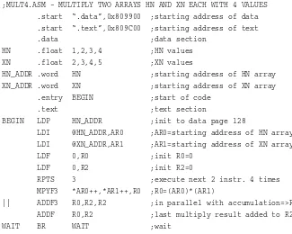
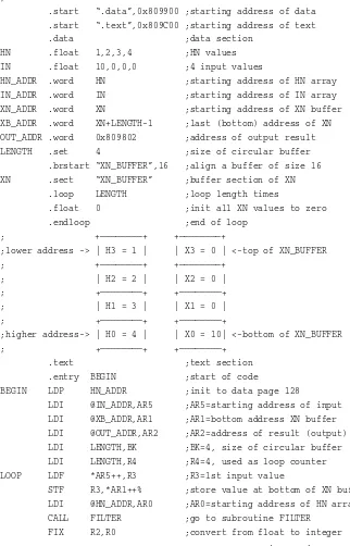
Two arrays multiplication, TMS320C3x code, 35–37
Two-weighted notch structure, adaptive filters, 198
Unscrambling, bit reversal, fast Fourier transforms (FFT), 178–179
Video line rate analysis, TMS320C30 EVM, 250–251
Virtual bench, DSK support, 14 Virtual instrument, shareware utility
package, 269–271
Wait states, TMS320C3x processor, 34 Window functions, finite impulse response
filters, 103–106
Wireguided submersible, TMS320C30 EVM, 251–253
z-transform, finite impulse response filters, 91–96
ZTof exponential function, 92–93 ZTof sinusoid, 93–94
loop/echo with AIC routines, 65–69 loop/echo with interrupt, 69–70 pseudorandom noise generation, 70–74 functional block diagram, 22–23
sine generation with AIC data, 62–65 sine generation with interrupt, 70 external memory, multirate filter, 287 finite impulse response filters, 106–121
generic filter specification, 112–115 lowpass filter simulation, 108–110 mixed-mode filter, C program calling,
117–121
infinite impulse response (IIR) filters: cosine generation, 152, 154 sine generation, 150–154
sixth-order bandpass filter, 156–160 instruction set, 26–30, 257–260 memory organization, 21–25 registers, 22–25, 257, 259, 261–263 TMS320 floating-point DSP assembly
language tools, DSK support, 2–3 Tools testing, DSK experiments, 16–17 Transfer functions, finite impulse response
앫 Use of the TMS320C31 DSK
앫 Testing the software and hardware tools such as the debugger
앫 Programming examples in C and TMS320C3x code to test the tools
Chapter 1 introduces several tools available for digital signal processing (DSP). These tools include the TMS320C31-based DSP Starter Kit (DSK) with com-plete input and output support. Three examples are included to illustrate these development tools and, in particular, to test the DSK.
1.1 INTRODUCTION
Digital signal processors, such as the TMS320C31, are just like fast micro-processors with a specialized instruction set and architecture appropriate for signal processing. The architecture of a digital signal processor is very well suit-ed for numerically intensive calculations. These processors are ussuit-ed for a wide range of applications from communications and controls to speech and image processing. They are found in music synthesizers, cellular phones, fax/modems, etc. They have become the product of choice for a number of consumer applica-tions, since they can be very cost-effective. DSP techniques have been very suc-cessful because of the development of low-cost software and hardware support. For example, applications such as modems and speech recognition can be less expensive using DSP techniques. Furthermore, general-purpose digital signal processors can handle different tasks, since they can be readily reprogrammed for a different application. While analog-based systems with discrete electronic components such as resistors can be more sensitive to temperature changes,
1
1
Digital Signal Processing
Development System
DSP-based systems are less affected by environmental conditions such as tem-perature.
Books and articles have been published that address the importance of digi-tal signal processors for a number of applications [1–17]. Various technologies have previously been used for signal processing. The more common applica-tions using DSP processors have been for the audio-frequency range from 0 to 20 kHz, for which they have been very suitable. Speech can be sampled at 10 kHz, which implies that each sample or value is acquired at a rate of 1/(10 kHz) or 0.1 ms. For example, a commonly used sample rate (how quickly samples are acquired) of a compact disk (CD) is 44.1 kHz.
The basic system consists of an analog-to-digital converter (ADC) to cap-ture an input signal. The resulting digital representation of the capcap-tured signal is then processed by a digital signal processor such as the TMS320C31 and then output through a digital-to-analog converter (DAC). Also included within the basic system is a special input filter for antialiasing to eliminate erroneous signals, and an output filter to smooth or reconstruct the processed output sig-nal.
Most of the work presented here involves the design of a program to imple-ment a DSP application.
1.2 DSK SUPPORT TOOLS
To perform the experiments, the following tools are needed:
1. Texas Instruments’ DSP Starter Kit (DSK), which includes a board with the TMS320C31 floating-point processor and input and output (I/O) sup-port. The DSK board contains an analog interface circuit (AIC) chip that provides for programmable ADC and DAC rates, and input and output fil-tering, all on a single chip. Software tools for assembling and debugging as well as several applications examples are also included with the DSK package [18].
2. An IBM compatible PC. The DSK board connects to the parallel printer port in the PC, through a DB25 cable provided with the DSK package. 3. An oscilloscope, signal generator, speakers, and signal/spectrum analyzer
(optional). Shareware utilities are available that utilize the PC and a sound card to create a virtual instrument such as an oscilloscope, a function gen-erator, or a spectrum analyzer (see Section 1.4 and Appendix B).
this book and included on the accompanying disk, as long as these pro-grams are not modified.
The DSK based on the TMS320C31 (C31) is a relatively powerful, yet inex-pensive ($99) development board for real-time digital signal processing. The DSK board contains the TMS320C31 processor and the TLC320C40 analog in-terface circuit (AIC) chip for input and output [18].
The assembler provided with the DSK creates an executable file that can be directly downloaded into the C31 on the DSK and run. It does not create a COFF file, which is obtained using the TMS320 floating-point DSP assembly language tools. The DSK assembler does not include or require a linker. Code is assembled at an absolute address into specified memory sections using cer-tain assembler directives. These directives serve as a linker and can be used to include or chain several files together (discussed in Chapter 2). The assembled executable file can be loaded into the C31 on the DSK by using the debugger or boot loader provided with the DSK package, as illustrated later in this chapter.
1.3 PROGRAMMING EXAMPLES TO TEST THE DSK TOOLS
Three examples are introduced to illustrate the DSK tools. Don’t worry about the program code at this point, since these programs are only to test the tools, in particular, the DSK. All the programs discussed in this book are on the accom-panying disk. The programs coded in TMS320C3x or assembly language were assembled using the DSK software tools version 1.22. The latest version of these tools is available from Texas Instruments’ FTP site at FTP.TI.COM.
1. The DSK package includes a User’s Guide manual, a DB25 parallel print-er cable, and a disk that contains the assemblprint-er, debuggprint-er, and various utilities and applications examples [18,19]. The DSK (board) requires a DC adapter that provides 7.5–12 Volts DC or an AC adapter that provides 6–9 Volts AC; both must supply a minimum of 400 milliamps [18]. Adapters with lower voltage or amperage specifications than recommended should not be utilized. When pow-ered up, the light on the DSK board should change color (green and red). When the DSK is not properly connected, it is usually because of the parallel port se-lection. For example, the address is 0x378 for LPT1 (by default). If that port ad-dress is already being used, select another communication port (0x278 for LPT2 or 0x3BC for LPT3). RCA type connectors are available on the DSK board for input and output.
2. Create a directory dsktoolsand install the software tools provided on the disk included with the DSK package. Add dsktoolsto the path in your
hard drive. The number of active files should be limited to 20 when using the debugger by setting FILES = 20in your config.sysfile.
Example 1.1 Matrix/Vector Multiplication Using TMS320C3x Code
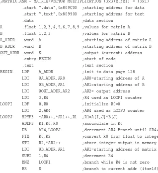
This example illustrates the use of some of the tools. Don’t worry at this point about the program code. Figure 1.1 shows a listing of the MATRIX.ASM pro-gram to multiply a (3 × 3) matrix Aby a (3 × 1) vector B, or
;MATRIX.ASM - MATRIX/VECTOR MULTIPLICATION (3x3)x(3x1) = (3x1) .start “.data”,0x809C00 ;starting address for data .start “.text”,0x809900 ;starting address for text .data ;data section
A .float 1,2,3,4,5,6,7,8,9 ;values for matrix A B .float 1,2,3 ;values for matrix B
A_ADDR .word A ;starting address of matrix A B_ADDR .word B ;starting address of matrix B OUT_ADDR .word $ ;output (current) address
.entry BEGIN ;start of code .text ;text section
BEGIN LDP A_ADDR ;init to data page 128 LDI @A_ADDR,AR0 ;AR0=starting address of A LDI @B_ADDR,AR1 ;AR1=starting address of B LDI @OUT_ADDR,AR2 ;AR2= output address LDI 3,R4 ;R4 used as LOOPI counter LOOPI LDF 0,R0 ;initialize R0=0
LDI 2,AR4 ;AR4 used as LOOPJ counter LOOPJ MPYF3 *AR0++,*AR1++,R1 ;R1=A[I,J]*B[J]
ADDF3 R1,R0,R0 ;accumulate in R0
DB AR4,LOOPJ ;decrement AR4.Branch until AR4<0 FIX R0,R2 ;convert R0 from float to integer STI R2,*AR2++ ;store integer output in memory LDI @B_ADDR,AR1 ;AR1=starting address of matrix B SUBI 1,R4 ;decrement R4
BNZ LOOPI ;branch while R4 is not zero BR $ ;branch to current addr (itself)
FIGURE 1.1 Matrix/vector multiplication program using TMS320C3x code
1 2 3 1 14
冤
4 5 6冥 冤
2冥
=冤
32冥
7 8 9 3 50
that yields a (3 × 1) vector containing the result (14, 32, 50). All the programs discussed in this book are included on the accompanying disk.
Assembling
Assemble the source program MATRIX.ASMby typing:
dsk3a matrix.asm
The asmextension is not necessary, but it is a good practice to name the source file with an extension asm. The assembler creates the executable file MA-TRIX.DSK (not case-sensitive) that can be downloaded into the C31 on the DSK and run using either the debugger or the boot loader (boot loading is illus-trated in Example 1.2).
Loading an Executable File Into the DSK to Run To invoke the debugger, type:
dsk3d
If the debugger is not successfully invoked, check for proper power supply con-nection and the parallel printer port setup in your PC. The DSK concon-nection to the parallel port on the PC defaults to LPT1. [18].
The C31 processor should always be reset before running a program. Within the debugger, you can reset the C31 with the command:
reset
Then load the executable file MATRIX.DSKby typing the command:
load matrix.dsk
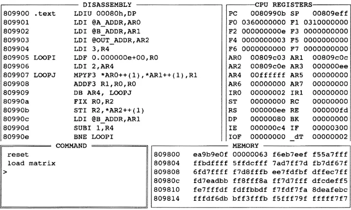
These commands are not case-sensitive and the extension dskis not necessary. The debugger screen should now look as in Figure 1.2.
Note that the program code starts at the memory location 809900, as shown in the first column within the DISASSEMBLY window. The hexadecimal nota-tion 0xis implied. The first column represents the instruction memory address and the second column represents the instruction opcode.
C31 is listed in Appendix A; however, don’t worry for now about the code. The right-top window screen shows that AR0contains the value 809c00, which is the starting address in memory where the nine values of the matrix Aare stored.
AR1 contains the value 809c09, the starting address in memory where the three values of the vector Bare stored; and AR2contains 809c0e, the starting memory address for the three resulting output values. The matrix Amultiplied by the vector Byields the values e, 20, 32 in hex, equivalent to the decimal val-ues 14, 32, 50.
In Chapter 2, we will see that AR0–AR7are eight registers on the C31 that are often used to designate a specific address in memory that contains an in-struction or a data value. F0–F7represent the eight registers R0–R7that are often used to contain a data value. The C31 has 2K words (32-bit) of internal or on-chip memory (16 million memory spaces total); 809800(in hex) represents the starting address of this block of internal memory.
2. Access the MEMORY window using ALT-M (the ALT key together with M). Use the down-arrow key to scroll down from 809800, the memory address in the first column, to 809c00. Or, press ESCto access the command window and type mem 0x809c00to display the contents in memory start-ing at the address 809c00. The notation 0x is necessary with a command. Press F1 for help on available debugger commands. The data values stored starting at memory address 809c00 are in floating-point format which you
need not to worry about. The floating-point value 00000000 corresponds to a decimal value of 1.
Type memf 0x809c00to display the content in memory in float (decimal) format starting at the address 809c00. Verify that the nine values of the matrix Aare stored in memory starting at the address 809c00, followed by the three values of the vector B, starting at the address 809c09.
3. As you single-step through the program and execute each time the in-struction STI R2,*AR2++(1), observe the register window within the de-bugger (top-right window screen), which displays the contents of the CPU reg-isters in hexadecimal format, by default. Press F3and verify that each resulting value 14, 32, 50 is contained in F0, which represents the register R0. Also, ver-ify from the MEMORY window that the resulting output values e, 20, 32 in hex are stored in memory starting at the address 0x809c0e, specified in AR2. The three resulting values in memory locations 809c0e, 809c0f, and 809c10
can be displayed in 32-bit hex format or in 32-bit signed format (decimal) with the commands memx 0x809c0eor memd 0x809c0e, respectively. While a debugger command is not case-sensitive, the 0x notation for hexadecimal is re-quired.
Press F2 or F3 to display the CPU registers in 32-bit hex format or float for-mat, respectively. The F’s represent the float of the extended precision registers
R0–R7. These registers are on the C31 and displayed as F0–F7within the CPU registers window screen.
4. Run the program again by typing resetand load matrixfrom the COMMAND window, and press F5 to run. Then, press ESCto stop execution, since the instruction BR WAITto branch back to itself (to wait) is still being executed continuously. Note that F0= 50, the last result.
5. Reset and load again the matrix program. Press ALT-D to access the DISASSEMBLY window. Use the down-arrow key to scroll down to the STI R2,*AR2++(1)instruction at the address 80990b. Press F2 to toggle or set a breakpoint, which will highlight the instruction set with the breakpoint. Press F4 to run until breakpoint. Note that the program counter (PC) contains
80990b, the address of the instruction to be executed next. Press F8 once to execute that instruction. Verify from the MEMORY window that the content in memory location 809c0eis the first resulting value of 14 (ein hex). Press F4 again to run until the set breakpoint, then F8 to execute the instruction STI R2,*AR2++(1)a second time, and verify the second resulting value 32 in memory location 809c0f. Repeat this process a third time to verify the third resulting value of 50 in memory location 809c10.
We will see in Chapter 2 that the instruction STI R2,*AR2++(1)stores each result from R2into a memory location specified by AR2. The register AR2
is incremented for each output value and contains the address in memory where each result is stored. In this fashion, AR2is used as a “pointer,” pointing to a memory address. Type quitfrom the command window to exit the debugger.
Example 1.2 Sine Generation with Four Points Using TMS320C3x Code
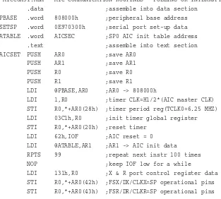
This example illustrates the generation of a sinusoid using a table look-up method. There are two RCA connectors next to the light on the DSK board, one for input and the other for output. Connect the DSK output to a speaker to hear a generated tone or to an oscilloscope to view the generated sinusoidal wave-form. An analog interface circuit (AIC) chip, on board the DSK, provides I/O capabilities and will be discussed in Chapter 3.
Section 1.4 and Appendix B describe several tools available as virtual instru-ments that can utilize the PC and a sound card as an oscilloscope or as a spec-trum analyzer. For example, while the C31 on the DSK is running, the share-ware utility Goldwave can be accessed and run as an oscilloscope to verify the generated output sinusoid. The output of the DSK would then be connected to the input of a sound card (such as Sound Blaster) plugged on a PC.
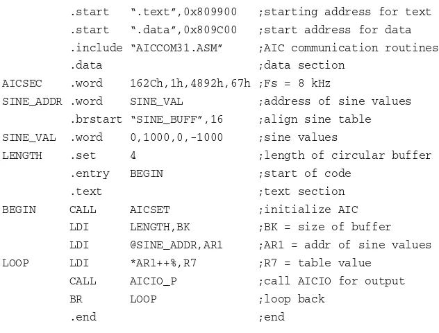
Figure 1.3 shows the program listing SINE4P.ASM, which generates a tone using four points. Again, don’t worry about the code for now, since the empha-sis is to become more familiar with the tools. This program invokes (includes) another program AICCOM31.ASM(on the accompanying disk), which contains several routines for communication with the on-board AIC for real-time input
FIGURE 1.3 Sine generation program using TMS320C3x code (SINE4P.ASM).
;SINE4P.ASM - GENERATES A SINE USING ONLY 4 POINTS
.start “.text”,0x809900 ;starting address for text .start “.data”,0x809C00 ;start address for data .include “AICCOM31.ASM” ;AIC communication routines .data ;data section
AICSEC .word 162Ch,1h,4892h,67h ;Fs = 8 kHz
SINE_ADDR .word SINE_VAL ;address of sine values .brstart “SINE_BUFF”,16 ;align sine table
SINE_VAL .word 0,1000,0,-1000 ;sine values
LENGTH .set 4 ;length of circular buffer .entry BEGIN ;start of code
.text ;text section BEGIN CALL AICSET ;initialize AIC
LDI LENGTH,BK ;BK = size of buffer LDI @SINE_ADDR,AR1 ;AR1 = addr of sine values LOOP LDI *AR1++%,R7 ;R7 = table value
CALL AICIO_P ;call AICIO for output BR LOOP ;loop back
and output capabilities. While we will discuss the AIC in Chapter 3, we will mostly use the AIC communication routines by simply “including” the file
AICCOM31.ASMin other programs (fourth line in SINE4P.ASM).
1. Assemble the program SINE4P.ASMonly and not AICCOM31.ASM. 2. Access the debugger, reset the C31 processor as in Example 1.1, and load the program SINE4P.DSK.
3. Press F5 to run and verify a tone with a frequency of 2 kHz. The frequen-cy fof the resulting output waveform is obtained using:
f= Fs/(number of points)
where Fs= 8 kHz is the sampling frequency, which also designates the output
sample rate. This rate determines how fast an output sample point representing the generated sinusoidal waveform is produced. The sampling rate is specified by the A/D and D/A converters on the AIC. Although there is no external input, an output sample point is generated every T= 1/Fs= 0.125 ms, where T
repre-sents the sampling period.
Loading and Executing Using the Boot Loader
Run the sine generation program by invoking a boot loader program provided with the DSK software tools. This procedure does not access the debugger. Type
dsk3load sine4p.dsk
to load and run this program. Verify that a 2-kHz signal is generated. Again the extension dsk is not necessary. Care must be exercised when running a pro-gram with the boot loader, since it does notreset the C31. Erroneous values can result, for example, if an interrupt-driven program (interrupt will be discussed in Chapter 3) was previously loaded into the C31. In such cases, use the debug-ger to reset the C31.
Don’t modify the original programs on the accompanying disk. Before mak-ing any changes to any file on the accompanymak-ing disk, copy it first into your hard drive.
1. Changing the number of points to change the generated output fre-quency. a) Replace the four points specified in the program (9th line) with the following eight points:
0, 707, 1000, 707, 0, –707, –1000, –707
SINE8P.ASMand should not be assembled separately. Verify a generated sinu-soidal tone with a lower pitch or frequency, f= 8,000/8 = 1 kHz.
b) Replace the eight-point sequence with 12 points taken every 30 degrees from a sinusoid, i.e., 0, 500, 866, . . . , –500, and scaled. Change the length to 12. Verify a generated output sinusoidal tone with a frequency of f= 8,000/12 = 666.66 Hz.
2. Changing the sampling frequency Fs. Four values are defined/set in
AICSEC(6th line in SINE4P.ASM). The first and third values specify the AIC sampling frequency Fs. Change these values such that AICSECis set to:
0E1Ch, 1h, 3872h, 67h
which specifies a sampling frequency Fs= 16 kHz, as will be shown in Chapter
3. These four values are specified in hex with an h after each value (or 0x before the value). Reassemble the program SINE4P.ASMand use the boot loader to load and run this program. Verify that the frequency of the new generated sinu-soid is 4 kHz, since
f= 16,000/(number of points)
3. Changing the AIC master clock to change Fs. The first and the third value specified in AICSEC are calculated in Chapter 3 using a specific value for the AIC master clock. Changing the master clock frequency proportionately changes the sampling frequency Fs.
a) Back up the file AICCOM31.ASM (on disk) and change the instruction (twelfth line in the program):
LDI 1,R0
to LDI 0,R0, which doubles the AIC master clock and effectively doubles the sampling frequency Fswith the values specified in AICSEC. Reassemble the
original program SINE4P.ASMwith a four-point look-up table and a frequen-cy set for 8 kHz. Note that the file AICCOM31.ASMshould notbe assembled separately. Since it is “included” or incorporated in the program SINE4P.ASM, only that program is to be assembled. Use the boot loader to run the resulting executable file SINE4P.DSK. Verify that the generated output signal has a fre-quency of 4 kHz since the new sampling frefre-quency is 16 kHz, or
f= 16,000/4 = 4 kHz
since Fsis effectively reduced from 8 kHz to 4 kHz. Let k= 4, and verify that
the generated output signal frequency is
f= (8,000/k)/4 = 500 Hz
Example 1.3 Matrix/Vector Multiplication Using C code
You can test and run all the C-program examples in this book, since all the re-sulting executable files, compiled/assembled and linked with the TMS320 float-ing-point assembly language tools, are included on the accompanying disk. However, if the C-source file is modified, it will need to be compiled, assem-bled, and linked again.
Running C Programs Without the Floating-Point Tools
The source program MATRIXC.Clisted in Figure 1.4 is the C version of the program MATRIX.ASM in Example 1.1. Access the debugger as in Example 1.1. Reset the C31 by typing the debugger command:
reset
1.3 Programming Examples to Test the DSK Tools 11
FIGURE 1.4 Matrix/vector multiplication program using C code (MATRIXC.C).
/*MATRIXC.C - MATRIX/VECTOR MULTIPLICATION */ main()
{
volatile int *IO_OUTPUT = (volatile int *) 0x809802; float A[3][3] = { {1,2,3},
{4,5,6}, {7,8,9} }; float B[3] = {1,2,3};
float result; int i,j;
for (i = 0; i < 3; i++) {
result = 0;
for (j = 0; j < 3; j++) {
result += A[i][j] * B[j]; }
*IO_OUTPUT++=(int)result; /*result start in mem addr 0x809802*/ }
Then, within the debugger type the command
load matrixc.out
to load the executable COFF file MATRIXC.OUT(not case-sensitive) supplied on the accompanying disk. The extension OUT is not necessary, since the de-bugger detects such type of executable COFF file as opposed to an executable file with a dskextension.
Single-step through the program up to the instruction STI RS,*AR0at the memory address 80983e. Note that there is much initialization code added from compiling. The STIinstruction causes each resulting output value to be stored in consecutive memory, starting at the address pointed by AR0, which contains the output address 809802. Verify the three resulting values e, 20, 32 in hex. Type memd 0x809802to verify from the memory-window screen the three resulting values 14, 32, and 50 stored in memory addresses
809802–809804.
The DSK does not support a C-source debugger. Hence, the C-source file cannot be displayed through the DSK debugger window screen. With a C-source debugger, one could single-step through an instruction in C and observe the corresponding steps through equivalent assembly instructions [1, 23]. Tools that support debugging capabilities, such as the C3x debugger for the evaluation module (EVM), are available from Texas Instruments [25], and Code Composer is available from GO DSP (see Section 1.4)
C Compiling and Linking Using Floating-Point Tools
a) Compiling/Assembling. This section illustrates the use of the TMS320 floating-point DSP assembly language tools, version 5.0 [21–23]. These tools are not included with the DSK package. The C-code programs in this book were compiled/assembled and linked with these tools. Compile/assemble the C-source program MATRIXC.C, by typing:
cl30 -k matrixc.c
The extension c is not necessary. This creates the source file MATRIXC.ASM
as well as the object file MATRIXC.OBJ. Various compiler options are avail-able [22]. The -koption is to retain the assembly source file MATRIXC.ASM, since the CL30command compiles and assembles. Different levels of optimiza-tion are available for compiling. Using CL30 -o3selects the highest optimiza-tion level (register, local, global, and file) for faster execuoptimiza-tion speed. The -o2
A source file in TMS320C3x assembly code such as MATRIX.ASMcan be assembled with the floating-point tools using the command
ASM30 MATRIX.ASM
to create the object file MATRIX.OBJ. Note that the command CL30 MATRIXC.Ccompiles and assembles in one step.
b) Linking.Link the resulting object file MATRIXC.OBJusing the sample linker command file MATRIXC.CMDlisted in Figure 1.5 (on the accompanying disk), by typing:
lnk30 matrixc.cmd
This creates the executable file MATRIXC.OUT. This is a linked common-ob-ject file format (COFF), popular in Unix-based systems and adopted by several makers of digital signal processors. The COFF format makes it easier for modu-lar programming and managing code segments [24].
Note that the comments /* and */ used in C programming have the same functions in the linker command file MATRIXC.CMDshown in Figure 1.5. The 1.3 Programming Examples to Test the DSK Tools 13
FIGURE 1.5 Linker command file for C coded matrix example (MATRIXC.CMD).
/*MATRIXC.CMD - LINKER COMMAND FILE */ -c /*using C convention */ -stack 0x100 /*256 words stack */ matrixc.obj /*object file */ -O matrixc.out /*executable output file */ -l rts30.lib /*run-time library support*/ MEMORY
{
RAMS: org=0x809800, len=0x2 /*boot stack */ RAM0: org=0x809802, len=0x3FE /*internal block 0*/ RAM1: org=0x809C00, len=0x3C0 /*internal block 1*/
} SECTIONS
{
-loption invokes the file RTS30.LIBincluded with the floating-point tools, which is an object-library file that contains run-time support C functions. Don’t worry for now about the MEMORY and SECTIONS specifications within the linker command file.
1.4 ADDITIONAL SUPPORT TOOLS
The following tools can be useful in conjunction with the DSK (see also Appen-dix B).
1. Code Exploreris a free, scaled-down version of the popular debugger Code Composer, available from GO DSP [26]. It can be retrieved at the web site address www.go-dsp.com. as a zipped file and pkunzipped. An executable dsk
file can be readily downloaded into the Code Explorer and run. A sequence of data stored within consecutive memory locations can be plotted in both the time and frequency domains within the Code Explorer debugger environment and saved on disk. The debugger includes capabilities to single-step, run to break-point, and modify memory/register (see Appendix B). An example on filtering is described in Appendix B to illustrate the use of the Code Explorer as a debug-ger for running a program and plotting the resulting output within the debugdebug-ger environment. The programs in Examples 1.1 and 1.2 can be tested with the Code Explorer debugger.
Code Explorer does not support COFF executable files. Code Composer, with appropriate documentation, can be purchased from GO DSP and allows you to download and execute COFF or DSK files.
2. Goldwave,a shareware virtual instrument (goldwave.zip), can be used as an oscilloscope or as a spectrum analyzer in conjunction with a PC and a sound card such as Sound Blaster [27]. Goldwave can also be used to generate func-tions such as a sinusoidal signal with a specified frequency or random noise (see Appendix B). It can be retrieved at the web address www.goldwave.com.
3. DigiFilteris a filter-design package that supports the DSK and is avail-able from MultiDSP at [email protected]. It is illustrated in Appendix B in conjunction with filtering, discussed in Chapters 4 and 5. The designed filter characteristics can be downloaded directly into the DSK and run to implement a filter in real time [28].
4. Virtual Bench is a virtual instrument available from National Instru-ments (which produces LabView) at www.natinst.com. With a data acquisition card that plugs onto a PC slot and an I/O board for input and output, Virtual Bench can be used as a function generator, as an oscilloscope, or as a spectrum analyzer.
in the flash memory section and run on the DSK without any connection to a PC. This daughter board connects directly to the DSK through the four 32-pin connectors along the edge of the DSK board. All the TMS320C31 signals are routed to these four expansion connectors on the DSK and are available for the optional use of daughter boards with external memory or with alternative I/O capability, as described in Chapter 3 and Appendices C and D.
6. Input/Output Alternative with 16-bit Stereo Codec.Appendix D de-scribes a board that interfaces to the DSK and contains Crystal’s CS4216 (or CS4218) 16-bit stereo audio codec with two complete channels for input and output. An evaluation board based on the CS4216 (or CS4218) codec is avail-able from Crystal Semiconductors.
7. SigLab is a virtual lab (box) with support software, available from DSPTechnology at [email protected]. The SigLab box is interfaced to a PC via an SCSI connector. A two-channel, 20-kHz bandwidth and a four-channel with a 50-kHz bandwidth are available. The SigLab box includes a TMS320C31 for real-time signal processing and two fixed-point digital signal processors from Analog Devices for filtering support. SigLab, while connected to the PC through an SCSI interface, can be accessed for real-time input generation and output monitoring while the DSK is also running. For example, it can be used as an oscilloscope or as a spectrum analyzer through one channel on the SigLab box connected to the output on the DSK, while generating signals such as a two-tone sinusoid or random noise through another SigLab channel connected to the input on the DSK.
8. RIDE40, available from Hyperception at [email protected] is a virtual design tool that can be used to implement DSP algorithms. It contains a wide range of functional blocks for FFT, correlation, filtering, etc., and can be used for both simulation and real time. Within a few minutes, one can design and test a DSP system that includes functional blocks such as sine generators, filters, and the FFT. Results can be displayed on the PC monitor or to an exter-nal device such as an oscilloscope. However, it currently supports the C30-based EVM but not the C31-C30-based DSK.
Digital filters can be readily designed with a filter package available from Hyperception.
9. Updated DSK and C3x Tools.Texas Instruments’ web site contains the most recent version of the C31 DSK software tools. These tools include the as-sembler and debugger as well as several support and applications examples. The DSK software tools, version 1.22, were used to assemble the programs dis-cussed in this book. Texas Instruments’ FTP site is: FTP.TI.com. Select C3xdsk-tools to retrieve the updated software support C3xdsk-tools for the C31 DSK.
Several applications examples are included with the DSK software package (first, assemble the support source files with the asmextension) such as:
b. DSK_SG.EXE to obtain a signal generator with the following func-tions: sine (SINE_SG.ASM), ramp (RAMP_SG.ASM), random (RAND_SG.ASM), and sawtooth (SAWT_SG.ASM). Test the sine genera-tor and verify that several sinusoidal signals with different frequencies can be added and the resulting waveforms generated.
c. DSK_WAV.EXEcalls DSKWAV files. Speech can be recorded as input to the DSK, then played back.
Application programs on the fast Fourier transform (FFT), discussed in Chapter 6, are also included with the DSK package. For example,
FFT_512.EXEimplements a 512-point FFT.
1.5 EXPERIMENT 1: TESTING THE DSK TOOLS
This experiment illustrates the use of the tools, in particular, the software and hardware support tools associated with the DSK.
1. Perform/implement the matrix program MATRIX.ASM in Example 1.1. This assembly program executes faster than its C-coded counterpart MA-TRIXC.C, discussed in Example 1.3, even though it is longer and looks more difficult.
2. Perform/implement the sine generator program in Example 1.2.
3. Perform/implement the C-code matrix program discussed in Example 1.3. Note that both the source file MATRIXC.Cas well as the executable file
MATRIXC.OUTare included on the accompanying disk. It is not necessary to have the TMS320 floating-point DSP assembly language tools in order to run the C programs included in this book. However, if you modify a C program, then you need these tools in order to recompile it and relink to create an exe-cutable file that can be run on the DSK. The C compiler command CL30 MA-TRIXC.C compiles and assembles to create both the TMS320C3x assembly source code MATRIXC.ASM and the object file MATRIXC.OBJ. This object file is linked with a run-time library support file RTS30.LIBto create the ex-ecutable COFF file MATRIXC.OUT that can be loaded directly into the DSK and run.
4. Echo program. Run the program LOOP.ASMon the accompanying disk, referred to as a “loop” or echo program. To test this program, connect to the in-put of the DSK a sinusoidal signal from a function generator with an amplitude of approximately 1–3 V and a frequency between 1 and 3 kHz. Observe a de-layed output sinusoidal signal of the same frequency. Vary the input frequency between 1 and 3 kHz and verify the same change in the frequency of the output signal. The values set from AICSECin the loop program LOOP.ASMspecify a sampling frequency of Fs= 8 kHz and a bandwidth of approximately 3,550 Hz
internal input filter, on-chip the AIC, called antialiasing filter. Increase the in-put signal frequency above this bandwidth and verify that it is attenuated or cut-off by the internal input filter on-chip the AIC. Deleting this input filter will cause aliased output signals which we will verify in Chapter 3 (Example 3.3).
5. Test some of the applications examples that are provided with the DSK package.
REFERENCES
1. R. Chassaing, Digital Signal Processing with C and the TMS320C30,Wiley, New York, 1992.
2. R. Chassaing and D. W. Horning, Digital Signal Processing with the TMS320C25,Wiley, New York, 1990.
3. P. Papamichalis ed., Digital Signal Processing Applications with the TMS320 Family: Theory, Algorithms, and Implementations,Texas Instruments, Inc., Dallas, TX, Vol. 3, 1990.
4. K. S. Lin ed., Digital Signal Processing Applications with the TMS320 Family: Theory, Algorithms, and Implementations,Prentice Hall, Englewood Cliffs, NJ, Vol. 1, 1988. 5. R. Chassaing, “Applications in digital signal processing with the TMS320 digital signal
processor in an undergraduate laboratory,” in Proceedings of the 1987 ASEE Annual Conference, June 1987.
6. P. Lapsley, J. Bier, A. Shoham, and E. Lee, DSP Processor Fundamentals Architectures and Features,Berkeley Design Technology, 1996.
7. R. Chassaing, W. Anakwa, and A. Richardson, “Real-Time Digital Signal Processing in Education,” in Proceedings of the 1993 International Conference on Acoustics, Speech and Signal Processing (ICASSP),April 1993.
8. R. Chassaing and B. Bitler (contributors), “Signal Processing Chips and Applications,” The Electrical Engineering Handbook,CRC Press, Boca Raton, FL, 1997.
9. S. A. Tretter, Communication System Design Using DSP Algorithms,Plenum Press, New York, 1995.
10. R. M. Piedra and A. Fritsh, “Digital Signal Processing Comes of Age,”in IEEE Spec-trum,May 1996.
11. Y. Dote, Servo Motor and Motion Control Using Digital Signal Processors,Prentice Hall, Englewood Cliffs, NJ, 1990.
12. I. Ahmed, ed., Digital Control Applications with the TMS320 Family,Texas Instruments, Inc., Dallas, TX, 1991.
13. A. Bateman and W. Yates, Digital Signal Processing Design,Computer Science Press, New York, 1991.
14. R. Chassaing, “The Need for a Laboratory Component in DSP Education—A Personal Glimpse,” Digital Signal Processing,A