Committee
of the First Makassar International Conference on Civil
Engineering
SCIENTIFIC COMMITTEE * Prof. Dennes T. Bergado (Thailand) * Prof. Toshimitsu Komatsu (Japan) * Prof. Tetsuro Esaki (Japan) * Prof. Shigenori Hayashi (Japan) * Prof. Shinji Kawabe (Japan) * Prof. Jinchun Chai (Japan) * Prof. Yan-Jun Du (China)
* Prof. Indrasurya B. Mochtar (Indonesia) * Prof. Herman Parung (Indonesia) * Prof. Mahmood Md. Tahir (Malaysia) * Prof. Robert J. Verhaeghe (Netherland) * Prof. Dadang Ahmad Suriamiharja (Indonesia) * Bambang Trigunarsyah, PhD (Australia) * Marolo Alfaro, PhD (Canada)
ADVISORY COMMITTEE * South Sulawesi Governor * Rector of Hasanuddin University * Dean of Engineering Faculty
* Head of Civil Engineering Department * Secretary of Civil Engineering Department * Prof. Mary Selintung
* Prof. Lawalenna Samang * Prof. Herman Parung * Prof. Wihardi Tjaronge
* Prof. Dadang Ahmad Suriamiharja * Dr. Arsyad Thaha
* Dr. Sakti Adji Adisasmita * Dr. Rudi Djamaluddin
ORGANIZING COMMITTEE Chairman
Prof. M. Saleh Pallu Co-Chairman Dr. Tri Harianto Secretary
Ardy Arsyad, MEng Bambang Bakri, MEng St. Hijraini, MEng
Asiyanthi T. Lando, MEng Treasurer
Irwan Ridwan, MEng Members
Dr. Mukhsan P. Hatta
M. Asad Abdurrahman, MEng Muralia Hustim, MEng Silman Pongmanda, MEng Rosmariani Arifuddin, MEng Kartika Sari, MEng
Proceedings of the First Makassar International Conference on Civil Engineering (MICCE2010), March 9-10, 2010, ISBN 978-602-95227-0-9
EFFECTS OF GROIN PERMEABLE ON FLOW VELOCITY
Hasdinar Umar1, Nur Yuwono 2, Radianta Triatmadja 3, and Nizam4
ABSTRACT: The Roughness in the open channel are inhibiting factor which depends on the amount of resistance characteristics such as the roughness of channel. This paper investigates the vertical piles in the flow through the open channel which act as hydraulic roughness affecting the flow behaviors. The purposes of this research are to study the reduction coefficient that affects the magnitude of flow velocity in the open channel due to the resistance of vertical piles. The Research based on the influence of the vertical piles to the flow has been studied by previous researchers. The results of those studies explained that the vertical piles can reduce the flow velocity due to the increase of the shear stress ().
This research uses the structure of the model structure vertical a pile in 2D open channel with the width of channel is 0.6 m and the length is 10 m. The distance between the model structures is determined as two times length of the model structure (2L) and the distance between the vertical piles (G) is 0.7 cm..
The results showed that with the arrangement of the vertical piles, flow rate is reduced compared to the conditions of open channel without a vertical pile structure. The shorter the distance between the pile and the bigger the pile diameter to be used, the smaller the Chezy coefficient is become. Therefore the resistance becomes bigger then the velocity reduced.
Keywords: flow, velocity, vertical piles, resistance.
1Lecturer, Hasanuddin University, Makassar 90222, INDONESIA 2
Professor, Gadjah Mada University, Yogyakarta 55281, INDONESIA
3
Professor, Gadjah Mada University, Yogyakarta 55281, INDONESIA
4
Professor, Gadjah Mada University, Yogyakarta 55281, INDONESIA INTRODUCTION
The Flow in the open channel is a fluid flow through channels with free surface. Phenomenon of flow in open channel with a varieties flow conditions has been studied by hydraulic engineers. The Roughness in the open channel are inhibiting factor which depends on the amount of resistance characteristics such as the roughness of channel. Groin piles in the flow through the open channel acts as a hydraulic roughness affects the flow. Flow velocity distribution with the constraints of a groin is essential to determine the parameters affecting the flow velocity changes. Some research of groin has been investigated by several previous researchers such as Raudkivi (1996), examine the groin permeable form of vertical piles in the southern Balitic Sea, in Raudkivi (1996) explained that groin permeable form of vertical columns act as hydraulic roughness on the coast parallel currents. Bakker et al (1984) and Kolp (1970) in Raudkivi (1996) stated that the groin piles can reduce the flow velocity parallel to the coast until about half of the current speed compares it without piles groin, so that it can be said that groin piles serve as barriers for flow of current parallel to the coast. Vertical piles can also reduce the intensity of turbulence on the sea floor around the pile.
THE DRAG FLOW
Flow through an object (either fully or partially submerged), then the object will get the force direction of the flow. This force is called drag. The amount of drag will be influenced by parameters as follows:
1)
shape (Sb),2)
the projection area of the object in the plane perpendicular to the direction of flow (A
),3)
flow velocity (V
),4)
fluid density (
), dan5)
viscosity (
).The relation between the drag forces with those parameters can be written by:
S
,
A
,
V
,
,
f
F
D
b(1)
Using dimensional analysis the equation can be expressed in the form of:
22 1
,
S
A
V
R
f
F
D
e b
e b
Df
R
S
C
,
D
C
is the resistance coefficient (drag) which is a function of Reynolds number (Re) and the shape (Sb). CDfor cylinder is 1,2.
2 2
1
A
V
C
F
D
D
(3)THE FLOW CLASSIFICATION
The flow can be classified into types by the criteria:
1. Laminar and turbulent flow
Laminar flow is a steady flow, fluid particles move along smooth lines layers by layers of a smooth glide with the other neighboring layers. Laminar flow can be observed in the fluid that has a high viscosity and low velocity.
The turbulent flow of fluid particles move in the direction that causes irregular change of momentum, mass and energy from one part to another fluid. In Chow, 1997, the ratio of inertial forces to the viscous force per unit volume is known as the Reynolds number (Re). Reynolds number can be written as follows:
L
U
R
e
(4) where
U
= velocity (m/sec);L
= length (m);
= kinematic viscosity (m2/sec) = 1,004 x 10-6The following values are Reynolds number limitation of fluid flow characteristics in open channel flow: Re 500 laminar flow
500 < Re 2000 transitional flow Re 2000 turbulent flow
2. Subcritical and supercritical flow
Comparison of inertial forces to gravitational forces per unit volume is known as the Froude number (Chow, 1997), can be written
as:
D
g
V
F
r
(5)
where
F
r= Froude number;V
= velocity (m/sec);g
= the acceleration due to gravity (m2/sec);D
= hydraulic depth (m)Flow critical to say the same if the Froude number 1, the flow is called subcritical if the Froude number is less than 1 and the flow of supercritical Froude numbers when more than 1. Subcritical flow is sometimes called balance flow while the term rapid flow and flow
incubate (shooting flow) is also used to express the flow supercritical.
TECHNICAL PARAMETER IN OPEN CHANNEL
a. Discharge
Discharge is the amount of liquid flowing through a cross-flow per unit time. Discharge was measured in liquid volume per unit time. In an ideal liquid, is considered not having friction with the edge of the channel, either open channel or pipe. So the speed has the same value for every point in the look of latitude. Flow equation through a cross-section is described as follows:
A
V
Q
(6)where:
Q
= discharge (m3/sec);V
= average velocity (m/sec);A
= flow cross-sectional area perpendicular to the direction of flow (m2)b. Hydraulic Radius
Hydraulic radius of a look in the flow equation can be formulated as follows:
P
A
R
(7)
where
R
= hydraulic radius (m);A
= wet cross-sectional area flow (m2);P
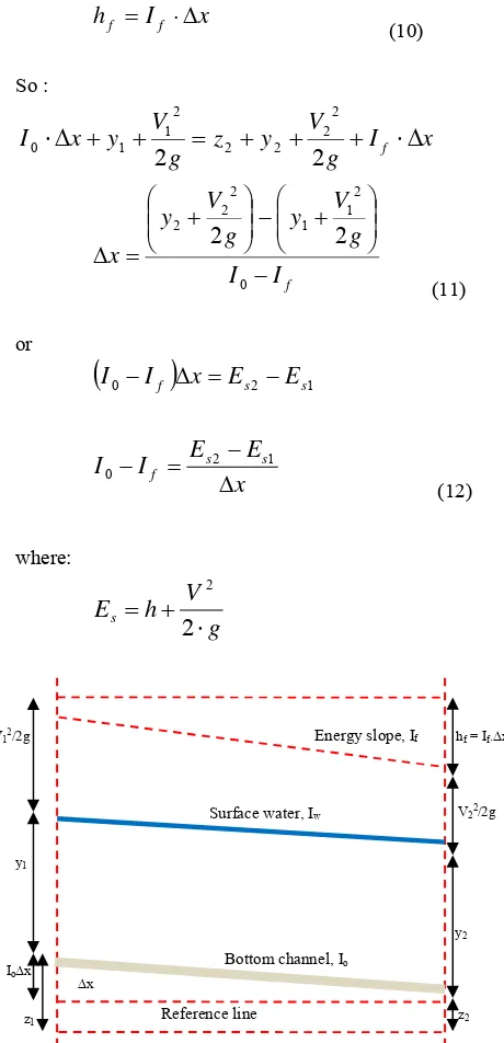
= wet cross-section circumference (m)c. Energy Slope
One method of solving problems is an open channel with direct step method. In this method, the channel division is done in pale with each breath. Starting from the end of the downstream boundary where the hydraulic characteristics of the expression are known, calculated water depth along the channel. Direct step method is a simple method that can be used for prismatic channels. Figure 1 shows a pale under review for calculations. Assumption that the velocity distribution is a uniform in latitude and Coriolis is taken as 1, then :
hf
g
V
y
z
g
V
y
z
2
2
2 2 2 2 2 1 1 1
(8)
Remembering :
x
I
z
z
z
1 2 0 (9)x
Figure 1. Part channels to reduce direct step method
d. Chezy coefficient
Energy slope
I
f is the average energy of 1 and 2 expression. So that the Chezy coefficient values can be searched with a length of pale (
x
). Chezy coefficient (C
) can be calculated by using Equation 13.I
FLOW THROUGH VERTICAL PILE BARRIERS
Flow through a vertical pile barriers on the open channel is influenced by 2 type of shear stres, which are:
a. Shear stress between the base with water channels b. Shear stress between the vertical piles with water
Shear stress equation of flow through a vertical pile constraints can be formulated as follows
o= 1+ 2 (14)
whereo= total shear stress (kg/m 2.sec);
Shear stress between the vertical piles with water is a relationship between large stems, number of stems and the coefficient of drag (CD). This is becaused the function of vertical piles is becoming barriers to the flow therefore it can be formulated resistance force to the flow of the vertical piles.
2
force to shear stress.
2 vertical pile obtained Chezy coefficient equation of flow through a vertical pile resistance with the influence of the channel bottom roughness:
hf= If.∆x
Energy slope, If
Surface water, Iw V22/2g
y2
z2
Bottom channel, Io
L
Permeability of the Vertical Pile Structure
Permeability structure of the vertical pile structure is the ratio between the distances between the vertical piles and the diameter of pile multiplied with ratio of width of the channel and the length of the groin.
% length of the groin (m).
Flow Velocity (3-62)
Velocity of flow through open channel with Chezy equation is:
V
C
R
.
I
(21)Chezy coefficient in the equation of flow through a vertical pile barrier permeability function pile structure of the vertical structure (equation 19) substituted into equation 21 so that the flow velocity equation obtained through a vertical pile constraints as follows:
I
permeability of vertical pile structure (%); b = wisech of the channel (m); G = the distance between the piles; I = energy slope; l = length of the groin (m)
REDUCTION COEFFICIENT
Groin can reduce flow velocity, the value of speed reduction can be approached with the equation
Vt = K. Vo (23) K = Vt / Vo (24)
where Vt = velocity with groin (m/sec); Vo = velocity without groin (m/sec); K = reduction coefficient.
Reduction coefficient is the function of barrier groin structure.
LABORATORY RESEARCH
The model vertical piles have the following design specifications:
a. Diameter of pile is 1.25 cm
b. Number of pile length varies in accordance with the structure, L = 45 cm and L = 30 cm
c. The distance between piles in a row model G = 0.7 cm, the permeability of the structure = 0.5 d. The distance between the model 2L
Equipment used in this study are as follows.
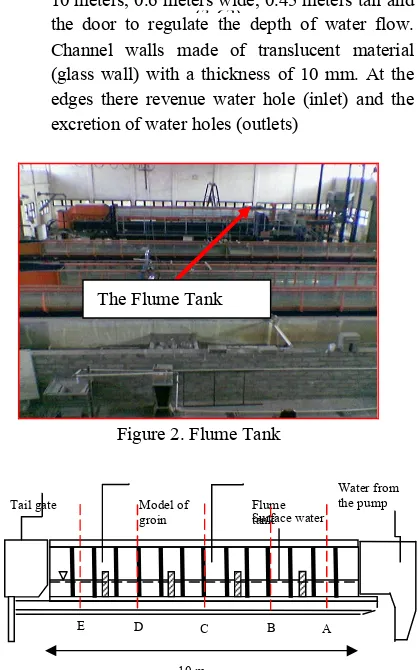
1. Flume tanks, lines of material flexiglass its entirety consists of a channel with a length of 10 meters, 0.6 meters wide, 0.45 meters tall and the door to regulate the depth of water flow. Channel walls made of translucent material (glass wall) with a thickness of 10 mm. At the edges there revenue water hole (inlet) and the excretion of water holes (outlets)
Figure 2. Flume Tank
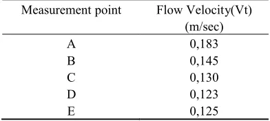
Figure 3. Scheme of the flume tank and model of groin (Side View)
The Flume Tank
10 m Tail gate Model of
Figure 4. Scheme of the flume tank and model of groin (front view)
2. Water pump to provide flow simulation in accordance with the planning. The depth of water in the channel is set using the Flan attached to one end while the rate of flow channels can be set according to the use by adding or subtracting using rounds pedal (pedal jack). The stability of the flow velocity can be checked by looking at a high moving water or high difference in the orifice tube is inserted in the pipe income (inlet) cannel
3. Point Gauge to measure the depth of flow 4. Stopwatch is used to record the time of
measuring the velocity at the time of calibration 5. Current meter for measuring the velocity at
points that were reviewed
6. Camera for documentation and stationery for recording of research results
RESEARCH RESULTS
Discharge Flow
Discharge simulation used in this study is :
Table 1. Data flow calibration results
Discharge recorded (lit/sec)
Real Discharge (lit/sec) Y = 0.988x + 0.916 10
15
10.796 15.736
Flow velocity
Flow velocity measurements obtained from the laboratory, can be seen in the table below.
Table 2. Data of flow velocity measurements in the condition without the model
Measurement point Flow Velocity (Vo) (m/sec) A
B C D E
0,533 0,48 0,48 0,48 0,474
Table 3. Data of flow velocity measurements in the condition with the model
Measurement point Flow Velocity (Vt) (m/sec) A
B C D E
0,286 0,257 0,257 0,237 0,228
Table 4. The results of theoretical calculations on the flow rate condition without a groin model.
Measurement point Flow Velocity (Vo) (m/sec) A
B C D E
0,24 0,25 0,25 0,26 0,52
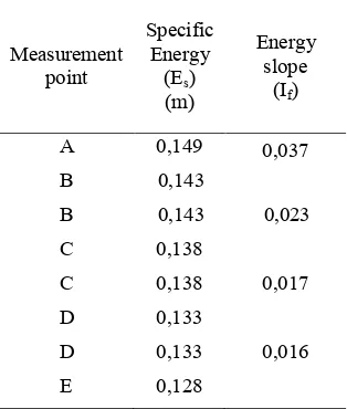
Table 5. The results of theoretical calculations on the flow rate condition with a groin model (Cd = 0.9)
Measurement point Flow Velocity(Vt) (m/sec) A
B C D E
0,183 0,145 0,130 0,123 0,125
Flow Depth
The depth of the flow obtained through the observation wall of water on the glass and through a channel measurement using a point gauge.
b = 0,6 m l
G
1 6
Model of groin vertical piles
Energy Slope
Energy slope ( If ) is specific energy difference in both look long divided by pale (x). Energy slope can be calculated by using equation 13.
The results of calculations are given in Table in below
Table 5. The results of the energy slope (without groin)
Measurement point
Specific Energy
(Es)
(m)
Energy slope
(If)
A 0,121 0,002
B 0,120
B 0,120 0,002
C 0.118
C 0,118 0,001
D 0,117
D 0.117 0,003 E 0,114
Table 6. The results of the energy slope (with groin)
Measurement point
Specific Energy
(Es)
(m)
Energy slope
(If)
A 0,149 0,037
B 0,143
B 0,143 0,023
C 0,138
C 0,138 0,017
D 0,133
D 0,133 0,016
E 0,128
Chezy Coefficient Without Groin
Flow trough the channel without piles is a common condition that occur the water through a channel without barriers. Chezy coefficient calculation results are presented in table 7.
Table 7. Chezy coefficient without groin
Measurement point
Flow Velocity
(Vo) (m/sec))
Energy slope
(If)
Chezy coeffient
(C1)
A 0.533 0.002 42.4
B 0.48
B 0.48 0.002 38.4
C 0.48
C 0.48 0.001 54.6
D 0.48
D 0.48 0.003 31.5
E 0.474
Chezy Coefficient With Groin
Equation 19 can be used to calculation the Chezy coefficient with groin. Chezy coefficient calculation results are presented in table 8.
Table 8. Chezy coefficient with groin
Measurement point
Flow Velocity
(Vt) (m/sec))
Energy slope
(If)
Chezy coeffient
(C1)
A 0.286 0.037 5.6
B 0.257
B 0.257 0.023 6.5
C 0.257
C 0.257 0.017 7.7
D 0.237
D 0.237 0.016 7.4
E 0.228
DATA ANALYSIS
Flow velocity through Barriers Groin Pile Vertical
The Alteration of flow velocity due to resistance model groin vertical pile can be seen in the picture below.
From the picture above can be seen that the rate of flow after there is a groin model is lower than the rate of flow without a groin model. This indicates that the groin vertical piles serve as barriers to the flow and can reduce the velocity.
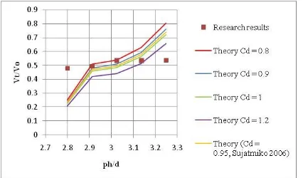
Flow velocity before and after there is model is in theory the pile model can be calculated by equation 22. The relationship between the ratio of the velocity without the model (Vo) and the velocity with a model (Vt.) with a dimensionless coefficient ph / d, can be seen in the picture below.
Figure 6. Compare the relationship Vt. / Vo research and theory with coefficient ph / d
From the picture above can be seen that the coefficient reduction is about 0,5 (research results) and the line of the closest relationships with the research results is the line between the coeffiecient of drag (Cd)
0.9 and 1, so that it can concluded that the value of the coefficient of drag (Cd) is 0.95. Coefficient of drag is
influenced by the number of vertical piles, the distance between piles, and the diameter of the pile. So the need for the further research on the effect of the number, diameter and permeability of the groin against the coefficient drag. As can be seen in the research Sujatmiko (2006), the drag coefficient values obtained were 0.95 for the number of vertical piles and more vertical piles are closer together. Therefore it can be said that the drag coefficient is affected by the number of piles, the density of the distance between the piles and the pile diameter.
CONCLUSION
1. Coefficient reduction is about 0,5 so the groin vertical pile can reduce the flow velocity of the flow velocity half before there is no groin vertical pile
2. Chezy equation for flow through a vertical pile barriers can be seen that the Chezy coefficient
directly proportional to the permeability model groin, so it can be concluded that the smaller the permeability model groin (the distance between the piles closer), the Chezy coefficient will also be getting smaller and the flow velocity will provide smaller.
3. Coefficient of drag (Cd) value that gives the results of theoretical research approach is about 0.95.
ACKNOWLEDGEMENTS
This study is supported by the Laboratory of Hydrology Hydraulic, Engineering Studies Center, Gadjah Mada University, Yogyakarta.
REFERENCES
Chow, V.T., 1997, Hidraulika Saluran Terbuka (Open Channel Hydraulics), Erlangga, Jakarta.
Raudkivi, 1996, Permeable Pile Groin, Journal of Waterway, Port, Coastal and Ocean engineering ASCE, 122.
Raju K.G.R., 1986, Aliran Melalui Saluran Terbuka, Erlangga, Jakarta.
Stone B.M. and Shen H.T., 2002, HydraulicResistance of Flow in Channels with Cylindrical Roughness, Journal of Hydraulic Engineering ASCE, 128(5), 500 – 506
Streeter, V.L., Wylie, E.B., 1988, Mekanika Fluida, Jilid 1, Edisi 8, Erlangga, Jakarta.
Sujatmiko, 2006, Equivalensi Nilai Koefisien Chezy Pada Aliran Terhambat Batang Vertikal, Master Tesis, Gadjah Mada University, Yogyakarta. Yuwono N., 1992, Dasar-dasar Perencanaan Bangunan
Pantai, Hydraulic dan Hydrology Laboratory, PAU IT Gadjah Mada University, Yogyakarta. Yuwono N., 1996, Perencanaan Model Hidraulik