Advances in Applied Physics, Vol. 3, 2015, no. 1, 23 - 34 HIKARI Ltd, www.m-hikari.com
http://dx.doi.org/10.12988/aap.2015.576
Application of Compass and Range Sensors on
Eyeglass for Blind People Based on
Microcontroller AT89S52
I Gede Surya Adi Pranata1 and Anak Agung Ngurah Gunawan1
1 Department of Physics University of Udayana at Bali Indonesia
Copyright © 2015 I Gede Surya Adi Pranata and Anak Agung Ngurah Gunawan. This article is
distributed under the Creative Commons Attribution License, which permits unrestricted use, distribution, and reproduction in any medium, provided the original work is properly cited.
Abstract
24 I Gede Surya Adi Pranata et al.
12 of 15 people success in reaching two destinations as check point that given in this trial, so successfulness of this tool is 80%.
Keywords: Ultrasonic wave, PWM, UART, Timer, Microcontroller
1.
Introduction
Blindness is the reduction of visual ability that resulting to degeneration of mobility ability [5]. These limitations often make their activity risky. Frequently complaint of blind people on their activity is blunder against standing object, especially for object like notification board, branch of the tree, opened window, etc, that can’t detected using the cane, because the cane is only used to detect object below the thigh so the object that exist over the tight can’t detected immediately and can be risky for head. The other thing that is also important for blind people to get safety walking is reference for determine their walking direction to reach their destination and to avoid get lost on new unknown environment. Cardinal direction information is one of reference that very useful to blind people, for example ; determine walking direction, recognizing of new environment become faster, understanding the cardinal direction instruction those given by normal people, and determine direction for blind people. Some supporting tool for blind people had been developed by some company, but if the purpose is only to help blind people on their mobility, that tools can be said expensive. Some researching had been done to help blind people with cheaper cost, for example; Application of infra-red sensor for obstacles detection [2], application of ultrasonic sensor that applied on shoulder and cane [4], application of ultrasonic sensor on the cane with speech output [8] and application of ultrasonic sensor on spectacles and waist belt [7]. But all of these tool can’t be used for determine cardinal directions which giving big contribution for blind people to determine walking direction, based on that reason, a supporting tool for obstacle detection and cardinal direction determination with sound output based on microcontroller AT89S52 is made. With this tool, a blind people also can projecting their destination properly beside to anticipate unpredictable obstacle continually without physical contact.
2.
Materials and Methods
A. Obstacles detection
Obstacles detection using ultrasonic sound wave at 40,000 Hz which produced by Ultrasonic Range Finder HC-SR04, because of ultrasonic sound wave is not influence by color of the object as infra-red sensor, so it make ultrasonic sound wave more reliable to be used in this application. Pin out configuration of HC-SR04 is shown at Figure 2.1. HC-SR04 application is by giving high pulse with 10μ duration then ultrasonic transmitter will produces 8 cycle of ultrasonic sound wave at 40 kHz, then echo pin will produce PWM pulse
Application of compass and range sensors 25
from transmitter to obstacle and reflected back to receiver [9], so this PWM duration is to be measure by program to find the range.
Figure 2.1 Pin Configuration of HC-SR04
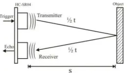
Based on datasheet of HC-SR04, maximum range to be measurement by this ultrasonic range finder is 400 cm with accuracy up to 3 mm, and blind spot under 2 cm. Then using program, the measurement is limited at 400 cm to avoid hang on the program if over range is occur. Working principal of ultrasonic range finder is shown at Figure 2.2
Figure 2.2 Working principal of Ultrasonic Range Finder HC-SR04
Because of the velocity of sound is known, then the time of ultrasonic sound wave traveling on the air from transmitter to obstacle and reflected back to receiver can be calculated using Equation 2.1
= ∙ (2.1)
So the time is required by ultrasonic sound wave to travel from transmitter to receiver per 1 cm of s is;
, = ∙
= , = , × −
To measure PWM pulse duration which is produced by echo pin of HC-SR04, so Timer 0 of microcontroller AT89S52 is used as time measurement of PWM pulse and range calculator. In this application, Assembly language is used as software programming, because of every its instruction can be executed by machine with maximum performance [6], so miss measurement of time can be reduced. Crystal frequency which is used is 11,0592 MHz to reduce frequency drift of UART communication clock [3], due to UART is used to make communication with CMPS11 as compass sensor, then one machine cycle is 921,6 kHz or 1,08507 μs [1]. Timer 0 is operated as mode 2, so the duration of interruption calling can be set at desired interval using Equation 2.2
26 I Gede Surya Adi Pranata et al.
Every one interval require one machine cycle time, then in order to make the duration of timer 0 is called every 1 cm which is 58,8235 μs, so the interval must be filled with value of ;
� � = ,, � � = ,
Then: �� = − , = ,
Because of microcontroller AT89S52 programming can’t use fraction value, so the value is rounded to 202 and must be calibrated further. Calibration is done using glass obstacles due to its surface is smooth and hard, with the result that its surface is good as sound wave reflector [10].
Beside TH0 register, there is TL0 register. On mode 2 of timer 0, TL0 register function as 8 bit counter. If overflow occur on this register, interruption will be called and the value of TH0 register will be reloaded to TL0 register and so on. But the first value which is filled to TL0 register by programmer influence on the first interruption calling time duration, so in this research TL0 register is used to compensate lag time of interruption call, due to instruction execution before interruption activation instruction
Calibration process is initialed by filling TH0 with value of 202 and TL0 by 207 (instruction execute compensation is 5 μs approximately). This value give data measurement with chart of relation between deviation of range measurement to actual range is increasing to negative value as increasing of range measurement, with linear equation of the chart is y = -0.016x + 0,407. Because of that the value of TH0 is increased by 203 so TL0 to be 208, in order to aim the linear line (slope) of the deviation of measurement value is closer to 0 (slope of the chart is closer to 0), then linear equation of the chart become y = -0.002x – 0.515, the slope of the chart has been reduced, but not at 0 value exactly. So the value of TH0 is increased again to be 204 so TL0 is to be 209. With this value the linear equation of the chart become y = 0.021x – 0.449, as we see the slope of the chart have deviation more positive than 0 so far, that indicate the measurement deviation value is increasing as the increasing the measurement of range in the direction of positive value
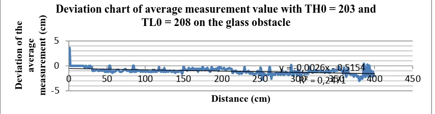
So the best value for TH0 is 203 and TL0 is 208 with the slope value is -0.002. The chart with this value is shown at Figure 2.3. In that Figure the greatest value of deviation of measurement average value is -3 cm at 380 cm of range, with the measurement error average is 0.685%.
Figure 2.3 Deviation chart of average measurement value with TH0 = 203 and
TL0 = 208 on the glass obstacle
Application of compass and range sensors 27
For deviation chart of measurement average value of range using TH0 = 203 and TL0 = 208 on the paint coated wall is shown at Figure 2.4. The slope value of that chart is 0.00004, with the greatest average deviation value is 12 cm at 260 m of range and the deviation value over ±3 cm has been occurred since 358 cm of range with the deviation value is 10.4 cm
Figure 2.4 Deviation chart of average measurement value with TH0 = 203 and
TL0 = 208 on the paint coated wall as obstacle.
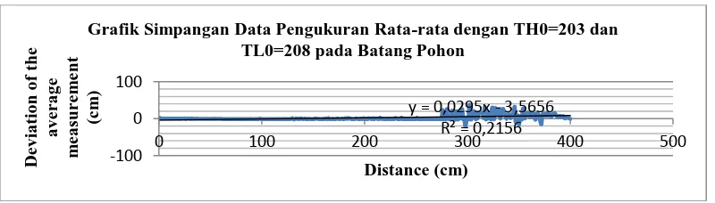
With the same value for TH0 and TL0, then the deviation chart of average measurement value on the trunk of mahogany tree is shown at Figure 2.5. The slope of that chart is 0.029 with the greatest average deviation value is 38,2 cm at 302 of range and the deviation value over ±3 cm has been occurred since 276 cm of range with the deviation value is 23,6 cm
Figure 2.5 Deviation chart of average measurement value with TH0 = 203 and
TL0 = 208 on the trunk of mahogany tree as obstacle.
B. Cardinal direction determination
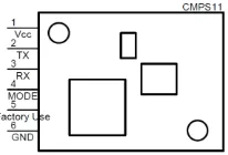
Cardinal direction determination is using CMPS11 as compass sensor, the pin configuration is shown as Figure 2.6.
Deviation chart of average measurement value with TH0 = 203 and TL0 = 208 on the paint coated wall as obstacle.
y = 0,0295x - 3,5656
28 I Gede Surya Adi Pranata et al.
Figure 2.6 Pin Configuration ofCMPS11
In the data acquisition, CMPS11 provide serial communication mode of UART (Universal Asynchronous Receiver Transmitter) with a default baud rate of 9600 bps and data packaging of 2 stop bits without parity. Microcontroller AT89S52 didn’t provide data packaging mode of 2 stop bits, so in this application UART is set into mode 3 with ninth bit of data package (parity bit) is set into constant high, that customizations are do at SCON and SMOD register, so microcontroller AT89S52 do as if it has serial communication protocol of UART with 2 stop bits as shown in Figure 2.7
Figure 2.7 Serial Communication Protocol Setting of AT89S52 at Mode 3 with
Parity Bit is Set
To obtain baud rate value of 9600 bps, timer 1 is set at mode 2 (auto reload). With crystal frequency of 11,0592 MHz, then the value that must be filled into TH1 and TL1 register is;
�� = − �� × � � �
× × −� (2.4)
�� = − × × × �
�� = − × × × � =
Application of compass and range sensors 29
Figure 2.8 Voltage Divider Circuit with 2 1N4007 Diodes and A Resistor
Based on characteristic chart of 1N4007 diodes at datasheet, at specific temperature of 20 °C, the drop voltage of diodes at 25 mA is 0,73 Volt approximately, so the drop voltage at CMPS11 is;
� = � − (� ) = � − , � = , �.
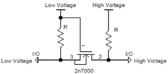
To bridge serial communication level between 3.54 V and 5 V of AT89S52, Level Converter circuit based on FET2N7000 is used that connect TX pin of CMPS11 with RX pin of AT89S52 and RX pin of CMPS11 with TX pin of AT89S52 as shown in Figure 2.9.
Figure 2.9 Level Converter Circuit Based on FET2N7000
Data acquisition from CMP11 is done with sending 0x12h instruction that is data acquisition of 8 bit of data width that represent angle of cardinal direction from 0° to 359,9°. Because of data measurement is agree with circular angle, then angle of 360° is equal to 0° and vice versa, so binary of 0 is equal to 256 and also vice versa. Relation chart of angle of compass (x axis) with average of 8 bit data mode that is produced by CMPS11 on measurement process (y axis) is shown in Figure 2.10
Figure 2.10 Relation Chart Between Angle Of Compass and CMPS11 Outputs y = 0,7107x - 0,9973
30 I Gede Surya Adi Pranata et al.
Comparator value of measurement data that is produced by CMPS11 is determined by equation 2.5
� = � ∙ � − � / � � − � � (2.5)
Then average of deviation measurement value for every measurement of a angle is determined by equation 2.6.
� � �� � � = �̅̅̅ − �� (2.6)
Percent of error of deviation measurement average that is produced by CMPS11 per maximum measurement data value for circular angle is determined by equation 2.7
θmax = Maximum compass angle of cardinal direction (359,9°) θmin = Minimum compass angle of cardinal direction (0°) ��
̅̅̅ = Average of data measurement value
So, error average of all measurement data value that is produced by CMPS11 is 0,43%
C. Output of the supporting tool for blind people mobility as indicator
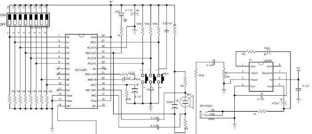
Speech output as indicator for cardinal direction information is produced using chip-corder ISD1420 which can record and playback audio signal for maximum duration is 20 second. On this IC there is address pin that is used for determine recording and playback address of audio signal. There is also control pin such as PlayL, PlayE and REC to give playback or recording instruction to the IC. Based on datasheet of ISD1420, so schematic of ISD1420 circuit can be made as shown in Figure 2.11. LM386 is used to amplify the audio signal from ISD1420 and setting the audio volume.
Figure 2.11 Schematic of ISD1420 circuit as audio recording and playback
Application of compass and range sensors 31
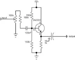
In addition pin address also used for operation mode by setting 2 of MSB into logical high and executed by apply high to low transition to control pin such as PlayE, PlayL or REC pin. Because of that reason, in the audio signal addressing have to avoid 2 of MSB is set to logical high, so the highest address can be used for audio addressing is 10111111 or 191 decimal. Because of maximum duration is 20 second, so duration per bit is 105ms. In this research there is 8 voice with the longest duration is 10 decimal and the shortest duration is 8 decimal as shown in Table 2.1 produced by microcontroller AT89S52 immediately by flipping level of P2.1 pin frequently at certain period. In this matter, timer 0 is used for time references. So at sub-program of timer 0 interruption, there is 2 different routine because of timer 0 also used for time measurement of PWM pulse that is produced by HC-SR04. Therefore a flag is made in that sub-program to select routine that will be performed. For the next step, pulse output from P2.1 is amplified by audio power amplifier circuit based on transistor 2N2222 with the schematic is shown in Figure 2.12
Figure 2.12 Audio Power Amplifier Circuit Based On Transistor 2N2222
D. Schematic of mobility supporting tool circuit for blind people
32 I Gede Surya Adi Pranata et al.
Figure 2.13 Overall schematic of mobility supporting tool circuit for blind people
E. Put the trial to blind people
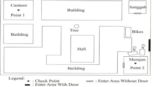
The trial to blind people is done as much as 15 times for 15 different blind people, with the route that has 2 check points as shown in figure 2.14
Figure 2.14 Lay out of the trial location
From 15 blind people there is 11 people who success in reaching both check point by support of a cane whereas by additional support of range sensor and compass sensor which applied to eyeglass as supporting tool there is 12 success blind people in reaching both check point. So percent of successfulness of this tool for helping blind people to reach the check point is 80%.
3.
Conclusion
Application of compass and range sensors 33
best value for TH0 and TL0 in PWM pulse measurement of HC-SR04 using AT89S52 with 11.0592 MHz of crystal frequency is 203 and 208 respectively. From 3 different obstacles which is used in this research, the most stable of range measurement is happen on the glass obstacles with the maximum average deviation is -3 cm up to 400 cm of range, and the worst stability of range measurement is happen on the trunk of mahogany tree as obstacles with the average deviation of more than ±3 cm has been occurred since 276 cm of range with the number of deviation is 23.6 cm. Cardinal direction measurement by CMPS11 has error average value of 0.43%
References
[1] S. Al-Fedaghi and N. Aljallal, Conceptual schematization of microcontroller and assembly language, International Journal of Software Engineering and Its Applications, 8 (2014), no. 10, 179 - 190.
[2] Amjed S. Al-Fahoum, Heba B. Al-Hmoud, Ausaila A. Al-Fraihat, A smart infrared microcontroller-based blind guidance system, Active and Passive Electronic Components, 2013 (2013), Article ID 726480, 1 - 7.
http://dx.doi.org/10.1155/2013/726480
[3] M.V. Kumar and S. Angadi, Study of Uart Transmitter in Microcontroller,
International Journal of Engineering and Advanced Technology (IJEAT), 2 (2012), no. 2, 155 - 158.
[4] M. Bousbia-Salah, M. Fezari, A navigation Tool for Blind People, Innovation and Advance Techniques in Computer and Information Science and Engineering, Springer, 2007, 333 - 337.
http://dx.doi.org/10.1007/978-1-4020-6268-1_59
[5] E. van der Heijden, P.P.L. Regtien, Wearable navigation assistance – a tool for the blind, MEASUREMENT SCIENCE REVIEW, 5 (2005), sect. 2, no. 2, 53 - 56.
[6] B. Kahanwal, Abstraction level taxonomy of programming language frameworks, International Journal of Programming Language and Applications (IJPLA), 3 (2013), no. 4, 1 - 12.
http://dx.doi.org/10.5121/ijpla.2013.3401
[7] S. Mahall, H. Lokhande, Ultrasonic Spectacles & Waist- Belt for Visually Impaired & Blind Person, IOSR Journal of Engineering (IOSERJEN), 4 (2014), 46 - 49. http://dx.doi.org/10.9790/3021-04234649
34 I Gede Surya Adi Pranata et al.
[9] Sidek, A.A. Mutalib, Smart cane: assistive cane for visually-impaired people,
IJCSI International Journal of Computer Science Issues, 8 (2011), 21 - 27.
[10] P.T. Rajan, K.K. Jithin, K.S. Hareesh, C.A. Habeeburahman, A. Jithin, Range detection based on ultrasonic principle, International Journal of Advanced Research in Electrical, Electronics and Instrumentation Engineering (IJAREEIE), 3 (2014), no. 2, 7638 - 7642.
[11] Robert-Bela Nagy, F. Popentiu, R.C. Tarca, Accuracy measurement of the national instrument starter Kit 2.0’S Ping))) Ultrasonic Sensor, Annals of The Oradea University, 1 (2015), 263 - 268.