Note from the Publisher
This book has been compiled using extracts from the following books within the range of Automotive Engineering books in the Elsevier collection:
Blundell, M and Harty, D. (2004)The Multibody Systems Approach to Vehicle Dynamics, 9780750651127
Brown, J., Robertson, A.J. and Serpento, S. (2001)Motor Vehicle Structures, 9780750651349
Davies, G. (2003) Materials for Automobile Bodies, 9780750656924
Fenton, J. and Hodkinson, R. (2001)Lightweight Electric/ Hybrid Vehicle Design, 9780750650922
Garrett, T.K., Newton, K. and Steels, W. (2000) The Motor Vehicle 13e, 9780750644495
Happian-Smith, J (2001)Introduction to Modern Vehicle Design, 9780750661294
Heisler, H. (1998) Vehicle and Engine Technology, 9780340691861
Martyr, A.J. and Plint, M.A. (2007) Engine Testing 3e, 9780750684392
Pacejka, H. (2005) Tyre and Vehicle Dynamics, 9780750669184
Reimpell, J., Stoll, H. and Betzler, J. (2001)Automotive Chassis: Engineering Principles, 9780750650540
Ribbens, W. (2003)Understanding Automotive Electron-ics, 9780750675994
Vlacic, L. and Parent, M. (2001)Intelligent Vehicle Tech-nologies, 9780750650939
The extracts have been taken directly from the above source books, with some small editorial changes. These changes have entailed the re-numbering of Sections and Figures. In view of the breadth of content and style of the source books, there is some overlap and repetition of material between chapters and significant differences in style, but these features have been left in order to retain the flavour and readability of the individual chapters.
Units of measure
Units are provided in either SI or IP units. A conversion table for these units is provided at the front of the book.
Upgrade to an Electronic Version
An electronic version of Automotive Engineering, the Automotive Engineering e-Mega Reference, 9781856175784 A fully searchable Mega Reference eBook, providing all
the essential material needed by Automotive Engineers on a day-to-day basis.
Fundamentals, key techniques, engineering best practice and rules-of-thumb at one quick click of a button
Over 1,500 pages of reference material, including over 1,000 pages not included in the print edition
Automotive
Engineering
Powertrain, Chassis System and Vehicle Body
Edited by David A. Crolla
Amsterdam$Boston$Heidelberg$London$New York$Oxford Paris$San Diego$San Francisco$Sydney$Tokyo
Butterworth-Heinemann is an imprint of Elsevier Linacre House, Jordan Hill, Oxford OX2 8DP, UK
30 Corporate Drive, Suite 400, Burlington, MA 01803, USA
First edition 2009
Copyright2009 Elsevier Inc. All rights reserved
No part of this publication may be reproduced, stored in a retrieval system or transmitted in any form or by any means electronic, mechanical, photocopying, recording or otherwise without the prior written permission of the publisher
Permissions may be sought directly from Elsevier’s Science & Technology Rights Department in Oxford, UK: phone (+44) (0) 1865 843830; fax (+44) (0) 1865 853333; email:[email protected]. Alternatively visit the Science and Technology website at
www.elsevierdirect.com/rightsfor further information
Notice
No responsibility is assumed by the publisher for any injury and/or damage to persons or property as a matter of products liability, negligence or otherwise, or from any use or operation of any methods, products, instructions or ideas contained in the material herein. Because of rapid advances in the medical sciences, in particular, independent verification of diagnoses and drug dosages should be made
British Library Cataloguing in Publication Data
A catalogue record for this book is available from the British Library
Library of Congress Cataloguing-in-Publication Data
A catalog record for this book is available from the Library of Congress
ISBN: 978-1-85617-577-7
For information on all Butterworth-Heinemann publications visit our web site atelsevierdirect.com
Printed and bound in the United States of America
Contents
Section 1 INTRODUCTION TO ENGINE DESIGN . . . 1
1.1 Piston-engines cycles of operation . . . 3
Section 2 ENGINE TESTING . . . 19
2.1 Measurement of torque, power, speed and fuel consumption; acceptance and type tests, accuracy of the measurements . . . 21
Section 3 ENGINE EMISSIONS . . . 51
3.1 Emissions control . . . 53
Section 4 DIGITAL ENGINE CONTROL . . . 75
4.1 Digital engine control systems . . . 77
Section 5 TRANSMISSIONS . . . 105
5.1 Transmissions and driveline . . . 107
Section 6 ELECTRIC VEHICLES . . . 141
6.1 Battery/fuel-cell EV design packages . . . 143
Section 7 HYBRID VEHICLES . . . 173
7.1 Hybrid vehicle design . . . 175
Section 8 SUSPENSIONS . . . 203
8.1 Types of suspension and drive . . . 205
Section 9 STEERING . . . 255
9.1 Steering . . . 257
Section 10 TYRES . . . 283
10.1 Tyres and wheels . . . 285
Section 11 HANDLING . . . 323
11.1 Tyre characteristics and vehicle handling and stability . . . 325
Section 12 BRAKES . . . 359
12.1 Braking systems . . . 361
Section 13 VEHICLE CONTROL SYSTEMS . . . 391
13.1 Vehicle motion control . . . 393
Section 14 INTELLIGENT TRANSPORT SYSTEMS . . . 417
14.1 Global positioning technology . . . 419
14.2 Decisional architecture . . . 437
Section 15 VEHICLE MODELLING . . . 473
15.1 Modelling and assembly of the full vehicle . . . 475
Section 16 STRUCTURAL DESIGN . . . 525
16.1 Terminology and overview of vehicle structure types . . . 527
16.2 Standard sedan (saloon) – baseline load paths . . . 542
Section 17 VEHICLE SAFETY . . . 567
17.1 Vehicle safety . . . 569
Section 18 MATERIALS . . . 591
18.1 Design and material utilization . . . 593
18.2 Materials for consideration and use in automotive body structures . . . 632
Section 19 AERODYNAMICS . . . 661
19.1 Body design: aerodynamics . . . 663
Section 20 REFINEMENT . . . 673
20.1 Vehicle refinement: purpose and targets . . . 675
Section 21 INTERIOR NOISE . . . 685
21.1 Interior noise: assessment and control . . . 687
Section 22 EXTERIOR NOISE . . . 737
22.1 Exterior noise: assessment and control . . . 739
Section 23 INSTRUMENTATION AND TELEMATICS . . . 783
23.1 Automotive instrumentation and telematics . . . 785
Index . . . 809 C O N T E N T S
Section
One
Introduction to engine design
Section
One
Section
One
Section
One
Section
One
Section
One
1.1
Chapter
1.1
Piston-engine cycles
of operation
Heinz Heisler
1.1.1 The internal-combustion
engine
The piston engine is known as an internal-combustion heat-engine. The concept of the piston engine is that a supply of air-and-fuel mixture is fed to the inside of the cylinder where it is compressed and then burnt. This internal combustion releases heat energy which is then converted into useful mechanical work as the high gas pressures generated force the piston to move along its stroke in the cylinder. It can be said, therefore, that a heat-engine is merely an energy transformer.
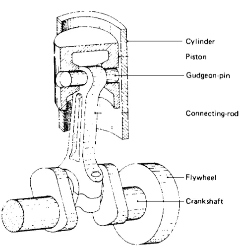
To enable the piston movement to be harnessed, the driving thrust on the piston is transmitted by means of a connecting-rod to a crankshaft whose function is to convert the linear piston motion in the cylinder to a rotary crankshaft movement (Fig. 1.1-1). The piston can thus be made to repeat its movement to and fro, due to the constraints of the crankshaft crankpin’s circular path and the guiding cylinder.
The backward-and-forward displacement of the piston is generally referred to as thereciprocatingmotion of the piston, so these power units are also known as reciprocating engines.
1.1.1.1 Engine components and terms
The main problem in understanding the construction of the reciprocating piston engine is being able to identify and name the various parts making up the power unit. To this end, the following briefly describes the major components and the names given to them (Figs. 1.1-1 and 1.1-2).
Cylinder block This is a cast structure with cylin-drical holes bored to guide and support the pistons and to
harness the working gases. It also provides a jacket to contain a liquid coolant.
Cylinder head This casting encloses the combus-tion end of the cylinder block and houses both the inlet and exhaust poppet-valves and their ports to admit air– fuel mixture and to exhaust the combustion products.
Crankcase This is a cast rigid structure which sup-ports and houses the crankshaft and bearings. It is usually cast as a mono-construction with the cylinder block.
Sump This is a pressed-steel or cast-aluminium-alloy container which encloses the bottom of the crank-case and provides a reservoir for the engine’s lubricant. Fig. 1.1-1 Pictorial view of the basic engine.
Vehicle and Engine Technology, ISBN: 9780340691861
Piston This is a pressure-tight cylindrical plunger which is subjected to the expanding gas pressure. Its function is to convert the gas pressure from combustion into a concentrated driving thrust along the connecting-rod. It must therefore also act as a guide for the small-end of the connecting-rod.
Piston rings These are circular rings which seal the gaps made between the piston and the cylinder, their object being to prevent gas escaping and to control the amount of lubricant which is allowed to reach the top of the cylinder.
Gudgeon-pin This pin transfers the thrust from the piston to the connecting-rod small-end while permitting the rod to rock to and fro as the crankshaft rotates.
Connecting-rod This acts as both a strut and a tie link-rod. It transmits the linear pressure impulses acting on the piston to the crankshaft big-end journal, where they are converted into turning-effort.
Crankshaft A simple crankshaft consists of a cir-cular-sectioned shaft which is bent or cranked to form two perpendicular crank-arms and an offset big-end journal. The unbent part of the shaft provides the main journals. The crankshaft is indirectly linked by the connecting-rod to the piston – this enables the straight-line motion of the piston to be transformed into a rotary motion at the crankshaft about the main-journal axis.
Crankshaft journals These are highly finished cy-lindrical pins machined parallel on both the centre axes and the offset axes of the crankshaft. When assembled, these journals rotate in plain bush-type bearings mounted in the crankcase (the main journals) and in one end of the connecting-rod (the big-end journal).
Small-end This refers to the hinged joint made by the gudgeon-pin between the piston and the connecting-rod
so that the connecting-rod is free to oscillate relative to the cylinder axis as it moves to and fro in the cylinder.
Big-end This refers to the joint between the connecting-rod and the crankshaft big-end journal which provides the relative angular movement between the two components as the engine rotates.
Main-ends This refers to the rubbing pairs formed between the crankshaft main journals and their re-spective plain bearings mounted in the crankcase.
Line of stroke The centre path the piston is forced to follow due to the constraints of the cylinder is known as the line of stroke.
Inner and outer dead centres When the crankarm and the connecting-rod are aligned along the line of stroke, the piston will be in either one of its two ex-treme positions. If the piston is at its closest position to the cylinder head, the crank and piston are said to be at inner dead centre (IDC) or top dead centre (TDC). With the piston at its furthest position from the cyl-inder head, the crank and piston are said to be at outer dead centre (ODC) or bottom dead centre (BDC). These reference points are of considerable importance for valve-to-crankshaft timing and for either ignition or injection settings.
Clearance volume The space between the cylinder head and the piston crown at TDC is known as the clearance volume or the combustion-chamber space.
Crank-throw The distance from the centre of the crankshaft main journal to the centre of the big-end journal is known as the crank-throw. This radial length influences the leverage the gas pressure acting on the piston can apply in rotating the crankshaft.
Piston stroke The piston movement from IDC to ODC is known as the piston stroke and corresponds Fig. 1.1-2 Sectional view of the basic engine.
4
to the crankshaft rotating half a revolution or 180. It is also equal to twice the crank-throw.
i.e. L¼2R
where L¼piston stroke
and R¼crank-throw
Thus a long or short stroke will enable a large or small turning-effort to be applied to the crankshaft respectively.
Cylinder bore The cylinder block is initially cast with sand cores occupying the cylinder spaces. After the sand cores have been removed, the rough holes are ma-chined with a single-point cutting tool attached radially at the end of a rotating bar. The removal of the unwanted metal in the hole is commonly known as boring the cyl-inder to size. Thus the finished cylindrical hole is known as the cylinder bore, and its internal diameter simply as the bore or bore size.
1.1.1.2 The four-stroke-cycle
spark-ignition (petrol) engine
The first internal-combustion engine to operate suc-cessfully on the four-stroke cycle used gas as a fuel and was built in 1876 by Nicolaus August Otto, a self-taught German engineer at the Gas-motoreufabrik Deutz factory near Cologne, for many years the largest manu-facturer of internal-combustion engines in the world. It was one of Otto’s associates – Gottlieb Daimler – who later developed an engine to run on petrol which was described in patent number 4315 of 1885. He also pioneered its application to the motor vehicle (Fig. 1.1-3).
Petrol engines take in a flammable mixture of air and petrol which is ignited by a timed spark when the charge is compressed. These engines are therefore sometimes called spark-ignition (S.I.) engines.
These engines require four piston strokes to complete one cycle: an air-and-fuel intake stroke moving outward from the cylinder head, an inward movement towards the cylinder head compressing the charge, an outward power stroke, and an inward exhaust stroke.
Induction stroke (Fig. 1.1-3(a)) The inlet valve is opened and the exhaust valve is closed. The piston descends, moving away from the cylinder head (Fig. 1.1-3(a)). The speed of the piston moving along the cylinder creates a pressure reduction or depression which reaches a maximum of about 0.3 bar below at-mospheric pressure at one-third from the beginning of the stroke. The depression actually generated will depend on the speed and load experienced by the engine, but a typical average value might be 0.12 bar below atmospheric pressure. This depression induces (sucks in) a fresh charge of air and atomised petrol in
proportions ranging from 10 to 17 parts of air to one part of petrol by weight.
An engine which induces fresh charge by means of a depression in the cylinder is said to be ‘normally aspi-rated’ or ‘naturally aspiaspi-rated’.
Compression stroke(Fig. 1.1-3(b)) Both the inlet and the exhaust valves are closed. The piston begins to ascend towards the cylinder head (Fig. 1.1-3(b)). The induced air-and-petrol charge is progressively com-pressed to something of the order of eighth to one-tenth of the cylinder’s original volume at the piston’s innermost position. This compression squeezes the air and atomised-petrol molecules closer together and not only increases the charge pressure in the cylinder but also raises the temperature. Typical maximum cylinder compression pressures will range between 8 and 14 bar with the throttle open and the engine running under load.
Power stroke(Fig. 1.1-3(c)) Both the inlet and the exhaust valves are closed and, just before the piston ap-proaches the top of its stroke during compression, a spark-plug ignites the dense combustible charge (Fig. 1.1-3(c)). By the time the piston reaches the in-nermost point of its stroke, the charge mixture begins to burn, generates heat, and rapidly raises the pressure in the cylinder until the gas forces exceed the resisting load. The burning gases then expand and so change the piston’s direction of motion and push it to its outermost position. The cylinder pressure then drops from a peak value of about 60 bar under full load down to maybe 4 bar near the outermost movement of the piston.
Exhaust stroke (Fig. 1.1-3(d)) At the end of the power stroke the inlet valve remains closed but the ex-haust valve is opened. The piston changes its direction of motion and now moves from the outermost to the in-nermost position (Fig. 1.1-3(d)). Most of the burnt gases will be expelled by the existing pressure energy of the gas, but the returning piston will push the last of the spent gases out of the cylinder through the exhaust-valve port and to the atmosphere.
During the exhaust stroke, the gas pressure in the cylinder will fall from the exhaust-valve opening pressure (which may vary from 2 to 5 bar, depending on the engine speed and the throttle-opening position) to atmospheric pressure or even less as the piston nears the innermost position towards the cylinder head.
Cycle of events in a four-cylinder engine (Figs. 1.1-3(e)–(g)) Fig. 1.1-3(e)illustrates how the cycle of events – induction, compression, power, and exhaust – is phased in a four-cylinder engine. The relationship between cylinder pressure and piston stroke position over the four strokes is clearly shown inFigs. 1.1-3(f) and (g) and, by following the arrows, it can be seen that a figures of eight is repeatedly being traced.
1.1.1.3 Valve timing diagrams
In practice, the events of the four-stroke cycle do not start and finish exactly at the two ends of the strokes – to improve the breathing and exhausting, the inlet valve is arranged to open before TDC and to close after BDC and
the exhaust valve opens before BDC and closes after TDC. These early and late opening and closing events can be shown on a valve timing diagram such asFig. 1.1-4.
Valve lead This is where a valve opens so many degrees of crankshaft rotation before either TDC or BDC.
Fig. 1.1-3 Four-stroke-cycle petrol engine.
6
Valve lag This is where a valve closes so many de-grees of crankshaft rotation after TDC or BDC.
Valve overlap This is the condition when both the inlet and the exhaust valves are open at the same time during so many degrees of crankshaft rotation.
1.1.2 The two-stroke-cycle petrol
engine
The first successful design of a three-port two-stroke engine was patented in 1889 by Joseph Day & Son of Bath. This employed the underside of the piston in conjunction with a sealed crank-case to form a scavenge pump (‘scavenging’ being the pushing-out of exhaust gas by the induction of fresh charge) (Fig. 1.1-5).
This engine completes the cycle of events – induction, compression, power, and exhaust – in one revolution of the crankshaft or two complete piston strokes.
Crankcase-to-cylinder mixture transfer(Fig. 1.1-5(a)) The piston moves down the cylinder and initially uncovers the exhaust port (E), releasing the burnt exhaust gases to the atmosphere. Simultaneously the downward move-ment of the underside of the piston compresses the pre-viously filled mixture of air and atomised petrol in the crankcase (Fig. 1.1-5(a)). Further outward movement of the piston will uncover the transfer port (T), and the compressed mixture in the crankcase will then be trans-ferred to the combustion-chamber side of the cylinder. The situation in the cylinder will then be such that the fresh charge entering the cylinder will push out any remaining burnt products of combustion – this process is generally referred to as cross-flow scavenging.
Cylinder compression and crankcase induction (Fig. 1.1-5(b)) The crankshaft rotates, moving the piston in the direction of the cylinder head. Initially the
piston seals off the transfer port, and then a short time later the exhaust port will be completely closed. Further inward movement of the piston will compress the mix-ture of air and atomised petrol to about one-seventh to one-eighth of its original volume (Fig. 1.1-5(b)).
At the same time as the fresh charge is being com-pressed between the combustion chamber and the piston head, the inward movement of the piston increases the total volume in the crank-case so that a depression is created in this space. About half-way up the cylinder stroke, the lower part of the piston skirt will uncover the inlet port (I), and a fresh mixture of air and petrol pre-pared by the carburettor will be induced into the crank-case chamber (Fig. 1.1-5(b)).
Cylinder combustion and crankcase compression (Fig. 1.1-5(c)) Just before the piston reaches the top of its stroke, a spark-plug situated in the centre of the cylinder head will be timed to spark and ignite the dense mixture. The burning rate of the charge will rapidly raise the gas pressure to a maximum of about 50 bar under full load. The burning mixture then expands, forcing the piston back along its stroke with a corresponding reduction in cylinder pressure (Fig. 1.1-5(c)).
Considering the condition underneath the piston in the crankcase, with the piston initially at the top of its stroke, fresh mixture will have entered the crankcase through the inlet port. As the piston moves down its stroke, the piston skirt will cover the inlet port, and any further downward movement will compress the mixture in the crankcase in preparation for the next charge transfer into the cylinder and combustion-chamber space (Fig. 1.1-5(c)).
The combined cycle of events adapted to a three-cylinder engine is shown inFig. 1.1-5(d).Figs. 1.1-5(e) and (f)show the complete cycle in terms of opening and closing events and cylinder volume and pressure changes respectively.
1.1.2.1 Reverse-flow (Schnuerle)
scavenging
To improve scavenging efficiency, a loop-scavenging system which became known as the reverse-flow or (after its inventor, Dr E. Schnuerle) as the Schnuerle scaveng-ing system was developed (Fig. 1.1-6). This layout has a transfer port on each side of the exhaust port, and these direct the scavenging charge mixture in a practically tangential direction towards the opposite cylinder wall. The two separate columns of the scavenging mixture meet and merge together at this wall to form one inward rising flow which turns under the cylinder head and then flows down on the entry side, thus forming a complete loop. With this form of porting, turbulence and inter-mixing of fresh fuel mixture with residual burnt gases will be minimal over a wide range of piston speeds. Fig. 1.1-4 Valve timing diagram.
Note that in this particular design the charge mixture is transferred through ports formed in the piston skirt. Al-ternatively, extended transfer passages may be preferred so that the piston skirt plays no part in the timed transfer.
1.1.2.2 Crankcase disc-valve and
reed-valve inlet charge control
An alternative to the piston-operated crankcase inlet port is to use a disc-valve attached to and driven by the crankshaft (Fig. 1.1-7(a)). This disc-valve is timed to
open and close so that the fresh charge is induced to enter the crankcase as early as possible, and only at the point when the charge is about to be transferred into the cylinder is it closed. This method of controlling crankcase induction does not depend upon the piston displacement to uncover the port – it can therefore be so phased as to extend the filling period (Fig. 1.1-7).
A further method of improving crankcase filling is the use of reed-valves (Fig. 1.1-7(b)). These valves are not timed to open and close, but operate automatically when the pressure difference between the crankcase and the air intake is sufficient to deflect the reed-spring. In other Fig. 1.1-5 Two-stroke-cycle petrol engine.
8
words, these valves sense the requirements of the crankcase and so adjust their opening and closing fre-quencies to match the demands of the engine.
1.1.2.3 Comparison of two- and
four-stroke-cycle petrol engines
The following remarks compare the main points re-garding the effectiveness of both engine cycles.
a) The two-stroke engine completes one cycle of events for every revolution of the crankshaft, com-pared with the two revolutions required for the four-stroke engine cycle.
b)Theoretically, the two-stroke engine should develop twice the power compared to a four-stroke engine of the same cylinder capacity.
c) In practice, the two-stroke engine’s expelling of the exhaust gases and filling of the cylinder with fresh mixture brought in through the crankcase is far less effective than having separate exhaust and induction strokes. Thus the mean effective cylin-der pressures in two-stroke units are far lower than in equivalent four-stroke engines.
d)With a power stroke every revolution instead of every second revolution, the two-stroke engine
will run smoother than the four-stroke power unit for the same size of flywheel.
e)Unlike the four-stroke engine, the two-stroke engine does not have the luxury of separate ex-haust and induction strokes to cool both the cylin-der and the piston between power strokes. There is therefore a tendency for the piston and small-end to overheat under heavy driving conditions.
f)Due to its inferior scavenging process, the two-stroke engine can suffer from the following:
i)inadequate transfer of fresh mixture into the cylinder,
ii)excessively large amounts of residual exhaust gas remaining in the cylinder,
Fig. 1.1-6 Reverse flow or Schnuerle scavenging.
Fig. 1.1-7 Crankcase disc-valve and reed-valve induction.
iii)direct expulsion of fresh charge through the exhaust port.
These undesirable conditions may occur under dif-ferent speed and load situations, which greatly influences both power and fuel consumption.
g)Far less maintenance is expected with the two-stroke engine compared with the four-two-stroke engine, but there can be a problem with the prod-ucts of combustion carburising at the inlet, transfer, and exhaust ports.
h)Lubrication of the two-stroke engine is achieved by mixing small quantities of oil with petrol in pro-portions anywhere between 1:16 and 1:24 so that, when crankcase induction takes place, the various rotating and reciprocating components will be lubricated by a petroil-mixture mist. Clearly a continuous proportion of oil will be burnt in the cylinder and expelled into the atmosphere to add to unwanted exhaust emission.
i)There are fewer working parts in a two-stroke engine than in a four-stroke engine, so two-stroke engines are generally cheaper to manufacture.
1.1.3 Four-stroke-cycle
compression-ignition (diesel) engine
Compression-ignition (C.I.) engines burn fuel oil which is injected into the combustion chamber when the air charge is fully compressed. Burning occurs when the compression temperature of the air is high enough to spontaneously ignite the finely atomised liquid fuel. In other words, burning is initiated by the self-generated heat of compression (Fig. 1.1-8).
Engines adopting this method of introducing and mixing the liquid fuel followed by self-ignition are also referred to as ‘oil engines’, due to the class of fuel burnt, or as ‘diesel engines’ after Rudolf Diesel, one of the many inventors and pioneers of the early C.I. engine. Note: in the United Kingdom fuel oil is known as ‘DERV’, which is the abbreviation of ‘diesel-engine road vehicle’.
Just like the four-stroke-cycle petrol engine, the C.I. engine completes one cycle of events in two crankshaft revolutions or four piston strokes. The four phases of these strokes are (i) induction of fresh air, (ii) com-pression and heating of this air, (iii) injection of fuel and its burning and expansion, and (iv) expulsion of the products of combustion.
Induction stroke (Fig. 1.1-8(a)) With the inlet valve open and the exhaust valve closed, the piston moves away from the cylinder head (Fig. 1.1-8(a)).
The outward movement of the piston will establish a depression in the cylinder, its magnitude depending on
the ratio of the cross-sectional areas of the cylinder and the inlet port and on the speed at which the piston is moving. The pressure difference established between the inside and outside of the cylinder will induce air at atmospheric pressure to enter and fill up the cylinder. Unlike the petrol engine, which requires a charge of air-and-petrol mixture to be drawn past a throttle valve, in the diesel-engine inlet system no restriction is necessary and only pure air is induced into the cylinder. A maxi-mum depression of maybe 0.15 bar below atmospheric pressure will occur at about one-third of the distance along the piston’s outward stroke, while the overall average pressure in the cylinder might be 0.1 bar or even less.
Compression stroke(Fig. 1.1-8(b)) With both the inlet and the exhaust valves closed, the piston moves towards the cylinder head (Fig. 1.1-8(b)).
The air enclosed in the cylinder will be compressed into a much smaller space of anything from 1/12 to 1/24 of its original volume. A typical ratio of maximum to minimum air-charge volume in the cylinder would be 16:1, but this largely depends on engine size and designed speed range.
During the compression stroke, the air charge initially at atmospheric pressure and temperature is reduced in volume until the cylinder pressure is raised to between 30 and 50 bar. This compression of the air generates heat which will increase the charge temperature to at least 600C under normal running conditions.
Power stroke (Fig. 1.1-8(c)) With both the inlet and the exhaust valves closed and the piston almost at the end of the compression stroke (Fig. 1.1-8(c)), diesel fuel oil is injected into the dense and heated air as a high-pressure spray of fine particles. Provided that they are properly atomised and distributed throughout the air charge, the heat of compression will then quickly vaporise and ignite the tiny droplets of liquid fuel. Within a very short time, the piston will have reached its innermost position and extensive burning then releases heat energy which is rapidly converted into pressure energy. Expansion then follows, pushing the piston away from the cylinder head, and the linear thrust acting on the piston end of the connecting-rod will then be changed to rotary movement of the crankshaft.
Exhaust stroke When the burning of the charge is near completion and the piston has reached the out-ermost position, the exhaust valve is opened. The piston then reverses its direction of motion and moves towards the cylinder head (Fig. 1.1-8(d)).
The sudden opening of the exhaust valve towards the end of the power stroke will release the still burning products of combustion to the atmosphere. The pressure energy of the gases at this point will accelerate their expulsion from the cylinder, and only towards the end of
10
the piston’s return stroke will the piston actually catch up with the tail-end of the outgoing gases.
Fig. 1.1-8(e) illustrates the sequence of the four op-erating strokes as applied to a four-cylinder engine, and the combined operating events expressed in terms of cylinder pressure and piston displacement are shown in Figs. 1.1-8(f) and (g).
1.1.3.1 Historical background to the
C.I. engine
Credit for the origination of the C.I. engine is contro-versial, as eminent engineers cannot agree amongst themselves as to which of the patents by Herbert Akroyd-Stuart or Rudolf Diesel contributed most to the Fig. 1.1-8 Four-stroke-cycle diesel engine.
instigation and evolution of the high-speed C.I. engine burning heavy fuel oil. A brief summary of the back-ground and achievements of these two pioneers is as follows.
Herbert Akroyd-Stuart, born 1864, was trained as an engineer in his father’s works at Fenny Stratford, England. Between 1885 and 1890 he took out several patents for improvements to oil engines, and later, in conjunction with a Charles R. Binney of London, he took out patent number 7146 of 1890 describing the operation of his engine. Air alone was drawn into the cylinder and com-pressed into a separate combustion chamber (known as the vaporiser) through a contracted passage or bottle-neck. A liquid fuel spray was then injected into the compressed air near the end of the compression stroke by means of a pump and a spraying nozzle. The combination of the hot chamber and the rise in temperature of the compressed air provided automatic ignition and rapid combustion at nearly constant volume – a feature of the C.I. engines of today.
These early engines were of low compression, the explosion taking place mainly due to the heat of the vaporiser chamber itself so that these engines became known as ‘hot-bulb’ or ‘surface-ignition’ engines. At starting, the separate combustion chamber was heated externally by an oil-lamp until the temperature attained was sufficient to ignite a few charges by compression. Then the chamber was maintained at a high enough temperature by the heat retained from the explosion together with the heat of the compressed air.
Rudolf Diesel was born in Paris in 1858, of German parents, and was educated at Augsburg and Munich. His works training was with Gebru¨-der Sulzer in Winterthur. Dr Diesel’s first English patent, number 7421, was dated 1892 and was for an engine working on the ideal Carnot cycle and burning all kinds of fuel – solid, liquid, and gas – but the practical difficulties of achieving this ther-modynamic cycle proved to be far too much. A reliable diesel oil engine was built in 1897 after four years of experimental work in the Mashinen-fabrik Augsburg Nu¨rnberg (MAN) workshops.
In this engine, air was drawn into the cylinder and was compressed to 35–40 bar. Towards the end of the com-pression stroke, an air blast was introduced into the combustion space at a much higher pressure, about 68–70 bar, thus causing turbulence in the combustion chamber. A three-stage compressor driven by the engine (and consuming about 10% of the engine’s gross power) supplied compressed air which was stored in a reservoir. This compressed air served both for starting the engine and for air-injection into the compressed air already in the cylinder – that is, for blasting air to atomise the oil fuel by forcing it through perforated discs fitted around a fluted needle-valve injector. The resulting finely divided oil mist ignites at once when it contacts the hot
compressed cylinder air, and the burning rate then tends to match the increasing cylinder volume as the piston moves outwards – expansion will therefore take place at something approaching constant pressure.
A summary of the combustion processes of Akroyd-Stuart and Diesel is that the former inventor used a low compression-ratio, employed airless liquid-fuel injection, and relied on the hot combustion chamber to vaporise and ignite the fuel; whereas Diesel employed a relatively high compression-ratio, adopted air-injection to atomise the fuel, and made the hot turbulent air initiate burning. It may be said that the modern high-speed C.I. engine em-braces both approaches in producing sparkless automatic combustion – combustion taking place with a combined process of constant volume and constant pressure known as either the mixed or the dual cycle.
1.1.4 Two-stroke-cycle diesel
engine
The pump scavenge two-stroke-cycle engine designed by Sir Dugald Clerk in 1879 was the first successful two-stroke engine; thus the two-two-stroke-cycle engine is sometimes called the Clerk engine. Uniflow scavenging took place – fresh charge entering the combustion chamber above the piston while the exhaust outflow occurred through ports uncovered by the piston at its outermost position.
Low- and medium-speed two-stroke marine diesels still use this system, but high-speed two-stroke diesels reverse the scavenging flow by blowing fresh charge through the bottom inlet ports, sweeping up through the cylinder and out of the exhaust ports in the cylinder head (Fig. 1.1-9(a)).
With the two-stroke-cycle engine, intake and exhaust phases take place during part of the compression and power stroke respectively, so that a cycle of operation is completed in one crankshaft revolution or two piston strokes. Since there are no separate intake and exhaust strokes, a blower is necessary to pump air into the cylinder for expelling the exhaust gases and to supply the cylinder with fresh air for combustion.
Scavenging (induction and exhaust) phase (Fig. 1.1-9(a)) The piston moves away from the cylinder head and, when it is about half-way down its stroke, the exhaust valves open. This allows the burnt gases to escape into the atmosphere. Near the end of the power stroke, a horizontal row of inlet air ports is uncovered by the piston lands (Fig. 1.1-9(a)). These ports admit pressur-ised air from the blower into the cylinder. The space above the piston is immediately filled with air, which now blows up the cylinder towards the exhaust valves in the cylinder head. The last remaining exhaust gases will thus be forced out of the cylinder into the exhaust system. This process
12
of fresh air coming into the cylinder and pushing out unwanted burnt gas is known as scavenging.
Compression phase (Fig. 1.1-9(b)) Towards the end of the power stroke, the inlet ports will be un-covered. The piston then reaches its outermost position and reverses its direction of motion. The piston now moves upwards so that the piston seals and closes the
inlet air ports, and just a little later the exhaust valves close. Any further upward movement will now compress the trapped air (Fig. 1.1-9(b)). This air charge is now reduced to about 1/15 to 1/18 of its original volume as the piston reaches the innermost position. This change in volume corresponds to a maximum cylinder pressure of about 30–40 bar.
Fig. 1.1-9 Two-stroke-cycle diesel engine.
Power phase (Fig. 1.1-9(c)) Shortly before the piston reaches the innermost position to the cylinder head on its upward compression stroke, highly pressur-ised liquid fuel is sprayed into the dense intensely heated air charge (Fig. 1.1-9(c)). Within a very short period of time, the injected fuel droplets will vaporise and ignite, and rapid burning will be established by the time the piston is at the top of its stroke. The heat liberated from the charge will be converted mainly into gas-pressure energy which will expand the gas and so do useful work in driving the piston outwards.
An overall view of the various phases of operation in a two-stroke-cycle three-cylinder diesel engine is shown in Figs. 1.1-9(d), and Figs. 1.1-9(e) and (f) show the cycle of events in one crankshaft revolution expressed in terms of piston displacement and cylinder pressure.
1.1.4.1 Comparison of two- and
four-stroke-cycle diesel engines
A brief but critical comparison of the merits and limi-tations of the two-stroke-cycle diesel engine compared with the four-stroke power unit is made below.
a)Theoretically, almost twice the power can be devel-oped with a two-stroke engine compared with a four-stroke engine.
b)A comparison between a typical 12 litre four-stroke engine and a 7 litre two-stroke engine having the same speed range would show that they would de-velop similar torque and power ratings. The ratio of engine capacities for equivalent performance for these four-stroke and two-stroke engines would be 1.7:1.
c)In a four-stroke engine, the same parts generate power and empty and fill the cylinders. With the two-stroke engine, the emptying and filling can be carried out by light rotary components.
d)With a two-stroke engine, 40–50% more air con-sumption is necessary for the same power output; therefore the air-pumping work done will be proportionally greater.
e)About 10–20% of the upward stroke of a two-stroke engine must be sacrificed to emptying and filling the cylinder.
f)The time available for emptying and filling a cylinder is considerably less in a two-stroke-cycle engine – something like 33% of the completed cycle as compared to 50% in a four-stroke engine. Therefore more power will be needed to force a greater mass of air into the cylinder in a shorter time.
g)Compared with a two-stroke engine, more power is needed by the piston for emptying and filling the
cylinder in a four-stroke engine, due to pumping and friction losses at low speeds. At higher engine speeds the situation is reversed, and the two-stroke’s Rootes blower will consume proportionally more engine power – this could be up to 15% of the developed power at maximum speed.
h)With reduced engine load for a given speed, a two-stroke engine blower will consume proportionally more of the power developed by the engine.
i)A two-stroke engine runs smoother and relatively quietly, due to the absence of reversals of loading on bearings as compared with a four-stroke engine.
1.1.5 Comparison of S.I.
and C.I. engines
The pros and cons of petrol and C.I. engines are now considered.
Fuel economy The chief comparison to be made between the two types of engine is how effectively each engine can convert the liquid fuel into work energy. Different engines are compared by their thermal effi-ciencies. Thermal efficiency is the ratio of the useful work produced to the total energy supplied. Petrol engines can have thermal efficiencies ranging between 20% and 30%. The corresponding diesel engines generally have improved efficiencies, between 30% and 40%. Both sets of efficiency values are considerably influenced by the chosen compression-ratio and design.
Power and torque The petrol engine is usually designed with a shorter stroke and operates over a much larger crankshaft-speed range than the diesel engine. This enables more power to be developed towards the upper speed range in the petrol engine, which is necessary for high road speeds; however, a long-stroke diesel engine has improved pulling torque over a relatively narrow speed range, this being essential for the haulage of heavy commercial vehicles.
At the time of writing, there was a trend to in-corporate diesel engines into cars. This new generation of engines has different design parameters and therefore does not conform to the above observations.
Reliability Due to their particular process of com-bustion, diesel engines are built sturdier, tend to run cooler, and have only half the speed range of most petrol engines. These factors make the diesel engine more re-liable and considerably extend engine life relative to the petrol engine.
Pollution Diesel engines tend to become noisy and to vibrate on their mountings as the operating load is reduced. The combustion process is quieter in the petrol engine and it runs smoother than the diesel engine. There
14
is no noisy injection equipment used on the petrol engine, unlike that necessary on the diesel engine.
The products of combustion coming out of the ex-haust system are more noticeable with diesel engines, particularly if any of the injection equipment compo-nents are out of tune. It is questionable which are the more harmful: the relatively invisible exhaust gases from the petrol engine, which include nitrogen dioxide, or the visible smoky diesel exhaust gases.
Safety Unlike petrol, diesel fuels are not flammable at normal operating temperature, so they are not a han-dling hazard and fire risks due to accidents are minimised. Cost Due to their heavy construction and injection equipment, diesel engines are more expensive than petrol engines.
1.1.6 Engine-performance
terminology
To enable intelligent comparisons to be made between different engines’ ability to pull or operate at various speeds, we shall now consider engine design parameters and their relationship in influencing performance capability.
1.1.6.1 Piston displacement or swept
volume
When the piston moves from one end of the cylinder to the other, it will sweep or displace air equal to the cylinder volume between TDC and BDC. Thus the full stroke movement of the piston is known as either the swept volume or the piston displacement.
The swept or displaced volume may be calculated as follows:
V ¼ pd
2L 4000
where V¼piston displacement (cm3)
p ¼ 3:142
d¼cylinder diameter (mm) and L¼cylinder stroke (mm)
1.1.6.2 Mean effective pressure
The cylinder pressure varies considerably while the gas expands during the power stroke. Peak pressure will occur just after TDC, but this will rapidly drop as the piston moves towards BDC. When quoting cylinder pressure, it is therefore more helpful to refer to the average or mean effective pressure throughout the whole power stroke. The units used for mean effective pressure
may be either kilonewtons per square metre (kN/m2) or bars (note: 1 bar¼100 kN/m2).
1.1.6.3 Engine torque
This is the turning-effort about the crankshaft’s axis of rotation and is equal to the product of the force acting along the connecting-rod and the perpendicular distance between this force and the centre of rotation of the crankshaft. It is expressed in newton metres (N m);
i.e. T¼Fr
where T¼engine torque (N m) F¼force applied to crank (N) and r¼effective crank-arm radius (m)
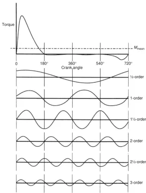
During the 180 crankshaft movement on the power stroke from TDC to BDC, the effective radius of the crank-arm will increase from zero at the top of its stroke to a maximum in the region of mid-stroke and then decrease to zero again at the end of its downward movement (Fig. 1.1-10). This implies that the torque on the power stroke is continually varying. Also, there will be no useful torque during the idling strokes. In fact some of the torque on the power stroke will be cancelled out in overcoming compression resistance and pumping losses, and the torque quoted by engine manufacturers is always the average value throughout the engine cycle.
The average torque developed will vary over the engine’s speed range. It reaches a maximum at about mid-speed and decreases on either side (Fig. 1.1-11).
1.1.6.4 Engine power
Power is the rate of doing work. When applied to engines, power ratings may be calculated either on the basis of indicated power (i.p.), that is the power actually de-veloped in the cylinder, or on the basis of brake power (b.p.), which is the output power measured at the crankshaft. The b.p. is always less than the i.p., due to frictional and pumping losses in the cylinders and the reciprocating mechanism of the engine.
Since the rate of doing work increases with piston speed, the engine’s power will tend to rise with crank-shaft speed of rotation, and only after about two-thirds of the engine’s speed range will the rate of power rise drop off (Fig. 1.1-11).
The slowing down and even decline in power at the upper speed range is mainly due to the very short time available for exhausting and for inducing fresh charge into the cylinders at very high speeds, with a resulting re-duction in the cylinders’ mean effective pressures.
Different countries have adopted their own standardised test procedures for measuring engine per-formance, so slight differences in quoted output figures
will exist. Quoted performance figures should therefore always state the standard used. The three most important standards are those of the American Society of Automo-tive Engineers (SAE), the German Deutsch Industrie Normale (DIN), and the Italian Commissione technica di Unificazione nell Automobile (CUNA).
The two methods of calculating power can be expressed as follows:
i:p: ¼ pLANn60 000
where i.p.¼indicated power (kW) p¼effective pressure (kN/m2) L¼length of stroke (m)
A¼cross-sectional area of piston (m2) N¼crankshaft speed (rev/min) and n¼number of cylinders
b:p: ¼ 260 000pTN
where b.p.¼brake power (kW)
p¼3.142
T¼engine torque (N m) and N¼crankshaft speed (rev/min)
The imperial power is quoted in horsepower (hp) and is defined in terms of foot pounds per minute. In imperial units one horsepower is equivalent to 33 000 ft lb per minute or 550 ft lb per second. A metric horsepower is defined in terms of Newton-metres per second and is equal to 0.986 imperial horsepower. In Germany the ab-breviation for horsepower is PS derived from the trans-lation of the words ’Pferd-Sta¨rke’ meaning horse strength. The international unit for power is the watt, W, or more usually the kilowatt, kW, where 1 kW¼1000 W.
Conversion from watt to horsepower and vice versa is:
1 kW¼1.35 hp and 1 hp¼0.746 kW
1.1.6.5 Engine cylinder capacity
Engine sizes are compared on the basis of total cylinder swept volume, which is known as engine cylinder capacity. Thus the engine cylinder capacity is equal to the piston displacement of each cylinder times the number of cylinders,
i:e:VE ¼ Vn 1000
whereVE¼engine cylinder capacity (litre) V¼piston displacement (cm3) and n¼number of cylinders
Piston displacement is derived from the combination of both the cross-sectional area of the piston and its stroke. The relative importance of each of these di-mensions can be demonstrated by considering how they affect performance individually.
The cross-sectional area of the piston crown influences the force acting on the connecting-rod, since the product Fig. 1.1-10 Torque variation during crankshaft rotation (p¼
cylinder gas pressure;F¼connecting-rod thrust;R¼ crank-throw;r¼effective crank radius;T¼turning-effort or torque).
Fig. 1.1-11 Torque and power variation over engine speed range.
16
of the piston area and the mean effective cylinder pres-sure is equal to the total piston thrust;
i:e: F ¼ pA
where F¼piston thrust (kN)
p¼mean effective pressure (kN/m2) and A¼cross-sectional area of piston (m2)
The length of the piston stroke influences both the turning-effort and the angular speed of the crankshaft. This is because the crank-throw length determines the leverage on the crankshaft, and the piston speed divided by twice the stroke is equal to the crankshaft speed;
i:e: N ¼ 2vL
where N¼crankshaft speed (rev/min) v¼piston speed (m/min) and L¼piston stroke (m)
This means that making the stroke twice as long doubles the crankshaft turning-effort and halves the crankshaft angular speed for a given linear piston speed. The above shows that the engine performance is de-cided by the ratio of bore to stroke chosen for a given cylinder capacity.
1.1.7 Compression-ratio
In an engine cylinder, the gas molecules are moving about at considerable speed in the space occupied by the gas, colliding with other molecules and the boundary surfaces of the cylinder head, the cylinder walls, and the piston crown. The rapid succession of impacts of many millions of molecules on the boundary walls produces a steady continuous force per unit surface which is known as pressure (Fig. 1.1-12).
When the gas is compressed into a much smaller space, the molecules are brought closer to one another. This raises the temperature and greatly increases the speed of the molecules and hence their kinetic energy, so more violent impulses will impinge on the piston crown. This increased activity of the molecules is experienced as increased opposition to movement of the piston towards the cylinder head.
The process of compressing a constant mass of gas into a much smaller space enables many more molecules to impinge per unit area on to the piston. When burning of the gas occurs, the chemical energy of combustion is rapidly transformed into heat energy which considerably increases the kinetic energy of the closely packed gas molecules. Therefore the extremely large number of molecules squeezed together will thus bombard the piston crown at much higher speeds. This then means
that a very large number of repeated blows of consider-able magnitude will strike the piston and so push it to-wards ODC.
This description of compression, burning, and expan-sion of the gas charge shows the importance of utilising a high degree of compression before burning takes place, to improve the efficiency of combustion. The amount of compression employed in the cylinder is measured by the reduction in volume when the piston moves from BDC to TDC, the actual proportional change in volume being expressed as the compression-ratio.
The compression-ratio may be defined as the ratio of the maximum cylinder volume when the piston is at its outermost position (BDC) to the minimum cylinder volume (the clearance volume) with the piston at its innermost position (TDC) – that is, the sum of the swept and clearance volumes divided by the clearance volume,
i:e: CR ¼ VsþVc Vc
where CR¼compression ratio Vs¼swept volume (cm3) Vc¼clearance volume (cm3)
Petrol engines have compression-ratios of the order of 7:1 to 10:1; but, to produce self-ignition of the charge, diesel engines usually double these figures and may have values of between 14:1 and 24:1 for naturally aspirated (depression-induced filling) types, depending on the design.
Fig. 1.1-12 Illustration of compression-ratio.
Section
Two
Engine testing
Section
Two
Section
Two
Section
Two
Section
Two
Section
Two
2.1
Chapter
2.1
Measurement of torque, power,
speed and fuel consumption;
acceptance and type tests,
accuracy of the measurements
A.J. Martyr and M.A. Plint
2.1.1 Introduction
The torque produced by a prime mover under test is resisted and measured by the dynamometer to which it is connected. The accuracy with which a dynamometer measures both torque and speed is fundamental to all the other derived measurements made in the test cell.
In this chapter the principles of torque measurement are reviewed and then the types of dynamometer are reviewed in order to assist the purchaser in the selection of the most appropriate machine.
2.1.2 Measurement of torque:
trunnion-mounted (cradle)
machines
The essential feature of trunnion-mounted or cradled dynamometers is that the power absorbing element of the machine is mounted on bearings coaxial with the machine shaft and the torque is restrained and measured by some kind of transducer acting tangentially at a known radius from the machine axis.
Until the beginning of the present century, the great majority of new and existing dynamometers used this method of torque measurement. In traditional machines the torque measurement was achieved by physically balancing a combination of dead weights and a spring balance against the torque absorbed (Fig. 2.1-1). As the stiffness of the balance was limited, it was necessary to adjust its position depending on the torque, to ensure that the force measured was accurately tangential.
Modern trunnion-mounted machines, shown di-agrammatically in Fig. 2.1-2, use a force transducer,
almost invariably of the strain gauge type, together with an appropriate bridge circuit and amplifier. The strain gauge transducer or ‘load cell’ has the advantage of being extremely stiff, so that no positional adjustment is nec-essary, but the disadvantage of a finite fatigue life after a (very large) number of load applications. The backlash and ‘stiction’-free mounting of the transducer between carcase and base is absolutely critical.
The trunnion bearings are either a combination of a ball bearing (for axial location) and a roller bearing or hydrostatic type. These bearings operate under
T
R
F
W
Fig. 2.1-1 Diagram of Froude type, trunnion-mounted, sluice-gate dynamometer measuring torque with dead weights and spring balance.
Engine Testing, 3rd edn; ISBN: 9780750684392
unfavourable conditions, with no perceptible angular movement, and the rolling element type is consequently prone to brinelling, or local indentation of the races, and to fretting. This is aggravated by vibration that may be transmitted from the engine and periodical inspection and turning of the outer bearing race is recommended in order to avoid poor calibration. A Schenck dynamometer design (Fig. 2.1-3) replaces the trunnion bearings by two radial flexures, thus eliminating possible friction and wear, but at the expense of the introduction of torsional stiffness, of reduced capacity to withstand axial loads and of possible ambiguity regarding the true centre of rotation, particularly under side loading.
2.1.3 Measurement of torque using
in-line shafts or torque flanges
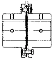
A torque shaft dynamometer is mounted in the drive shaft between engine and brake device. It consists essentially of a flanged torque shaft fitted with strain gauges and designs are available both with slip rings and with RF signal transmission. Fig. 2.1-4 is a brushless torque shaft unit intended for rigid mounting.
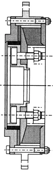
More common in automotive testing is the ‘disc’ type torque transducer, commonly known as a torque flange (Fig. 2.1-5), which is a device that is bolted directly to the input flange of the brake and transmits data to a static antenna encircling it.
A perceived advantage of the in-line torque mea-surement arrangement is that it avoids the necessity, discussed below, of applying torque corrections under transient conditions of torque measurement. However, not only are such corrections, using known constants,
trivial with modern computer control systems, but there are also important problems that may reduce the inherent accuracy of this arrangement.
For steady state testing, a well-designed and main-tained trunnion machine will give more consistently auditable and accurate torque measurements than the inline systems; the justification for this statement can be listed as follows:
The in-line torque sensor has to be oversized for the rating of its dynamometer and being oversized the resolution of the signal is lower. The transducer has to be overrated because it has to be capable of dealing with the instantaneous torque peaks of the engine which are not experienced by the load cell of a trunnion-bearing machine.
The transducer forms part of the drive line and requires very careful installation to avoid the imposition of bending or axial stresses on the torsion sensing element from other components or its own clamping device.
The in-line device is difficult to protect from temperature fluctuations within and around the drive line.
Calibration checking of these devices is not as easy as for a trunnion-mounted machine; it re-quires a means of locking the dynamometer shaft in addition to the fixing of a calibration arm in a horizontal position without imposing bending stresses.
Unlike the cradled machine and load cell, it is not possible to verify the measured torque of an in-line device during operation.
It should be noted that, in the case of modern alternating current (a.c.) dynamometer systems, the tasks of torque measurement and torque control may use different data acquisition paths. In some installations the control of the trunnion-mounted machine may use its own torque cal-culation and control system, while the test values are taken from an inline transducer such as a torque shaft.
2.1.4 Calibration and the
assessment of errors in torque
measurement
We have seen that in a conventional dynamometer, torqueTis measured as a product of torque arm radius Rand transducer forceF.
Calibration is invariably performed by means of acalibration arm,supplied by the manufacturer, which is bolted to the dynamometer carcase and carries dead weights which apply a load at a certified radius. The manufacturer certifies the distance between the axis of the weight hanger bearing and an axis defined by a line
R
Fig. 2.1-2 Diagram of trunnion-mounted dynamometer measuring torque with a load cell.
22
10
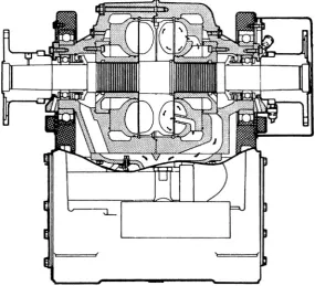
9 4 8 1 5 7 2 3
11 12 6 13 14
Fig. 2.1-3 Schenck, dry gap, disc type eddy-current dynamometer 1, rotor; 2, rotor shaft; 3, coupling flange; 4, water outlet with thermostat; 5, excitation coil; 6, dynamometer housing; 7, cooling chamber; 8, air gap; 9, speed pick-up; 10, flexure support; 11, base; 12, water inlet; 13, joint; 14, water outlet pipe.
A = Mounting flange
A 3 4 5 6 7 B
1 1 = Torsion element (rotor) 2 = Applied SGs
3 = Spindle bearing 4 = Housing (stator) 5 = Elastic seal
6 = Capacitive transmission 7 = Inductive transmission 8 = Toothed ring for speed measurement 9 = Speed pick-up 10 = Cable connection box 2
8
9 10
B = Flange for torque introduction
Fig. 2.1-4 Brushless torque-shaft for mounting in shaft-line between engine and ‘brake’.
joining the centres of the trunnion bearings (not the axis of the dynamometer, which indeed need not precisely coincide with the axis of the trunnions).
There is no way, apart from building an elaborate fix-ture, in which the dynamometer user can check the accuracy of this dimension: he is entirely in the hands of the manufacturer. The arm should be stamped with its effective length. For R&D machines of high accuracy the arm should be stamped for the specific machine.
The ‘dead weights’ should in fact be more correctly termed ‘standard masses’. They should be certified by an appropriate standards authority located as near as possi-ble to the geographical location in which they are used. The force they exert on the calibration arm is the product of their mass and the local value of ‘g’. This is usually assumed to be 9.81 m/s2and constant: in fact this value is only correct at sea level and a latitude of about 47N. It increases towards the poles and falls towards the equator, with local variations. As an example, a machine calibrated in London, whereg¼9.81 m/s2, will read 0.13 per cent high if recalibrated in Sydney, Australia and 0.09 per cent low if recalibrated in St Petersburg without correcting for the different local values ofg.
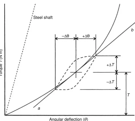
These are not negligible variations if one is hoping for accuracies better than 1 per cent. The actual process of calibrating a dynamometer with dead weights, if treated rigorously, is not entirely straightforward. We are confronted with the facts that no transducer is perfectly linear in its response, and no linkage is perfectly fric-tionless. We are then faced with the problem of adjusting the system so as to ensure that the (inevitable) errors are at a minimum throughout the range.
A suitable calibration procedure for a machine using a typical strain-gauge load cell for torque measurement is as follows.
The dynamometer should not be coupled to the engine. After the system has been energized long enough to warm up the load cell output is zeroed with the
machine in its normal no-load running condition (cooling water on, etc.) and the calibration arm weight balanced by equal and opposite force. Dead weights are then added to produce approximately the rated maximum torque of the machine. This torque is calculated and the digital indicator set to this value.
The weights are removed, the zero reading noted, and weights are added, preferably in 10 equal increments, the cell readings being noted. The weights are removed in reverse order and the readings again noted.
The procedure described above means that the load cell indicator was set to read zero before any load was applied (it did not necessarily read zero after the weights had been added and removed), while it was adjusted to read the correct maximum torque when the appropriate weights had been added.
We now ask: is this setting of the load cell indicator the one that will minimize errors throughout the range and are the results within the limits of accuracy claimed by the manufacturer?
Let us assume we apply this procedure to a machine having a nominal rating of 600 N m torque and that we have six equal weights, each calculated to impose a torque of 100 N m on the calibration arm.Table 2.1-1 shows the indicated torque readings for both increasing and decreasing loads, together with the calculated torques applied by the weights. The corresponding errors, or the differences between torque applied by the calibration weights and the indicated torque readings are plotted in Figs. 2.1-6 and 2.1-7.
The machine is claimed to be accurate to within
0.25 per cent of nominal rating and these limits are shown. It will be clear that the machine meets the claimed limits of accuracy and may be regarded as sat-isfactorily calibrated.
Antenna segments
Rotor
Adaptor flange Measuring body
Fig. 2.1-5 Shaft-line components of a torque flange.
Table 2.1-1 Dynamometer calibration (example taken from actual machine)
It is usually assumed, though it is not necessarily the case, that hysteresis effects, manifested as differences between observed torque with rising load and with falling load, are eliminated when the machine is running, due to vibration, and it is a common practice when calibrating to knock the machine carcase lightly with a soft mallet after each load change to achieve the same result.
It is certainly not wise to assume that the ball joints invariably used in the calibration arm and torque trans-ducer links are frictionless. These bearings are designed for working pressures on the projected area of the con-tact in the range 15 to 20 MN/m2and a ‘stick slip’ co-efficient of friction at the ball surface of, at a minimum, 0.1 is to be expected. This clearly affects the effective arm length (in either direction) and must be relaxed by vibration.
Some large dynamometers are fitted with torque multiplication levers, reducing the size of the calibration masses. In increasingly litigious times and ever more stringent health and safety legislation, the frequent han-dling of multiple 20 or 25 kg weights may not be advisable. It is possible to carry out torque calibration by way of ‘master’ load cells or proving rings.*These devices have to be mounted in a jig attached to the dynamometer and give an auditable measurement of the force being applied on the target load cell by means of a hydraulic actuator. Such systems produce a more complex ‘audit trail’ in order to refer the calibration back to national standards.
It is important when calibrating an eddy-current ma-chine that the water pressure in the casing should be at operational level, since pressure in the transfer pipes can give rise to a parasitic torque. Similarly, any disturbance to the run of electrical cables to the machine must be avoided once calibration is completed. Finally, it is possible, par-ticularly with electrical dynamometers with forced
cooling, to develop small parasitic torques due to air discharged non-radially from the casing. It is an easy matter to check this by running the machine uncoupled under its own power and noting any change in indicated torque.
Experience shows that a high grade dynamometer such as would be used for research work, after careful calibration, may be expected to give a torque indication that does not differ from the absolute value by more than about0.1 per cent of the full load torque rating of the machine.
Systematic errors such as inaccuracy of torque arm length or wrong assumptions regarding the value ofgwill certainly diminish as the torque is reduced, but other errors will be little affected: it is safer to assume a band of uncertainty of constant width. This implies, for example, that a machine rated at 400 Nm torque with an accuracy of0.25 per cent will have an error band of1 N. At 10 per cent of rated torque, this implies that the true value may lie between 39 and 41 Nm. It is as well to match the size of the dynamometer as closely as possible with the rating of the engine.
All load cells used by reputable dynamometer man-ufacturers will compensate for changes in temperature, though their rate of response to a change may vary. They will not, however, be able to compensate for internal temperature gradients induced, for example, by air blasts from ventilation fans or radiant heat from exhaust pipes.
The subject of calibration and accuracy of dyna-mometer torque measurement has been dealt with in some detail, but this is probably the most critical mea-surement that the test engineer is called upon to make, and one for which a high standard of accuracy is expected but not easily achieved. Calibration and certification of the dynamometer and its associated system should be 1.000
0.000 100.000 200.000 300.000 400.000 500.000 600.000 700.000
% Error
Fig. 2.1-6 Dynamometer calibration error as percentage of applied torque.
% Error 0.000 100.000 200.000 300.000 400.000 500.000 600.000 700.000
Fig. 2.1-7 Dynamometer calibration error as percentage of full scale.
* A proving ring is a hollow steel alloy ring whose distortion under a rated range of compressive loads is known and measured by means of an internal gauge.