A Microfabricated Planar Digital Microrobot for
Precise Positioning Based on Bistable Modules
Vincent Chalvet, Yassine Haddab
, Member, IEEE
, and Philippe Lutz
, Member, IEEE
Abstract—Size reduction is a constant objective in new
technolo-gies for which very accurate devices are needed when manipulating submillimetric objects. A new kind of microfabricated microrobot based on the use of bistable modules is designed to perform open-loop controlled micropositioning tasks. The DiMiBot (a specific digital microrobot) opens a new paradigm in the design of micro-robots by using mechanical stability instead of complex control strategies. We propose a new architecture of digital microrobot for which forward and inverse kinematics models are easy to use. These kinematic models are validated with finite-element-analysis simu-lations before the fabrication of a real DiMiBot prototype. Tests and characterization of the prototype are made and compared with the desired behavior. Thanks to its submicrometric resolution and to its small dimensions (∼400-µm thickness), it is able to manipulate microobjects in confined environments, where no other robot can be used.
Index Terms—Bistable module, discrete workspace, flexible arms, mechanism design, micro/nano robots.
I. INTRODUCTION
I
N order to meet the needs of microcomponent manipula-tion and assembly, significant research activities have been performed in the field of microrobotics that deals with the de-sign, fabrication, and control of microrobots. These microrobots are intended to perform various tasks in the Microworld (i.e., the world of submillimetric objects), in particular, microma-nipulation tasks of single objects (mechanical or biological) as positioning, characterizing, or sorting, as well as industrial microassembly. Achieving efficient robotic tasks at this scale re-mains a great challenge and requires submicrometric resolution and accuracy in order to interact with micrometric objects. Meth-ods and strategies used to build conventional robots are often not applicable in the microworld. New mechatronic approaches, new actuators, and robot kinematics are needed. Research has shown that the use of active materials to actuate microrobots per-forms better than the use of more traditional actuators. Piezo-electric materials, shape memory alloys, and active polymersManuscript received July 31, 2012; revised November 20, 2012; accepted January 11, 2013. Date of publication February 5, 2013; date of current version June 3, 2013. This paper was recommended for publication by Associate Editor Y. Sun and Editor B. J. Nelson upon evaluation of the reviewers’ comments. This work was supported by the Direction G´en´erale de l’Armement and in part by the french RENATECH network and its FEMTO-ST technological facility.
The authors are with the Automatic Control and Micro-Mechatronic Systems Department (AS2M), FEMTOST Institute, UMR CNRS 6174 -UFC/ENSMM/UTBM, 25000 Besanc¸on, France (e-mail: vincent.chalvet@ femto-st.fr; [email protected]; [email protected]).
Color versions of one or more of the figures in this paper are available online at http://ieeexplore.ieee.org.
Digital Object Identifier 10.1109/TRO.2013.2240174
Fig. 1. (Top) One bistable module: CAD model. (Bottom) Scanning electron microscope image.
have been successfully used to actuate various types of micro-robots. However, despite their intrinsic high resolution, these active materials present some disadvantages, making the design of efficient controllers a hard task [1]. Their behavior is often complex, nonlinear, and sometimes nonstationary. Closed-loop control of the microrobots requires the design and the integration of very small sensors and the use of bulky and expensive instru-ments for signal processing and real-time operating. Packaging and integration of the sensors and actuators is also a hard prob-lem. This is why building multidegree-of-freedom microrobots able to perform complex tasks is difficult. Moreover, in many cases, the size of the robot itself should be very small in order to manipulate microobjects in confined environments. The design of a microrobot contains two parts: the design of end-effector to interact with the manipulated microobjects and the design of microrobot arm used to move the end-effector in the working area. While many research activities have been performed to develop end-effectors compatible with the microworld [2], [3], few have been concerned with the development of microrobot arms adapted to the microworld. Most of current robots are bulky and based on the miniaturization of traditional kinemat-ics, such as anthropomorphic robots (Kleindiek’s MM3A [4]) or delta robots (Asyril’s Pocket Delta [5]). Their size is not really compatible with the microworld and limits considerably the use of microrobots to execute complex tasks in confined environments. Other planar stages better suited for micropo-sitioning tasks use active materials as actuators [6], [7] but are also hardly used in confined environments because of the need of sensors.
In [8] and [9], we have proposed a new paradigm in build-ing microrobots, called digital microrobots. These studies were
dedicated to the design of the bistable modules (see Fig. 1). In this paper, we propose an original design of digital microrobot based on the use of the bistable modules designed in [8] and [9], combined with a flexible structure, that is able to generate a 2-D workspace. The bistable module is composed of three elements: a mechanical bistable structure, two pairs of electrothermal ac-tuators, and two stop blocks. The electrothermal actuators push forth and back the bistable structure, where one pair of actuators push in one direction, to reach each stable position. The stop blocks limit the displacement of the bistable structure between the two positions, as well as give the robustness of each position by adding a blocking force. In this paper, the two robust posi-tions are separated by 30µm and the blocking force is 1.54 mN. As it is mechanically stable, the module does not need a power supply to stay in a given position. Power is only needed when switching between states.
In this paper, we propose an original digital microrobot de-sign. We first introduce the specifications used for this micro-robot before presenting the chosen design and the calculation of its kinematics models. Section IV presents the dimension-ing study of this robot before dealdimension-ing with the microfabrication process and the characterization of a digital microrobot.
II. DIMIBOT
A. Specifications for a Digital Microrobot
Open-loop controllable manipulators were already studied in the macroscale robotics domain with the Variable Geometry Truss (VGT) manipulator in [10], which is a lightweight hyper-redundant 2-D manipulator based on the use of binary actuators. Because of the high redundancy of this robot, complex forward and inverse kinematics models were developed in [11] and [12]. Another 3-D digital manipulator was also developed in [13]: the Binary Robotic Articulated Intelligent Device (BRAID) for space usage purposes. The kinematic architectures used for these robots are not applicable to the design of robots operating at mi-croscale. Assembled architectures are indeed not well adapted to microrobotics because of many drawbacks that are really trou-blesome for precise micromanipulation tasks (friction, backlash, etc.).
Specifications for the design of the microrobot are mainly dictated by common microworld requirements. However, these specifications must be consistent with microfabrication technol-ogy limitations. In order to work in confined environments, the microrobot should be compact. Moreover, to avoid assembly and backlash, a monolithic structure is preferred. Positioning reso-lution should be submicrometric, and forces generated should reach several millinewtons to allow manipulation of various kinds of microobjects in different environments. The workspace wanted is a square with homogeneous distribution of reachable locations without redundancy in order to simplify the model-ing and maximize the reachable space. For mechanical stability and reliability, parallel structures, where all bistable modules are fixed to a unique base, are privileged. According to all these requirements, the design is presented in the following section.
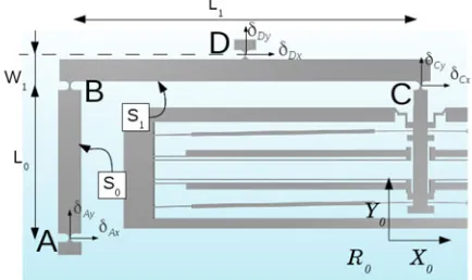
Fig. 2. Robot design: (Left) Kinematic scheme and (right) CAD model.
Fig. 3. Elementary structure from the left side of the structure, which is composed of one bistable module and two beams.
B. Microrobot Design
This microrobot is made in a monolithic microfabricated structure on silicon-on-insulator (SOI) wafer, allowing dimen-sions compatible with confined environments (thickness of
∼400µm). It could, for instance, be useful for applications inside a transmission electron microscope (TEM) for which the sample area is very thin. The design chosen for this microrobot is presented in Fig. 2. With respect to the specifications, a flex-ible structure adapted to microfabrication process is developed to link the displacement of the bistable modules.
The particular kinematics used for the DiMiBot can be di-vided into elementary structures, like the one shown in Fig. 3. This elementary structure is composed of one bistable module connected by a flexible joint (point C) to a first pseudorigid beamS1(oriented in theX0-direction), which is also connected
(at point B) to a second beamS0(oriented in theY0-direction).
The displacement of the middle point of theS1beam (point D)
is generated by the displacement of the bistable module and by the displacement occurring at point A. By associating several of these elementary structures together, the displacement oc-curring in the point A of one elementary structure is generated by the other parts of the structure. The displacement of each module is then cumulatively transmitted to the end-effector of the microrobot.
III. DIMIBOT’SKINEMATICS
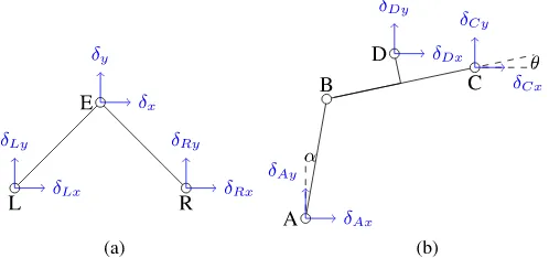
Fig. 4. Kinematic schematics of (a) the end-effector and (b) the elementary structure constituting the digital microrobot.
manipulators, and make use of workspace densities [11], [12] which is not applicable here. In the case of the DiMiBot which is nonredundant, the modeling of the forward and inverse kine-matics is easier.
A. Forward Kinematics
The forward kinematics equation represents the displacement of the end-effector of the robot ([δx δy]T; see Fig. 2) as a
function of the states (0 or 1) of all the bistable modules used. To establish the model, we made several assumptions.
1) The beams are rigid (no deformation). 2) The rotation occurs at the center of the hinges.
3) Rotations are considered to be small so that trigonomet-ric functions are linearized [θ small and α small; see Fig. 4(b)].
These assumptions are consistent with the structure because the displacements occurring are very small.
For the calculation of this forward kinematic equation, we will proceed in several steps. The first step consists of representing the displacement of the end-effector E as a function of the displacements of the two pointsLandRat the bottom of the two end-effector beams [see Fig. 4(a)]. The displacement of these two points are noted [δL x δL y]T for the point L and
[δR x δR y]T for the pointR. The relationship between these
three points is defined by
The next steps represent the values of the displacements
[δL x δL y]T and[δR x δR y]T of pointsLandR as a
func-tion of the states (0 or 1) of every bistable module. The dis-placement of point L is expressed as a function of the bli
∈ {0; 1}(0≤i≤N1−1, numbered from bottom to top, where N1 is the number of modules on the left side of the structure).
The displacement of pointR is expressed as a function ofbrj
∈ {0; 1}(0≤j≤N2−1, numbered from bottom to top, where N2is the number of modules on the right side of the structure).
We consider the elementary structure shown in Fig. 3 for the calculation of these displacements. Each elementary structure
transmits the displacement of one bistable module to the next elementary structure, except for the ones at the top which make a direct link with the base (see Fig. 2), rigidifying the whole structure. The displacement of all the bistable modules is cumu-latively transmitted up to the end-effector. Equation (2), shown below, represents the displacement of point D ([δD x δD y]T)
as a function of the displacement of point C ([δC x δC y]T)
and of the angleθ[see Fig. 4(b)]. The displacement of pointD
is also expressed as a function of the displacement of point A ([δA x δA y]T) and of the anglesθandαin (3), shown below:
With the assumptions mentioned before (small-angle approx-imation), (2) and (3) can be combined into a single equation (4), shown below, representing the displacement of point D as a function of the displacements of pointsAandC, where the dis-placement of pointCis actually the displacement of the module (δC x = 0andδC y = ∆×bli):
To identify the elementary structure of the left side of the microrobot (see Fig. 2), we use the same numbering as the corresponding bistable module. We have Ai, Bi,Ci, and Di
connected to the modulebli(0≤i≤2) andA3,B3,C3, and D3for the top elementary structure (for whichC3is fixed, as is A0). In that structure,D3 =L,A3=D2,A2 =D1, andA1 = D0. Using (4), the displacement of pointL([δL x δL y]T) is
calculated as in the following:
=
The displacement of the pointLis then iteratively calculated down to the bottom of the structure, leading to (6) for a robot withN1 modules on the left side of the structure (N1 = 3in
A similar calculation leads to (7) for the right side of the structure and the displacement of pointR:
The displacement of the end-effector can, finally, be expressed as a function of the state of every bistable modulebli andbrj
(0≤i≤N1−1and0≤j ≤N2−1) by combining (1), (6),
and (7). The displacement of the end-effector is expressed in (8) when all the bistable modules of the robot generate the same displacement∆between their two states:
The resolution is deduced from (8) (giving the displacement in
R0referential). It is the distance between two neighbor positions
in theX1- andY1-directions (see Fig. 5). A modulebligenerates
a displacement on the X1-direction (bri in the Y1-direction).
The resolution can be decoupled on each of these directions. The resolution isrx =
The size of the workspace in the X1-direction can be
ex-pressed as2N1 ×r
x=
√
2∆2(12 +W1
L1), which is independent
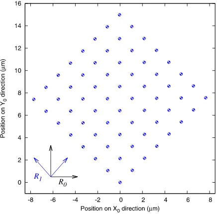
Fig. 5. Workspace generated with a microrobot containing six bistable mod-ules for which the displacement between the two states is∆ =30µm.
of the number of modules used (independent of N1). In the Y1-direction, it is2N2 ×ry, resulting in the same expression.
B. Workspace Generation
These particular kinematics generate a 2-D discrete workspace, meeting the specifications established for the de-sign of the flexible structure. In the case of a robot with six bistable modules (N1 =N2= 3), like in the kinematic scheme
of Fig. 2, the workspace is composed of 64 distinct discrete positions that are regularly spread in a Cartesian workspace. All these positions are addressed by a 6-bit binary word composed of the state of each bistable module. By considering a displace-ment of∆ =30µm for each bistable module (within a structure with dimensionsW1=380µm,L1 =5.8 mm), this workspace
(see Fig. 5) is arranged inside a square of 12µm length with a resolution of 1.5µm.
The resolution of the workspace can be improved by increas-ing the number of bistable modules, leadincreas-ing to submicrometric resolution with high repeatability. For instance, by adding two more bistable modules at the bottom of the structure (one on each side of the structure), the number of reachable points be-comes 256 (28), and the resolution becomes two times better
(750 nm), while the size of the workspace is unchanged (square of 12-µm length). Each time one module is added on one side of the structure, the resolution is divided by 2 in one direction of the workspace (X1-direction if it is added on theX0
negative-half-plane side andY1-direction if it is on theX0positive-half-plane
side; see Fig. 5).
In order to increase the size of the workspace, two approaches are possible.
2) Move the pointLalong the−X0-axis and pointRalong
the+X0-axis, while maintaining an angle of π2 between
the two end-effector beams (in order to preserve the square shape of the workspace).
C. Inverse Kinematics
The inverse kinematics model determines the joint param-eters that provide a desired position of the end-effector. This modeling is quite complex for digital robots due to the nec-essary knowledge of all reachable points. The points list can be difficult to handle for calculation when considering robots containing a huge number of binary actuators (possibly over 20). The studies shown in [15]–[17] use the high redundancy of digital robots to allow approximations in the calculation of the inverse kinematics model.
For the digital microrobot, the inverse kinematics model rep-resents the Boolean values of allbliandbrjfor a desired position
in the workspace. The inverse kinematics model is established by understanding the pattern of the point distribution inside this workspace. As demonstrated by the forward kinematics model, the modules on the left side of the structure generate a displace-ment on theX1-direction, and the modules on the right side of
the structure generate a displacement in theY1-direction. The
inverse kinematics model can then be decoupled by considering separately each side of the structure. The points on each direc-tion are, furthermore, linearly organized on each direcdirec-tion (with a resolution determined by the forward kinematics model), start-ing from point0to point2N1 −1or to point2N2 −1forX
1
-andY1-directions, respectively.
Equation (9) defines the state of every bistable module i
(0≤i≤N1−1) of the left side of the structure and module j (0≤j≤N2 −1) of the right side for any desired position [xd yd]T (inR1referential) inside the square workspace:
bl
i =¬((round(xdrx) &2i) == 0)
brj =¬((round(ydry) &2j) == 0)
(9)
where
1) xd is the component along the X1-axis of the desired
position;
2) yd is the component along theY1-axis of the desired
po-sition;
3) bli is the Boolean representing the state of the modulei
on theX0 negative half plane of the structure (numbered
on theY0positive direction);
4) brj is the Boolean representing the state of the modulej
on theX0 positive half plane of the structure (numbered
on theY0positive direction);
5) rxis the resolution of the workspace in theX1-direction;
6) ry is the resolution of the workspace in theY1-direction;
7) ¬is the Boolean functionNOT; 8) &is the bitwiseANDfunction.
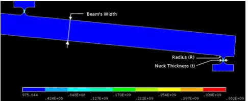
Fig. 6. Elements of the structure studied with the results of the FEA software ANSYS.
IV. DIMENSIONING OF THEFLEXIBLESTRUCTURE
A. Joint Dimensioning
This digital microrobot is entirely microfabricated and built in a monolithic structure. The use of flexure hinges is used for creating micro/nanopositioning systems with high resolu-tion [18], [19]. Unlike tradiresolu-tional revolute joints, flexure hinges prevent backlash and friction, which are the main cause of inaccuracy in positioning and are very troublesome for ma-nipulation tasks at microscale. The flexure hinges, as well as some other parameters of the robotic structure, will be char-acterized in order to provide good behavior of the robot. The results of finite-element analysis (FEA) will be used for that purpose.
As the bistable modules were already dimensioned in our previous works [8], [9], the simulation will only deal with the robotic structure. It is composed of a series of two elements: the pseudorigid beams and the flexure hinges (see Fig. 6). The dimensions choice will depend on two simulation results:
1) the mechanical stress generated inside the structure by its deformations;
2) the force applied by the structure onto the bistable modules.
While undergoing the displacement of the bistable modules, the robotic structure will deform and tend to return to its rest position (position in which it was after fabrication). A restoring force is then applied by the structure onto each bistable module. In order to produce a stable and robust displacement of the end-effector of the microrobot and allow its usage in open-loop control (which is the main purpose for designing such digital robots), the force applied on every module should not exceed a given threshold which is the blocking force of the stop blocks (1.54 mN). The stress reached inside the structure should also not exceed a given threshold which is the silicon’s rupture stress (assumed to be 1 GPa in this study).
Fig. 7. FEA simulation results: force and stress in the structure depending on the hinge’s dimensions (neck thickness and radius).
All the flexure hinges of the flexible structures (represented as circles on the kinematic scheme of Fig. 2) have the same dimensions. In order to find the optimal dimension for these flexure hinges with respect to the constraints mentioned before (stress and force constraints), FEA simulation was made for several dimensions of these flexure hinges.
Fig. 7 represents the value of the maximal force applied on all the bistable modules (left figure) and the maximal stress inside the structure (right figure) for every reachable point of the workspace and for different dimensions of the hinges (see Fig. 6), i.e., for hinges’ radius from 20 to 100µm (on the ab-scissa), and neck thickness from 10 to 20µm (the three different curves).
Because of the size uncertainties in the microfabrication pro-cesses (about 2µm due to overetching), the different elements of the structure should not be too small. If we choose a neck thickness of 15µm, and a radius of 60µm for all the flexure hinges of the structure, we ensure the good behavior of this structure.
B. Robustness Analysis
In robotics, robustness analysis deals with the ability of the robot’s end-effector to maintain its position when exposed to external perturbations. It is an important property for manipula-tion tasks, which ensures the good behavior of the manipulator. Robustness is traditionally acquired with control feedback, but in the case of the DiMiBot which is used without a sensor, we can only consider the mechanical robustness of the robotic structure. When using flexible elements in the structure, exter-nal perturbation induces small deformations of the beams, and thus, errors in the reached position induce a lack of robustness. The study of the previous section ensured the good behavior of the digital microrobot in standard usage, i.e., with an unladen end-effector, and without an element (objects or obstacles) in the working area. The robustness study of the structure will now consider a perturbation force applied on the end-effector of the structure. In order to be used as a manipulating microrobot used for positioning tasks, it should be robust facing forces of several millinewtons.
The forces applied on every module and the stress inside the structure were simulated for all the positions reachable by the
TABLE I
COMPARISONBETWEENFEA SIMULATIONRESULTS ANDMODEL’S
CALCULATION
robot while it undergoes an external force from 0 to 10 mN. The main consequence of this force is a small displacement of the whole workspace. This study is mainly focused on a robot with beam’s width of 300µm and hinges of 15-µm thickness and 60-µm radius. For this particular design, a force of 5 mN ap-plied on the end-effector induces a workspace displacement of 0.5µm. However, this displacement can be reduced by increas-ing the beamwidth. For instance, this displacement becomes al-most ten times smaller with a beamwidth of 700µm. This small displacement provides compliance to the robot’s end-effector, which can be useful for several tasks.
The most constraining characteristic is the force applied on every bistable module. This force should never exceed the limit of 1.54 mN. For a structure with beams of 300-µm width, the structure can undergo an external force of 3 mN before reaching the blocking force on one of the six bistable modules, while with beams of 700µm, the external force cannot exceed 1.8 mN. This means that when applying a strong force (in this case over 3 mN) on the end-effector of the robot, one of the six bistable modules could switch back on its own, and the position of the end-effector would be lost. As the first prototype of the digital microrobot will undergo testing of the force it can bear, we chose to use the structure that can handle the strongest external force, i.e., with a beamwidth of 300µm.
C. Finite-Element-Analysis Simulation Versus Kinematic Model
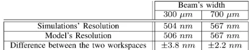
The simulations made with the FEA software can also be used for a first validation of the geometric models that have been established before. For this, the comparison between the workspace generated by the finite-element simulation and the one calculated by the geometric model is made. The results are shown in Table I which focuses on the differences between a structure containing beams of 300-µm width and a structure with 700-µm-width beams. The difference between the simula-tion and the model is established for each of the 64 reachable po-sitions. The difference between the two workspaces is±3.8 nm in the first case (300-µm-width beams) and ±2.2 nm for the second (700-µm-width beams), which is negligible compared with the resolution of the workspace (∼1.5µm). This mismatch is due to the deformation of the beams which is not taken into account by the geometric model.
Fig. 8. Flowchart of the microfabrication process.
Finally, we decided to microfabricate a DiMiBot composed of beams of 300-µm width and circular flexure hinges of 15-µm neck thickness and 60-µm radius.
V. MICROFABRICATION
This digital microrobot is a monolithic structure microfabri-cation on a unique SOI wafer. The 4-in wafer is composed of three layers: The bottom one (handle layer) is a silicon layer of 300-µm thickness, the middle one (buried oxide “box” layer) is a silicon oxide (SiO2) layer of 2-µm thickness, and finally,
the top one (device layer) is a silicon layer of 100-µm thick-ness. The mobile parts of the digital microrobot are built on the device layer (100-µm thickness), while the fixed base of the robot is composed of the whole wafer (402-µm thickness). The choice to use an SOI wafer was made in order to use the box layer to electrically isolate the aluminum paths used to power the different bistable modules. It, furthermore, ensures a con-stant thickness of the mobile elements of the robot (built on the 100-µm device layer) during microfabrication. The micro-fabrication process is based on the use of chemical etching of silicon and silicon oxide in a deep reactive ion etching machine. The microfabrication process is given in the flowchart shown in Fig. 8.S1813,SP R220−3.0, andAZ9260 are photoresists used as masks to protect the parts we do not want to remove during the chemical etching process.
During steps (2)–(4), the electrical paths in aluminum are fabricated. In step (2), a 800-nm layer of aluminum is deposited onto the whole wafer by pulverization, and the photoresist is spin coated onto the aluminum layer. After that [step (3)], the photoresist is patterned and the aluminum etched, before doing the ohmic contact [step (4)] by diffusing the aluminum inside the silicon. Steps (5)–(7) are the etching of the handle layer, while in step (8), we remove the box layer, and finally, steps (9)–(11) are the etching of the device layer and the release of the microfabricated structure.
A digital microrobot containing four bistable modules was microfabricated. The dimensions of this robot are 36.5 mm×
Fig. 9. Digital microrobot containing four bistable modules, and zoom on its end-effector while manipulating a 150-µm diameter glass ball.
24.5 mm with a thickness of 402µm. Each bistable module generates a displacement of∆ =30µm.
Fig. 9 shows a picture of this microrobot, with a zoom on the end-effector during the manipulation of a 150-µm diameter glass ball.
VI. CHARACTERIZATION
The characterization was done on the digital microrobot con-taining four bistable modules (N1 =N2 = 2), thus generating
a workspace with 16 reachable positions.
A. Necessary Energy for Switching Modules
As this microrobot does not need any power to maintain its position, an interesting parameter is the necessary energy for switching the modules. The conditions in which this character-ization was made are not optimized, but these results give the first idea concerning the power consumption of this robot.
After microfabrication, the average resistance of one elec-trothermal actuator is 332.32Ω(resistivity of the silicon used is 0.0 2Ω·cm). These actuators are used by pair (in parallel) for switching the bistable module from one state to the other. Each of the two pairs of one bistable module is used for switching in one direction (top or bottom).
The minimum time of input current into the pair of electrother-mal actuators needed for switching the module is measured for each state of every bistable module, and the energy is calcu-lated. These results were made for a 16-V input voltage. The current input inside one pair of electrothermal actuators is less than 100 mA for an actuation time lower than 22 ms. The re-sults showed a maximum input energy of 23.5 mJ for switching a module from one state to the other.
As this energy is only needed when switching a module, this makes it a low powered microrobot.
B. Workspace Generation
This study was made with the Micro System Analyzer
TABLE II
DISPLACEMENTGENERATED ANDREPEATABILITY BYEACH OF THEFOUR
BISTABLEMODULES OF THEDIGITALMICROROBOT
Fig. 10. Scatter plot of all the reached points of the workspace during repeata-bility characterization.
Because of uncertainties during the microfabrication process, mainly due to overetching, the displacement between two states of each bistable module is larger than expected, as we can see in the second column of Table II. The third column of this table is the generated displacement at the end-effector of the microrobot for the actuation of each bistable module. This calculation was made with the forward kinematic model by adjusting the value of the displacement of the bistable modules (∆). Actually, the calculation is slightly different from the kinematic model be-cause the measurement was made on an other point than the center of the end-effector’s joint. These results show a good be-havior of the complete microrobot. Even if there is a little error between the theoretical workspace and the measured one (error
∼5%), these results coincide with the established model. The global generated workspace of this microrobot is rep-resented in Fig. 10. This figure focuses on the repeatability of each position reachable by the microrobot. We can distinguish all 16 reachable points and their repeatability.
C. Repeatability Study
The repeatability of a robot represents its ability to return to a given position. Repeatability studies have been made for all the bistable modules of this robot. The results are reported in the last column of Table II. This experiment shows a repeatability under 100 nm, while the resolution of this robot is∼3.8µm. The
results obtained with this first prototype are very encouraging and show the real contribution of designing such a microrobot.
VII. CONCLUSION
This study opens a new paradigm in the design of micro-robots. By making use of bistable modules, it allows the gen-eration of stable and robust discrete reachable positions. The architecture used generates a Cartesian discrete workspace with a resolution of 1.5µm and allows its usage in the open-loop con-trol. The flexible structure prevents any mechanical drawbacks (backlash, friction, etc.) and can withstand external forces up to 3 mN. The mechanical stability of the bistable modules, fur-thermore, allows energy saving because energy supply is only needed when switching modules, not for maintaining positions. Its small thickness (∼400µm) and its open-loop control (no sensor needed) enable these robots to perform micromanipu-lation tasks in confined environments such as inside a TEM. The experiments done on the first prototype (a microrobot with four bistable modules) allowed the first validation of a real dig-ital microrobot. The generated workspace of this prototype is consistent with the kinematic models established.
Further studies dealing with actuation energy optimization and switching dynamic will be performed. The microfabrica-tion process should also be optimized in order to generate dis-placements closer to the ones expected. Trajectory planning strategies, which are generally complex for discrete workspaces, will be studied. New architectures generating more complex workspaces (even in three dimensions) will be considered.
REFERENCES
[1] M. Rakotondrabe, C. Cl´evy, and P. Lutz, “Hysteresis and vibration com-pensation in a nonlinear unimorph piezocantilever,” inProc. IEEE/RSJ-IROS Int. Conf. Intell. Robot. Syst., Nice, France, Sep. 2008, pp. 558–563. [2] F. Beyeler, A. Neild, S. Oberti, D. J. Bell, Y. Sun, J. Dual, and B. J. Nelson, “Monolithically fabricated microgripper with integrated force sensor for manipulating microobjects and biological cells aligned in an ultrasonic field,”J. Microelectomech. Syst., vol. 16, no. 1, pp. 7–15, 2007. [3] K. Kim, X. Liu, Y. Zhang, and Y. Sun, “Nanonewton force-controlled
manipulation of biological cells using a monolithic MEMS microgripper with two-axis force feedback,”J. Micromech. Microeng., vol. 18, no. 5, 055013 (8pp), 2008.
[4] (2013). [Online]. Available: http://www.nanotechnik.com/mm3a-em.html [5] (2013). [Online]. Available: http://www.asyril.ch/products/delta-robots.
html
[6] J. Dong, D. Mukhopadhyay, and P. M. Ferreira, “Design, fabrication and testing of a silicon-on-insulator (SOI) MEMS parallel kinematics XY stage,”J. Micromech. Microeng., vol. 17, no. 6, p. 1154, 2007.
[7] Y. Tian, B. Shirinzadeh, D. Zhang, X. Liu, and D. Chetwynd, “Design and forward kinematics of the compliant micro-manipulator with lever mechanisms,”J. Precis. Eng., vol. 33, no. 4, pp. 466–475, Oct. 2009. [8] Q. Chen, Y. Haddab, and P. Lutz, “Digital microrobotics based on bistable
modules: Design of compliant bistable structures,” inProc. IEEE/ASME Int. Conf. Mechatron. Embedd. Syst. Appl., Beijing, China, Oct. 2008, pp. 36–41.
[9] Q. Chen, Y. Haddab, and P. Lutz, “Microfabricated bistable module for digital microrobotics,”J. Micro-Nano Mechatron., vol. 6, pp. 1–12, 2010. [10] G. S. Chirikjian, “A binary paradigm for robotic manipulators,” inProc. IEEE Int. Conf. Robot. Autom., San Diego, CA, USA, May 1994, vol. 4,, pp. 3063–3069.
[12] D. Lees and G. S. Chirikjian, “An efficient method for computing the forward kinematics of binary manipulators,” inProc. IEEE Int. Conf. Robot. Autom., Minneapolis, MN, USA, Apr. 1996, vol. 2, pp. 1012–1017. [13] V. A. Sujan, M. D. Lichter, and S. Dubowski, “Lightweight hyper-redundant binary elements for planetary exploration robots,” in Proc. IEEE/ASME Int. Conf. Adv. Intell. Mechatron., Como, Italy, 2001, vol. 2, pp. 1273–1278.
[14] M. D. Lichter, V. A. Sujan, and S. Dubowsky, “Computational issues in the planning and kinematics of binary robots,” inProc. IEEE Int. Conf. Robot. Autom., Washington, DC, USA, 2002, vol. 1, pp. 341–346. [15] I. Ebert-Uphoff and G. S. Chirikjian, “Inverse kinematics of discretely
actuated hyper-redundant manipulators using workspace densities,” in
Proc. IEEE Int. Conf. Robot. Autom., Minneapolis, MN, USA, Apr. 1996, vol. 1, pp. 139–145.
[16] D. Lees and G. S. Chirikjian, “A combinatorial approach to trajectory planning for binary manipulators,” inProc. IEEE Int. Conf. Robot. Autom., Minneapolis, MN, USA, Apr. 1996, vol. 3, pp. 2749–2754.
[17] J. Suthakorn and G. S. Chirikjian, “A new inverse kinematics algorithm for binary manipulators with many actuators,”J. Adv. Robot., vol. 15, pp. 225–244, 2001.
[18] Y. Koseki, T. Tanikawa, N. Koyachi, and T. Arai, “Kinematic analysis of translational 3-DOF micro parallel mechanism using matrix method,” in
Proc. IEEE/RSJ Int. Conf. Intell. Robot. Syst., Takamatsu, Japan, 2000, vol. 1, pp. 786–792.
[19] Y. K. Yong, S. S. Aphale, and S. O. R. Moheimani, “Design, identification and control of a flexure-based XY stage for fast nanoscale positioning,”
IEEE J. Trans. Technol., vol. 8, no. 1, pp. 46–54, Jan. 2009.
[20] L. L. Howell,Compliant Mechanisms. New York, NY, USA: Wiley, pp. 135-218, 2001.
Vincent Chalvetreceived the Engineering degree in mechatronics from the National School of Mechanics and Microtechnology, Besanc¸on, France, in 2008 and the M.S. degree in mechatronics and microsystems from the University of Franche-Comt´e, Besanc¸on, in 2009, where he is currently working toward the Ph.D. degree.
During his studies, he has focused on robotics and microsystems. His current research interests in-clude the development of novel microelectromechan-ical digital microrobots for micromanipulation.
Yassine Haddab(M’11) received the Engineering degree in electrical engineering from the University of Tizi-Ouzou, Tizi-Ouzou, Algeria, the M.S. de-gree from the National School of Mechanics and Mi-crotechnology (ENSMM), Besanc¸on, France, and the Ph.D. degree from the University of Franche-Comt´e, Besanc¸on, in 2000.
His research dealt with the design, modeling, and control of micromanipulation systems. Since 2002, he has been an Associate Professor with the ENSMM, where he teaches control and microrobotics. His re-search interests include the design and control of high-precision microrobots and microsystems. He also contributes to the development of microfactory con-cepts and new microrobots architectures.
Philippe Lutz (M’07) received the Engineer de-gree from the National School of Mechanics and Microtechnology (ENSMM), Besanc¸on, France, in 1990, and the Ph.D. degree in automation and com-puter science from the University of Franche-Comt´e, Besanc¸on, in 1994.
He was an Associate Professor with the INSA, Strasbourg, France, from 1994 to 2002. He joined the University of Franche-Comt´e as a Professor in 2002. He was the Head of the research group Automated Systems for Micromanipulation and Microassembly of the AS2M Department of FEMTO-ST Institute from 2005 to 2011. He is currently the Director of the Ph.D. Graduate School of Engineering Science and Microsystems with more than 400 Ph.D. students. His research activities are focused on the design and the control of MicroMechatronic Systems. He is the author of more than 60 refereed publications.
Prof. Lutz received several awards of the IEEE. He serves as an Associate Editor for the IEEE TRANSACTIONS ONAUTOMATIONSCIENCE ANDENGINEER