Informasi Dokumen
- Penulis:
- David Barnett
- David Groth
- Jim McBee
- Pengajar:
- Dr. James S. Tyler
- Sekolah: Sybex, Inc.
- Mata Pelajaran: Network Wiring
- Topik: Cabling: The Complete Guide to Network Wiring
- Tipe: book
- Tahun: 2004
- Kota: Alameda
Ringkasan Dokumen
I. Introduction to Data Cabling
This section introduces the fundamental concepts of data cabling, emphasizing its critical role in network infrastructure. It outlines the evolution of cabling systems from proprietary setups to standardized solutions, highlighting the importance of reliable cabling in modern IT environments. The chapter sets the stage for understanding the complexities of data cabling, including various types of cables, their specifications, and the implications of poor cabling practices. It serves as a foundation for subsequent chapters that delve deeper into technical specifications and installation practices.
1.1 The Golden Rules of Data Cabling
This subsection presents essential guidelines for effective data cabling practices. Key rules include the necessity of installing more cabling than currently required, utilizing structured cabling standards, and ensuring high-quality materials and installation. The importance of thorough documentation is emphasized, as it aids in future troubleshooting and expansions. These rules are crucial for building a robust cabling infrastructure that can adapt to evolving technology and network demands.
1.2 The Importance of Reliable Cabling
Reliable cabling is vital for ensuring network performance and longevity. This subsection discusses how data cabling constitutes a small fraction of overall network costs yet significantly impacts operational efficiency. It highlights studies indicating that poor cabling practices account for a large percentage of network issues, thus underscoring the need for careful planning and execution in cabling installations. The longevity of cabling systems further emphasizes the importance of investing in quality materials and installation practices.
1.3 The Cost of Poor Cabling
This subsection explores the financial ramifications of inadequate cabling systems. It provides examples of organizations that faced severe operational disruptions due to substandard cabling, leading to costly downtime and inefficiencies. The narrative illustrates that the initial savings from using inferior cabling can lead to much larger expenses in troubleshooting and reinstallation, reinforcing the principle that investing in quality cabling is crucial for long-term success.
1.4 Proprietary Cabling Is a Thing of the Past
This subsection discusses the historical context of proprietary cabling systems and their limitations. It illustrates how early cabling practices often resulted in inflexible and costly setups that hindered network scalability. The transition to standardized cabling practices, such as ANSI/TIA/EIA standards, is emphasized as a critical development in the industry, allowing for greater interoperability and efficiency in network installations.
1.5 Cabling and the Need for Speed
This subsection addresses the increasing demands for higher data rates in network applications. It reviews the evolution of cabling technologies to support faster speeds and the importance of future-proofing installations. As applications become more data-intensive, the need for cabling that can accommodate higher bandwidths is paramount. This section sets the stage for understanding the technical specifications and standards that will be covered in later chapters.
II. Cabling Specifications and Standards
This section delves into the specifications and standards governing cabling practices. It highlights the importance of adhering to established standards to ensure compatibility and performance across various network configurations. The chapter covers the ANSI/TIA/EIA-568 standard and its revisions, providing insights into the structured cabling systems that form the backbone of modern networking. Understanding these standards is crucial for IT professionals involved in the design, installation, and maintenance of cabling systems.
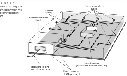
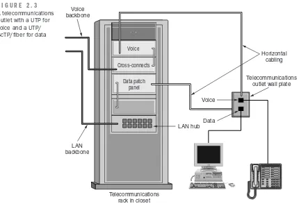
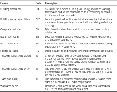
2.1 Structured Cabling and Standardization
This subsection explains the concept of structured cabling and its significance in creating a reliable network infrastructure. It outlines the benefits of standardization, including interoperability, scalability, and ease of maintenance. The discussion includes an overview of the components of structured cabling systems, emphasizing how they contribute to efficient data transmission and overall network performance.
2.2 Standards and Specifying Organizations
This subsection provides an overview of the key organizations involved in developing cabling standards, including ANSI, TIA, and EIA. It discusses their roles in establishing guidelines that ensure quality and performance in cabling systems. The importance of staying updated with these standards is emphasized for professionals involved in network design and implementation.
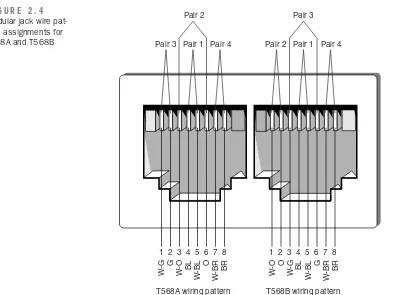
2.3 ANSI/TIA/EIA-568-B Cabling Standard
This subsection details the ANSI/TIA/EIA-568-B standard, which outlines the requirements for commercial building telecommunications cabling. It covers the standard's purpose, scope, and the subsystems of a structured cabling system. The significance of adhering to these specifications in ensuring optimal performance and compliance with industry best practices is highlighted.
Referensi Dokumen
- The Siemon Company
- Computer Training Academy