INTERNAL EROSION DURING SOIL PIPEFLOW:
STATE OF THE SCIENCE FOR EXPERIMENTAL AND
NUMERICAL ANALYSIS
G. V. Wilson, J. L. Nieber, R. C. Sidle, G. A. Fox
ABSTRACT.Many field observations have led to speculation on the role of piping in embankment failures, landslides, and gully erosion. However, there has not been a consensus on the subsurface flow and erosion processes involved, and incon-sistent use of terms have exacerbated the problem. One such piping process that has been the focus in numerous field ob-servations, but with very limited mechanistic experimental work, is flow through a discrete macropore or soil pipe. Ques-tions exist as to the condiQues-tions under which preferential flow through soil pipes results in internal erosion, stabilizes hillslopes by acting as drains, destabilizes hillslopes via pore-pressure buildups, and results in gully formation or refor-mation of filled-in ephemeral gullies. The objectives of this article are to review discrepancies in terminology in order to represent the piping processes better, to highlight past experimental work on the specific processes of soil pipeflow and in-ternal erosion, and to assess the state-of-the-art modeling of pipeflow and inin-ternal erosion. The studies reviewed include those that examined the process of slope stability as affected by the clogging of soil pipes, the process of gullies forming due to mass failures caused by flow into discontinuous soil pipes, and the process of gully initiation by tunnel collapse due to pipes enlarging by internal erosion. In some of these studies, the soil pipes were simulated with perforated tubes placed in the soil, while in others the soil pipes were formed from the soil itself. Analytical solutions of the excess shear stress equation have been applied to experimental data of internal erosion of soil pipes to calculate critical shear stress and erodibility properties of soils. The most common numerical models for pipeflow have been based on Richards’ equation, with the soil pipe treated as a highly conductive porous medium instead of a void. Incorporating internal erosion into such models has proven complicated due to enlargement of the pipe with time, turbulent flow, and episodic clogging of soil pipes. These studies and modeling approaches are described, and gaps in our understanding of pipeflow and internal ero-sion processes and our ability to model these processes are identified, along with recommendations for future research. Keywords. Ephemeral gully erosion, Erodibility, Internal erosion, Landslides, Pipeflow, Soil pipes.
any of the worst-case scenarios of soil ero-sion, e.g., dam and levee failures (Foster et al., 2000), landslides and debris flows (Uchida et al., 2001), streambank failures (Wilson et al., 2007), gully erosion (Faulkner, 2006), and
ephemeral gully erosion (Wilson, 2011), are attributed to piping. In an extensive review, Foster et al. (2000) found that 46% of dam failures were caused at least in part by piping. Jones et al. (1997) surveyed 74 basins in Britain and found that 30% were susceptible to piping. Pierson (1983) reported the propensity of landslide headscarps to contain a soil pipe, suggesting a cause-and-effect relationship. To our knowledge, no survey has determined what percentage of landslides or gullies have been caused by piping. This lack of information is partially due to the fact that development of these features removes the evidence of their origin, and/or the failed material covers up the evidence of piping (Hagerty, 1991a).
Despite the wealth of research on piping phenomena, there is little consensus on exactly what constitutes piping; many terms have been used, sometimes incorrectly, to de-scribe the various processes involved. For example, heave (boil), sapping, backwards erosion, seepage erosion, tunnel-ing (or juggtunnel-ing), suffusion, pipeflow, and internal erosion are just a few of the terms used to describe piping. As pointed out by Richards and Reddy (2007), “practicing engineers lump these definitions under the generic term piping” and geomorphologists and hydrologists tend to use some of the Submitted for review in February 2012 as manuscript number
SW 9621; approved for publication by the Soil & Water Division of ASABE in August 2012. Presented at the 2011 Symposium on Erosion and Landscape Evolution (ISELE) as Paper No. 11048.
This document has been reviewed in accordance with U.S. Environ-mental Protection Agency policy and approved for publication. The USDA is an equal opportunity employer and provider.
The authors are Glenn V. Wilson, ASABE Member, Soil Physicist and Research Hydrologist, USDA-ARS National Sedimentation Laborato-ry, Watershed Physical Processes Research Unit, Oxford Mississippi; John L. Nieber, ASABE Member, Professor, Department of Bioproducts and Biosystems Engineering, University of Minnesota, St. Paul, Minnesota;
Roy C. Sidle, Supervisory Physical Scientist and Division Director, U.S. EPA Ecosystems Research Division, Athens, Georgia; and Garey A. Fox, ASABE Member, Associate Professor and Orville L. and Helen L. Bu-chanan Chair, Department of Biosystems and Agricultural Engineering, Oklahoma State University, Stillwater, Oklahoma. Corresponding au-thor: Glenn V. Wilson, USDA-ARS National Sedimentation Laboratory, Watershed Physical Processes Research Unit, P.O. Box 1157, 598 McElroy Drive, Oxford, MS 38655; phone: 662-232-2927; e-mail: [email protected].
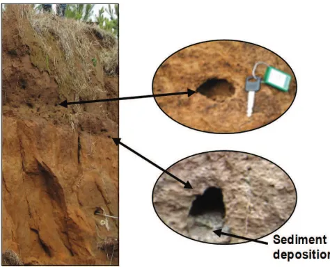
same terms as engineers but to describe different processes. Most often, engineers think of piping as seepage through a permeable layer below an “impermeable” barrier or em-bankment, with the resulting uplift of the granular material eroded out of the flow path on the backside of the barrier forming a dike of sediment around the boil in a process of-ten termed heave. Hagerty (1991a) proposed a distinction between piping and sapping, with sapping described as seepage that entrains particles in the exfiltrating flow over an extensive area, thereby resulting in cavities in the ex-posed face. Richards and Reddy (2007) used the term backwards erosion for particles being “progressively dis-lodged from the soil matrix through tractive forces pro-duced by intergranular seeping water.” They further ex-plained that backwards erosion forms a “bridged opening” at the exit point that tends to grow into the embankment as erosion continues. Thus, backwards erosion is the same as the term sapping used by Hagerty (1991a) and similar to the term “seepage erosion” used by Dunne (1990) and oth-ers (Fox et al., 2006; Wilson et al., 2007) to describe under-cutting of streambanks (fig. 1) by particle entrainment in seepage exfiltrating the banks. Fox and Wilson (2010) pro-posed that sapping refer to the mass failure or slumping re-sulting from undercutting of an embankment by seepage erosion.
Hagerty (1991a), Richards and Reddy (2007), and Fox and Wilson (2010) agree that seepage erosion is distinctly different from internal erosion, which is erosion of the walls of a discrete preferential flow path, such as the struc-tural or biological voids illustrated in figure 2. Some use in-ternal erosion to refer to the translocation of fines (clays) through the soil matrix (Reddi et al., 2000), but most often this distinctly different process is referred to as suffusion (Richards and Reddy, 2007). Hagerty (1991a) used the de-scription by Mears (1968) of “subterranean erosion initiat-ed by percolating waters which remove solid particles... to produce tubular underground conduits” as the definition of piping. In general, geomorphologists and hydrologists refer
to piping as flow through a discrete macropore or soil pipe (Jones, 1987; Chappell, 2010), which Dunne (1990) and Bryan and Harvey (1985) called tunnel flow, and the asso-ciated erosion as internal erosion. Fox and Wilson (2010) and Wilson (2011) proposed that flow through a discrete conduit should be distinguished from the general term “pip-ing” by its specific feature of “pipeflow” and the resulting erosion inside the soil pipe as internal erosion. Generally, soil pipes are taken to be macropores that are parallel to the slope (Kitahara, 1989; Terajima and Sakura, 1993; Weiler and McDonnell, 2007; Sharma et al., 2010). These soil pipes can be supplied with water from the surrounding sat-urated soil (Jones, 1981; Sklash et al., 1996) and/or by more-or-less vertical macropores that route water from sur-face runoff to form a preferential flow network (Sidle et al.,
Figure 1. Streambank used by Midgley et al. (2012) to study seepage erosion. Subsurface flows at locations indicated by arrows entrain particles and lead to undercuts in the bank face as indicated by (a) and (c), which are >50 cm wide. Undercutting at these bank locations subsequently leads to bank failures of the material above, which partially fills in the undercut, as indicated by (b) and (d) for the two respective locations, and temporarily provides self-healing of the seeps.
2001; Chappell, 2010). From the review by Jarvis (2007), it is clear that there has been a large body of research on macropore flow, i.e., pipeflow, and the number of publica-tions is increasing exponentially; however, as pointed out by Wilson (2009), very little of this work has dealt with erosion associated with pipeflow.
In contrast, banks or earthen embankments that are un-dercut by seepage erosion may have internal erosion occur-ring due to pipeflow, without being visible from the soil surface. Swanson et al. (1989) and Faulkner (2006) pro-posed that internal erosion can occur undetected until a ma-ture gully is suddenly formed by tunnel collapse. Pipe col-lapses are often seen on landscapes (Verachtert et al., 2010; Zhang and Wilson, 2012), thereby providing evidence after the fact that internal erosion by pipeflow had been occur-ring below ground. This process is very active in the Loess Plateau of China, where pipe collapses initiate gullies in silty soils (Sidle, 2006). Internal erosion can lead to breach-ing of embankments when the tunnel collapses (Hanson et al., 2010). These collapses can be mistakenly associated with convergent overland flow (gullies) and overtopping (embankment breaching).
Hydrogeologists working on landslides and debris flows generally attribute such phenomena to pipeflow; however, it is not clear as to how pipeflow functions to trigger these massive erosion events. Pierson (1983) suggested that soil pipes serve as natural drains of hillslopes, thereby increas-ing hillslope stability, which was supported by Sidle et al. (2006). However, Pierson (1983) also provided field obser-vations and experimental evidence suggesting that closed or clogged soil pipes can cause hillslope instability. If the transmission rate of water through a soil pipe is less than the rate of water entry into the pipe, an increase in pore wa-ter pressure will occur that could trigger a landslide. It has been speculated that internal erosion of soil pipes on steep forested hillslopes can result in clogging of the pipes, and there is some evidence of this from the dye tracer study of Anderson et al. (2009). The closure of pipes is assumed to cause sudden pressure buildups that initiate slope failure (Pierson, 1983; Brand et al., 1986; Uchida et al., 2001; Kosugi et al., 2004). The same processes may occur in streambanks and earthen embankments, but experimental measurements to confirm this hypothesis are lacking.
The objectives of this article are to (1) review the exper-imental and numerical approaches used to understand and quantify pipeflow and internal erosion and (2) identify knowledge gaps where future research efforts could be tar-geted. Here, piping is taken to be flow through a soil pipe, and a soil pipe is taken to be a macropore that has been en-larged by internal erosion, i.e., detachment of particles and aggregates along the soil pipe walls that is transported out of the soil through the soil pipe.
EXPERIMENTAL APPROACHES
SOIL PIPEFLOWMost conclusions regarding the role of pipeflow in soil erosion are based on field observations and inferences from landslides, debris flows, and gully formations. One of the
earliest geological assessments of piping was by Fletcher and Carroll (1949), who noted that “roughly 30% of the land has been lost by (piping)” in southern Arizona and de-scribed conditions under which pipeflow occurred. Leopold and Miller (1956) noted that “collapse of gully walls is greatly facilitated by piping or tunnels” and “only a small proportion of total flow in a gully reaches the gully channel by direct overpour” since “piping tunnels... deliver the bulk of the discharge.” Jones (1981) was one of the first to pro-vide general observations of the geologic context in which pipes are found and their spatial distribution, albeit in peat soils, which are prone to formation of large piping systems. Several studies have provided quantitative assessments of pipeflow rates and/or their spatial distributions (Smart and Wilson, 1984; Jones, 1987; Kitahara et al., 1989; Swanson et al., 1989; Ziemer, 1992; Torri et al., 1994; Uchida et al., 2001). Ziemer (1992) measured pipeflow by driving circu-lar-shaped metal flashing into the trench wall around a soil pipe. Flow rates were monitored in collection vessels using pressure transducers. Several investigators have used trac-ers to measure pipeflow rates and their spatial distribution (Jones, 1982; Mosley, 1982; Smart and Wilson, 1984). In contrast, Sklash et al. (1996) used natural tracers, i.e., iso-topic signatures of pipeflow, groundwater, and rainwater, to determine contributions of old water and new water to pipeflow. They found that most of the flow in pipes during and following rainfall events was pre-event water, i.e., old water.
Few studies have conducted experiments in which soil pipeflow was manipulated. Smart and Wilson (1984) con-ducted pump injections into pipe openings and monitored downgradient pipeflow to obtain pipeflow velocities from measured flow discharges and tracer travel times. Pierson (1983) performed the first reported laboratory study of flow in a hillslope containing a soil pipe. The hillslope was modeled by a sloping (50 cm high × 160 cm long) Hele-Shaw chamber with a soil pipe. The Hele-Hele-Shaw chamber consisted of two parallel, vertically erected, plates of per-spex (spaced 3 mm apart), with the void between them simulating the hillslope’s porous media. The soil pipe was simulated by cutting out a 60 cm length of the chamber and attaching an adjacent chamber to the backside of the plate to allow inflow and/or outflow of the chamber, i.e., an arti-ficial soil pipe. The artiarti-ficial soil pipe did not run the entire length of the chamber but only for a portion of the upper section, thereby mimicking a closed-ended pipe. Oil was used to simulate water flow through the hillslope under varying slope and pipe conditions. The study demonstrated that a closed-ended pipe could generate significant local pore pressures, suggesting that the presence of such pipes on a hillslope could lead to instability of the slope (Pierson, 1983).
100 cm long × 60 cm wide × 40 cm deep sand bed posi-tioned with a 12.8% slope. The upstream end of the artifi-cial soil pipe was closed, so water entered the pipe via seepage through the adjacent sand. Flow through the sand bed was established under a constant head at the upslope end, and outflow was partitioned between matrix flow and pipeflow, while piezometers measured soil water pressures.
Kosugi et al. (2004) further investigated the issue of pipe clogging associated with landslides. Instead of simu-lating clogging by pipe roughness, they performed a series of experiments that included a sand tank with no pipes pre-sent, a sand tank with open pipes, and a sand tank with closed (discontinuous) pipes. For the two cases with pipes present, they installed three parallel 1.0 cm diameter pipes, spaced 1.8 cm apart between centers, each positioned 1 cm above the bottom of a 70 cm long × 7.3 cm wide × 10 cm deep sand bed (fig. 4). All artificial soil pipes were 30 cm long, sealed (closed) at the upstream end, and made of per-forated acrylic pipe wrapped in cotton cloth. Tests with the open, i.e., non-clogged, pipes were conducted by extending the pipe outlets out of the sand bed, while tests with the
closed pipes terminated in the sand bed 15 cm upslope from the sand bed’s outflow face.
Wilson et al. (2008) conducted similar laboratory studies to address the role of closed-ended soil pipes in forming ephemeral gullies. Their experimental design was based on field observations of flow rates and sediment concentra-tions for a 3 cm diameter natural soil pipe at the head of an ephemeral gully that was eroded down to a fragipan (Wil-son et al., 2006). The ephemeral gully was known to occur in the same location periodically, but each time it was filled in by tillage, leaving the natural soil pipe buried and dis-continuous through the landscape. The laboratory experi-ments were conducted in a 150 cm long × 100 cm wide ×
15 cm deep soil bed with a 5% slope (fig. 5). A discontinu-ous artificial soil pipe was simulated by placing a 2 cm di-ameter porous irrigation tube (i.e., soaker hose) 50 cm into the soil bed from the upper end. The artificial soil pipe was placed in the topsoil (silt loam) immediately above a 5 cm thick water-restricting layer (silty clay loam). Tensiometers at the interface of the restrictive layer and topsoil measured soil water pressures downslope of the pipe. Wilson et al. (2008) conducted experiments under two constant heads on the upper end of the closed-ended pipe, with and without rainfall on the bed surface.
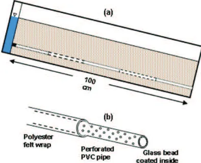
Figure 3. Experimental setup used by Sidle et al. (1995) with a single artificial soil pipe that was continuous through a sand bed but closed at the upper end near the water reservoir. The artificial soil pipe (b) was a perforated PVC pipe coated on the inside with glass beads. Each of the five sections of pipe in the sand bed (a) had different-sized beads coating the interior.
Figure 4. Experimental setup used by Kosugi et al. (2004) illustrating (a) sand beds with (b) three parallel artificial soil pipes located either as closed pipes (within the sand bed but not connected to either the upper or lower water reservoir) or open pipes (closed at the upper end but open at the lower end to a water reservoir).
INTERNAL EROSION
While the laboratory studies discussed in the previous section addressed the role of pipeflow in mass failures, landslides, and gullies, they did not address the process of internal erosion. As noted earlier, internal erosion often de-scribes suffusion or translocation of fines; however, internal erosion is more widely understood to represent the process of particle detachment from the walls of a preferential flow path, i.e., soil pipe. This form of internal erosion has been characterized experimentally for decades by the pinhole erosion test (MacIver and Hale, 1970), a test originally de-veloped as a qualitative method for identifying dispersive soils. Flow is established through a compacted soil core with a small hole drilled through the center. Turbidity of the outflow is measured along with the final hole diameter to classify the dispersive nature of the material. Wan and Fell (2004) extended this method into a quantitative procedure for measuring internal erosion, called the hole erosion test (HET), by measuring changes in flow rate with time to back-calculate changes in the pipe diameter and thus the in-ternal erosion (fig. 6).
Wan and Fell (2004) also developed the slot erosion test (SET) for quantifying internal erosion. The SET involves a 100 cm long × 15 cm wide × 10 cm deep soil bed with a 2.2 mm high × 10 mm deep slot, i.e., soil pipe, cut along the entire length of its outer edge and viewable through the plex-iglass wall (fig. 7). Changes in the slot (soil pipe) size are measured with time by digital imaging. The HET and SET allow calculation of the soil erodibility and critical shear stress, more appropriately termed initial shear stress by the
Figure 6. (a) Diagram of the hole erosion test (HET) illustrating the soil core with a 6 mm diameter pinhole (i.e., soil pipe) created through the core and wedged between upstream and downstream gravel-filled chambers for controlling the pieziometric conditions of the flow; (b) circular soil pipe with initial 6 mm pinhole (solid circle) that en-larges with time (dotted circle).
authors. They used the negative log of the soil erodibility as an erosion rate index to characterize the internal erosion of materials.Wilson (2009) studied internal erosion of soil pipes in silt loam loess material by conducting laboratory experiments with 150 cm long × 100 cm wide × 15 cm deep soil beds held at 15% slope (fig. 8). A soil pipe was created by packing soil around a 1 cm diameter rod that was subsequently removed by pulling the rod from the soil bed. The soil pipe was created immediately above a water-restricting layer. Tensiometers were installed on each side of the soil pipe and at two depths immediately above the soil pipe (fig. 8 inset). Experiments were conducted with and without rainfall and with two different steady-state flow rates into the soil pipe. Wilson (2011) modified the experimental setup used in 2009 by applying a constant head on soil pipes of 2, 4, 6, 8, and 10 mm initial diameters (fig. 9). Additionally, there was no water-restricting layer, so the soil pipe was positioned 60 mm above the plexiglass bottom in a uniform soil bed.
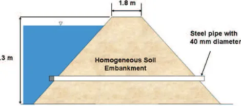
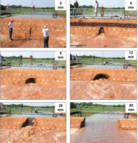
Hanson et al. (2010) conducted a large-scale test of inter-nal erosion by pipeflow through an earthen embankment (fig. 10). The embankment was 1.3 m high, 1.8 m across the level surface, and 9.6 m wide at the base (slope of 3H:1V). The soil pipe was created by packing the embankment around a 40 mm steel pipe, with the upstream end of the pipe capped. The experimental facility enabled the simulation of a large water reservoir on the embankment. Once a constant water level was established on the embankment, the steel pipe was pulled out of the downslope side, pipeflow was record-ed, and internal erosion was tracked by video cameras. The resulting internal erosion appeared as backwards erosion (or seepage erosion) at the embankment face but was, in fact, a result of internal erosion of the soil pipe created through the embankment (fig. 11). Different soils with a range of erodibility characteristics were tested after careful characterization of the materials.
KNOWLEDGE GAINED AND KNOWLEDGE GAPS
There has been a fairly extensive body of work on measuring pipeflow rates and characterizing soil pipes in situ but a limited amount of experimental work under con-trolled conditions, and the experimental work done to date has used widely varying techniques. A summary of the most relevant work is presented in table 1. The inaugural work on pipeflow by Pierson (1983) in a Hele-Shaw simu-
Figure 8. Experimental setup used by Wilson (2009) to study flow and internal erosion through continuous soil pipes under steady-state inflow, with and without rainfall on the soil bed. Tensiometers were located at 25, 50, and 75 cm in the arrangement shown in the inset. The soil bed consisted of a water-restrictive base layer with loess topsoil above. The soil pipe was positioned immediately above the restrictive layer.
Figure 9. Experimental setup used by Wilson (2011) to study flow and internal erosion through continuous soil pipes under constant head conditions: (a) side view of single layered soil bed, and (b) front view showing position of tensiometer cups (indicated by solid dots) relative to soil pipe (open circle).
lated porous medium suggested that high pore pressures, sufficient to trigger landslides, could result from closed pipes. Sidle et al. (1995) found that pipe sections with high internal roughness were associated with increased soil wa-ter pressures. Their work showed a proof of principle that clogging of soil pipes could result in the pressure increases commonly assumed to cause landslides. Subsequent work by Kosugi et al. (2004) corroborated these findings by showing that soil water pressures adjacent to closed-ended pipes were greater than cases without pipes or with open-ended pipes, and they proposed that the increased pressures could trigger landslides. This work also supported the theo-ry (Sidle et al., 2006) that soil pipes could stabilize
hill-slopes by providing drainage, since open pipes tended to decrease the soil water pressure compared to the case with no soil pipes. Both studies used artificial (PVC and acrylic) pipes in sand tanks. Wilson et al. (2007) also used an artifi-cial pipe but tried to simulate field conditions in which an open-ended pipe at the head of an ephemeral gully and im-mediately above a fragipan layer is closed (i.e., becomes discontinuous) when the gully is filled in by tillage. They used a porous soaker hose to represent the soil pipe in a bed of silt loam loess soil over compacted silty clay loam soil to mimic the water-restrictive layer. They observed seepage from the soil bed immediately above the restrictive layer, while tensiometers 5 cm from the face exhibited negative
values, i.e., unsaturated conditions. The combination of rainfall with soil pipeflow resulted in sudden mass failures that they postulated could re-establish ephemeral gullies in the same locations.
While these studies gave new insights into pipeflow mechanisms, they were limited in scope. Use of artificial pipes prevented the study of internal erosion and its impact on pipeflow and cataclysmic erosion events, e.g., landslides or gullies. More work needs to be done to understand pipe-flow mechanisms, such as:
• Determining how pipeflow is initiated and main-tained.
• Quantifying the transfer of water into soil pipes and from soil pipes into the soil matrix.
• Determining what soil and hydrologic conditions fos-ter pipeflow.
• Measuring soil water pressures within soil pipes dur-ing pipeflow as opposed to the adjacent soil.
Future studies should use created soil pipes, e.g., open-ings created in soil, or natural soil pipes under field condi-tions. Midgley et al. (2013) is the first to report in situ
measurements of pore water pressure buildups within a soil pipe due to pipe clogging. They created soil pipes in streambanks and plugged the ends to simulate pipe clog-ging while measuring pore water pressures within the pipe and in the soil adjacent to the clogged pipe.
Controlled experimental work on internal erosion has been based on created soil pipes. A summary of this work is presented in table 2. Wilson (2009) observed that flow through created soil pipes exhibited surges, despite steady inflow, due to internal erosion temporarily clogging soil pipes. Only minimal changes in soil water pressures in the soil adjacent to the soil pipe were associated with these surges in pipeflow. Wilson (2009) suspected that the mini-mal pressure response was due to hydraulic non-equilibrium between pressures within the soil pipe and pressures measured in the adjacent soil, and to clogging that occurred over a shorter period (10 to 20 s) than the ten-siometer reading interval (60 s). Soil pipes enlarged from 1 cm to >5 cm diameter, but tunnel collapse was not ob-served, which Wilson speculated was due to the imposed boundary condition on the pipe that did not allow increases in pipeflow rates as pipes enlarged. This was the first ex-perimental study to observe clogging of soil pipes by inter-nal erosion. However, soil water pressures within the soil pipes or immediately adjacent to clogged sections of the soil pipes were not measured.
Wilson (2011) also observed surges in pipeflow due to internal erosion clogging, with pipeflow rates rapidly in-creasing as soil pipes enlarged such that experiments had to be terminated due to the flow rate exceeding the inflow ca-pacity. Interestingly, the 2 and 4 mm diameter pipes did not exhibit pipeflow since these small soil pipes closed due to
Table 1. Characteristics of experimental studies of pipeflow.
Reference Porous Media Pipe Description Boundary Condition Major Findings Pierson,
1983
Two vertical, parallel perspex
plates
Closed artificial pipe (planar void between perspex plates)
Constant head of hydraulic oil on void between plates
Local soil water pressures increase inside closed pipes, which could trigger landslides.
Sidle et al., 1995
Sand bed (beach sand)
Open-ended artificial pipe (perforated PVC tubing, five sections with different internal roughness)
Constant head of water on upper end of sand bed
Log-linear relation between pipeflow with piezometric head and with matrix flow; soil water pressures higher adjacent to restrictive (high roughness) pipe sections.
Kosugi artificial pipes in triplicate (three perforated acrylic tubes)
Constant head of water on upper and lower end of sand bed
Open pipes lowered the soil water pressure and could increase slope stability; soil water pressure increases at lower end of closed pipes could decrease stability.
Wilson
Constant head of water on pipe inlet; rainfall on soil surface
Hydraulic non-equilibrium with seepage occurring under negative soil water pressures 1 cm above restrictive layer; pipeflow with rainfall produced sudden mass wasting.
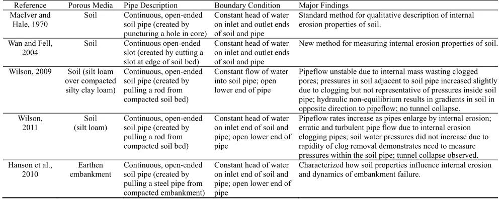
Table 2. Characteristics of experimental studies on pipeflow with internal erosion.
Reference Porous Media Pipe Description Boundary Condition Major Findings MacIver and
Hale, 1970
Soil Continuous, open-ended soil pipe (created by
puncturing a hole in core)
Constant head of water on inlet and outlet ends of soil and pipe
Standard method for qualitative description of internal erosion properties of soil.
Wan and Fell, 2004
Soil Continuous open-ended slot (created by cutting a slot at edge of soil bed)
Constant head of water on inlet and outlet ends of soil and pipe
New method for measuring internal erosion properties of soil.
Wilson, 2009 Soil (silt loam over compacted silty clay loam)
Continuous, open-ended soil pipe (created by pulling a rod from compacted soil bed)
Constant flow of water into soil pipe; open lower end of pipe
Pipeflow unstable due to internal mass wasting clogged pores; pressures in soil adjacent to soil pipe increased slightly due to clogging but not representative of pressures inside soil pipe; hydraulic non-equilibrium results in gradients in soil in opposite direction to pipeflow; no tunnel collapse.
Wilson, 2011
Soil (silt loam)
Continuous, open-ended soil pipe (created by pulling a rod from compacted soil bed)
Constant head of water on inlet end of soil and pipe; open lower end of pipe
Pipeflow rates increase as pipes enlarge by internal erosion; erratic and turbulent pipe flow due to internal erosion clogging pipes; soil water pressures did not increase due to rapidity of clog removal demonstrates need to measure pressures within the soil pipe; tunnel collapse observed. Hanson et al.,
2010
Earthen embankment
Continuous, open-ended soil pipe (created by pulling a steel pipe from compacted embankment)
Constant head of water on inlet end of soil and pipe; open lower end of pipe
internal erosion as soon as flow was established. While soil water pressures did not exhibit increases associated with the clogging of the pipes, this was likely the result of tensi-ometers not being positioned inside or close enough to the soil pipe and to how rapid the clogs were removed (flushed out). Wilson (2011) extended the analytical methods of Wan and Fell (2004) for this experimental setup to obtain soil erodibility and critical shear stress values for internal erosion. Wilson (2011) noted that tunnel collapse occurred within minutes of flow initiation and reasoned that such pipe collapse features in fields would be misinterpreted as being caused by surface runoff unless observations were made during this critical stage of the erosion event. Hagerty (1991b) discussed the difficulty of recognizing pipeflow (piping) as the cause of erosion, since direct evidence, e.g, “water emerging from a soil face” is rarely encountered. Hagerty (1991b) also concluded that the difficulty was be-cause of the complexity of the mechanisms, in that interac-tions with other processes tended to mask piping or remove features that are indicative of piping.
Unlike the previous work that addressed pipeflow dy-namics in hillslopes and internal erosion associated with gullies, the work by Hanson et al. (2010) was the first con-trolled experiment on internal erosion of soil pipes associ-ated with embankment failures. They observed rapid en-largement of the soil pipe at the downslope side of the embankment. For the materials with an erodibility of 100 cm3 N-1 s-1, tunnel collapse was observed after just 13 min. Following pipe collapse, the breach widened rapid-ly by sidewall mass failures. For the materials with an erod-ibility of 0.1 cm3 N-1 s-1, the pipe slowly expanded by inter-nal erosion until the experiment was terminated after 72 h. This work documented the vulnerability of embankments to pipeflow, the critical role of soil erodibility characteristics, and the importance of other soil properties and engineered placement.
Future work needs to be conducted under field condi-tions for a variety of soils and hydrologic condicondi-tions. Such research could include created or natural soil pipes but should also provide observations of soil water pressures within the soil pipes and in the soil immediately adjacent to the soil pipe at locations where clogging occurs, such as the work by Midgley et al. (2013). One of the interesting ob-servations by Wilson (2009) was hydraulic gradients, measured in the soil matrix, in the opposite direction of pipeflow. This has been observed in field conditions (DeVries and Chow, 1978; Simon and Wells, 2006) and as-sumed to be due to macropores causing bypass flow. The hydraulic non-equilibrium between the water pressures in-side the soil pipe and those in the adjacent soil indicate a need to make observations within the soil pipe if the con-cept of mass failures, e.g., landslides, being caused by pres-sure buildups due to pipe clogging is to be confirmed ex-perimentally. Improved techniques need to be developed for real-time quantification of the pipe enlargement by in-ternal erosion, such as insertion of micro-cameras or inter-nal laser scanning.
NUMERICAL APPROACHES
MODELING PIPEFLOWConsiderably more work has been conducted on model-ing macropore flow than pipeflow, but the processes are similar and the approaches are applicable. Gerke (2006) re-viewed the deterministic approaches for modeling preferen-tial flow and transport, including macropore flow. The most common approach is the application of Richards’ equation:
xx yy and t is time. Richards’ equation can be applied to the soil pipe alone (mobile-immobile approach; van Genuchten and Wierenga, 1976); to flow through both the soil matrix and the soil pipe (dual-permeability approach; Gerke and van Genuchten, 1993); to flow through soil pipes, smaller inter-connected soil pipes, and the soil matrix (multiregion flow approach; Gwo et al., 1995); or to flow through the soil ma-trix with the soil pipe treated as an internal boundary condi-tion (Barcelo and Nieber, 1981, 1982; Tsutsumi et al., 2005).
Several published studies (Kosugi et al., 2004; Nieber et al., 2006; Akay et al., 2008; Nieber and Sidle, 2010; Shar-ma et al., 2010; Lu and Wilson, 2012) have applied Rich-ards’ equation to pipeflow by treating the soil pipe as a highly conductive porous medium, rather than a linear void, and manipulating the hydraulic properties of the pipe re-gion. Sharma et al. (2010) assumed the hydraulic conduc-tivity of the soil pipe to be 20 times that of the soil matrix, whereas Lu and Wilson (2012) and Akay et al. (2008) ob-tained calibrated values that were three and four orders of magnitude higher, respectively. Nieber et al. (2006) and Nieber and Sidle (2010) assumed that the saturated hydrau-lic conductivity of the soil pipe was six orders of magnitude higher than the matrix in simulations with multiple discon-nected soil pipes within porous media; this addressed the concept of self-organization of preferential flow paths when soil water pressures exceed a threshold beyond which soil pipes become hydraulically active and inter-connected. In contrast, a single discontinuous soil pipe, i.e., not connect-ed to the water source, was simulatconnect-ed by Sharma et al. (2010), while a single continuous soil pipe connected to a dynamic water reservoir was simulated by Lu and Wilson (2012). In these Richards’ equation approaches to modeling pipeflow, flow can occur from the soil matrix into the soil pipe region or from the soil pipe to the soil matrix. Howev-er, the soil pipe region always had a fixed geometry that did not account for the dynamic geometry of the soil pipe as a result of internal erosion.
by Kirkham (1949) that assumes the pipe is flowing full. In their formulation, the flow could only enter the pipe but not flow out of the pipe into the surrounding soil matrix. Simi-lar to Barcelo and Nieber (1981), Tsutsumi et al. (2005) simulated the soil pipe as a single line of nodes, of negligi-ble volume, with boundary conditions to simulate either no pipe flow, a partially filled pipe, or full pipe flow.
MODELING INTERNAL EROSION
While the Richards’ equation approaches have been used extensively for solute transport modeling, they have yet to be extended to sediment transport modeling. The rate of production of sediment into the fluid stream within the pipe is usually expressed as:
(
)
bs s c
q =k τ − τ (2)
where qs is the sediment transport rate (kg s-1 m-2), ks is the
erodibility coefficient (s m-1), which differs from the erodi-bility expression of Hanson et al. (2010) by the bulk densi-ty, τ is the wall shear stress (N m-2), and τc is the critical
shear stress (N m-2). Equation 2 typically assumes a linear relationship (b = 1) between applied shear stress (τ) and sediment transport rate once τc has been exceeded. Wan and
Fell (2004) applied this analytical approach to HET and SET data to calculate critical shear stress and erodibility. Wilson (2011) used a modified form of their approach to calculate τc and ks from soil pipes in the middle of a sloping
soil bed.
Sediment from soil pipes is derived from two different mechanisms. One is the particle detachment that occurs along the walls of a pipe as a result of seepage forces in which gradients can be from soil to pipe or from pipe to soil. The other mechanism is the detachment from the walls of a pipe as a result of shear forces on the walls from water flowing through the soil pipe. For this second source, the pipe can be flowing either full or partially full. The fluid shear stress on the wall of a soil pipe as a result of water flow through the pipe under full-flow conditions can be ex-pressed as: mass balance equation for pipe wall erosion and suspended sediment transport facilitates calculation of the rate at which particles are lost from the walls of the soil pipe, and therefore calculation of the change in pipe cross-section, given by:
sediment loss calculation creates a feedback to the soil pipe in that the mean velocity increases as the pipe enlarges, which then increases the erosion rate and rate of enlarge-ment.
INTEGRATED PIPEFLOW AND INTERNAL
EROSION MODELS
Bonelli et al. (2006) used two-phase flow equations (wa-ter-particle mixture and particles alone) with interface ero-sion for modeling flow and eroero-sion in a soil pipe of length
L and radius R with initial value Ro. The soil was assumed
to be homogeneous. The erosion component was based on predicted tangential shear stresses on the pipe wall using threshold equations in equation 2. As erosion occurs, a mass flux crosses the time- and length-dependent interface, and the current interface transitions from solid-like to fluid-like behavior (Bonelli et al., 2006). The model predicts the radius, R(t), and mean longitudinal velocity, V(t), of the
stress due to the hydraulic gradient based on inflow (pin)
and outflow pressures (pout), t is time, and:
and ks is the erodibility coefficient. This proposed model
was shown to conform to experimental data from HETs on nine different soils with a wide range of erodibility coeffi-cients and critical shear stresses. Additional research is needed for building on this proposed framework in terms of the transport of high sediment concentration fluids (versus dilute concentration) in soil pipes and turbulent flow condi-tions. Modifications of the model may be necessary to con-sider this hyper-concentrated, turbulent flow, which can lead to soil clogging.
KNOWLEDGE GAINED AND KNOWLEDGE GAPS
Nieber and Sidle (2010) used the Richards’ equation modeling approach to show that subsurface flow is directed through soil pipes in the saturated portion of a hillslope but bypasses soil pipes in drier regions. Simulations by Sharma et al. (2010) and Lu and Wilson (2012) corroborated the dual role of soil pipes in draining a saturated hillslope as well as creating soil water pressure increases in a hillslope. Problems with this approach are that (1) pipeflow is often turbulent; (2) there is difficulty in describing the hydraulic water retention, θ(h), and hydraulic conductivity, K(h), properties for the pipe region; (3) soil pipes are not always fully saturated (flowing full); and (4) dynamic changes oc-cur in the soil pipe geometry due to internal erosion.
or small constant heads are applied. There is a significant body of work on modeling (Escue and Cui, 2010) and ex-perimentally assessing (Kitoh, 1991; Li and Tomita, 1994) turbulent flow in rigid, straight, smooth-walled pipes, but no attempts have been made to apply these approaches to flow through soil pipes, which are obviously not straight, smooth, or rigid (i.e., internal erosion expands the soil pipe).
The most common approach for describing the water re-tention and hydraulic conductivity functions are the van Genuchten relationships (van Genuchten, 1980), although Tsutsumi et al. (2005) applied the Kosugi (1996) functions to soil pipeflow. These models were developed for a single flow region and therefore represent the soil matrix but not the soil matrix and soil pipe. Experimental and modeling techniques have been developed for describing the hydrau-lic function of dual and multiregion soils (Wilson et al., 1992; Mohanty et al., 1997; Zurmühl and Durner, 1998). These are continuum approaches in which pore regions are distinguished in the water retention curve and piecewise continuous models are then applied. An alternative that may be applicable to an individual soil pipe region is a unit step function in which the soil pipe is assumed to be either filled, and therefore conductive, or empty. The shortcoming with using this “Dirac delta” function approach is that con-vergence of iterative numerical solutions becomes more difficult to achieve when properties such as hydraulic con-ductivity change sharply.
An alternative to representing a soil pipe as a porous medium filled domain, and modeling the flow in that do-main with Richards’ equation, is to model the soil pipe as a void and prescribe boundary conditions along the pipe wall. This approach suffers from the problem of which boundary conditions to apply along the interface boundary of the void, given the dynamic nature of the flow and the fact that the pipe is not always filled with water. The approach is further complicated by the fact that it also requires that a mass balance be conducted on the water that enters and ex-its the void so as to know what flow conditions exist inside the void. When the soil pipe is treated as a porous medium filled domain and modeled using Richards’ equation, the is-sue of mass balance is taken into account. While Tsutsumi et al. (2005) treated the soil pipe as a line of connected nodes and not a void, they applied a combination of Di-richlet (static water pressure) conditions and seepage face conditions at the inlet and outlet of the soil pipe, respective-ly, and varying boundary conditions along the soil pipe de-pending upon the flow condition. For soil around a partially filled soil pipe, a Dirichlet boundary condition (h = 0) was imposed along the open channel portion, whereas a seepage face was assumed along the saturated portion. A Neumann boundary condition (i.e., prescribed flux) was imposed along the fully filled soil pipe. The challenge in modeling the interaction between the soil pipe and soil matrix is that the transient nature of the flow dynamics requires a priori
knowledge of the transient boundary conditions to apply along the pipe.
A major obstacle with any numerical solution approach to modeling pipeflow in the context of internal erosion is that the soil pipe enlarges with time. Thus, the geometry of
the highly conductive pipe region or void with boundary conditions on the pipe walls changes with time. A dynamic discretization approach that could adjust nodal spacing as the conductive region dimensions change would be advan-tageous, but what is needed is a dynamic flow domain. To model the case in which flow region boundaries change as a result of erosion, Chu Agor et al. (2008) modeled stream-bank failure by seepage erosion in which the dimension of the flow domain changed manually as seepage erosion of the conductive layer created an undercut in the streambank. To date, a dynamic flow domain approach has not been de-veloped for pipeflow modeling.
Given the paucity of experimental data on pipeflow ero-sion, it is not clear that the linear version of the excess shear stress is appropriate or whether the more general form with an exponent (b≠ 1) should be applied. Bonelli et al. (2006) was able to apply the excess shear stress equation with b = 1 to HETs, but it has not yet been applied to larg-er-scale laboratory and field studies. A more fundamentally based detachment model may be advantageous, compared to an excess shear stress formulation, for modeling internal erosion because of the ability to mechanistically incorpo-rate additional forces into the analysis. The excess shear stress formulation lacks mechanistic predictions of its pa-rameters for specific soil and hydraulic conditions. Using a fundamental detachment model, the Bonelli et al. (2006) framework should be integrated with Richards’ equation for flow through the soil matrix for modeling seepage forces between the soil matrix and pipe domains. Wilson (1993) proposed a fundamental detachment-based model for cohe-sive soils that predicted erosion rates, as well as excess shear stress formulations, based on two-dimensional soil parameters.
Incorporation of internal erosion in flow simulations to produce a sediment transport model for pipeflow erosion is complicated by several factors and processes that need to be incorporated into such a model: (1) the feedback mecha-nism of flow rate increases as internal erosion enlarges the pipe; (2) sediment concentrations can exceed the transport capacity of the pipeflow, resulting in clogging of the pipe, particularly at early stages of pipe development (when the pipe is small); and (3) internal erosion can occur as mass failures of aggregated material. The latter two factors can lead to the type of pulsating flows and pressure buildups and releases observed by Wilson (2011). Clearly, advances are needed in the ability to model the preferential flow, sed-iment detachment, internal mass failures, and sedsed-iment transport processes associated with internal erosion of soil pipes.
CONCLUSION
pipe-flow, and (3) suffusion. While Richards and Reddy (2007) are correct that “the term piping is describing a number of different phenomena,” it is not likely that engineers or hy-drogeologists will develop a “common language and under-standing of piping.” Thus, it is imperative that researchers carefully note how these terms are used in references and clearly articulate their meaning when using them. For a re-view of the seepage erosion or backward erosion forms of piping, see Fox and Wilson (2010), whereas this article re-viewed the terms used to describe piping in general and the work conducted to experimentally measure the pipeflow and internal erosion-specific forms of piping. A brief dis-cussion is given about modeling the pipeflow and internal erosion processes.
Field observations provide strong evidence that pipeflow and internal erosion are associated with embankment fail-ures, landslides, and gully formation, but experimental documentation is still lacking. Experiments under con-trolled laboratory conditions have provided the following state of knowledge:
• Open-ended soil pipes can provide drainage of hillslopes, thereby increasing their stability.
• Soil pipes can become clogged when pipeflow rates are sufficient to cause internal erosion.
• Flow into closed-ended or discontinuous soil pipes can foster mass wasting that reforms ephemeral gul-lies.
• Clogging by internal erosion results in surges and turbulent flow in soil pipes.
• Soil water pressures adjacent to soil pipes can in-crease due to clogging, but such soil water pressures are not representative of water pressures within soil pipes due to hydraulic non-equilibrium.
• Internal erosion can result in tunnel collapse.
It is clear that more research is needed on pipeflow and internal erosion. Future experimental efforts should address the following knowledge gaps:
• Develop non-destructive techniques to detect soil pipes in situ and monitor internal erosion and/or en-largement of soil pipes.
• Measure the rates of internal erosion associated with pipeflow under field conditions, whether using natu-ral or created soil pipes, and how these relate to soil properties.
• Measure, in laboratory and field conditions, water pressures within soil pipes in response to clogging.
• Quantify how water pressures measured in soil adja-cent to soil pipes relate to water pressures within soil pipes.
• Demonstrate that clogging of soil pipes can result in hillslope or bank failure and determine the requisite hydrogeological conditions for such clogging.
• Establish criteria or guidelines for assessing the sus-ceptibility of landscapes or embankments to failure by internal erosion due to pipeflow.
In addition to these experimental efforts, numerical analysis should verify the appropriateness of the linear ex-cess shear formulation for internal erosion and the benefits of more fundamental detachment-based models. Future
modeling efforts should apply turbulent flow dynamic models to pipeflow simulations, and existing pipeflow models need to incorporate internal erosion and sediment transport in their simulations.
ACKNOWLEDGEMENTS
The review and suggestions for improvement by Dr. Greg Hanson and Fran Rauschenberg are greatly appreciat-ed.
REFERENCES
Akay, O., G. A. Fox, and J. Simunek. 2008. Numerical simulation of flow dynamics during macropore-subsurface drain interaction using HYDRUS. Vadose Zone J. 7(3): 909-918. Anderson, A. E., M. Weiler, Y. Alila, and R. O. Hudson. 2009. Dye staining and excavation of a lateral preferential flow network. Hydrol. Earth Syst. Sci. 13(6): 935-944. Barcelo, M. D., and J. L. Nieber. 1981. Simulation of the
hydrology of natural pipes in a soil profile. ASAE Paper No. 812028. St. Joseph, Mich.: ASAE.
Barcelo, M. D., and J. L. Nieber. 1982. Influence of a soil pipe network on catchment hydrology. ASAE Paper No. 822027. St. Joseph, Mich.: ASAE.
Bonelli, S., O. Brivois, R. Borghi, and N. Benahmed. 2006. On the modelling of piping erosion. Comptes Rendu Mécanique 334(8-9): 555-559.
Brand, E. W., M. J. Dale, and J. M. Nash. 1986. Soil pipes and slope stability in Hong Kong. Qtly. J. Eng. Geol. and Hydrogeol. 19(3): 301-303.
Bryan, R. B., and L. E. Harvey. 1985. Observations on the geomorphic significance of tunnel erosion in a semi-arid ephemeral drainage system. Geografiska Annaler Series A 67(3-4): 257-272.
Chappell, N. A. 2010. Soil pipe distribution and hydrological functioning within the humid tropics: A synthesis. Hydrol. Proc. 24(12): 1567-1581.
Chu-Agor, M. L., G. V. Wilson, and G. A. Fox. 2008. Numerical modeling of bank instability by seepage erosion undercutting of layered streambanks. J. Hydrol. Eng. 13(12): 1133-1145. DeVries, J., and T. L. Chow. 1978. Hydrologic behavior of a
forested mountain soil in coastal British Columbia. Water Resour. Res. 14(5): 935-942.
Dunne, T. 1990. Hydrology, mechanics, and geomorphic implications of erosion by subsurface flow. In Groundwater Geomorphology: The Role of Subsurface Water in Earth-Surface Processes and Landforms, 11-28. C. G. Higgins and D. R. Coates, eds. GSA Special Paper 252. Boulder, Colo.: Geological Society of America.
Escue, A., and J. Cui. 2010. Comparison of turbulence models in simulating swirling pipe flows. Applied Math. Modelling 34(10): 2840-2849.
Faulkner, H. 2006. Piping hazard on collapsible and dispersive soils in Europe. In Soil Erosion in Europe, 537-562. J. Boardman and J. Poesen, eds. Chichester, U.K.: John Wiley and Sons, Ltd.
Fletcher, J. E., and P. H. Carroll. 1949. Some properties of soils associated with piping in southern Arizona. SSSA Proc. 13(C): 545-547.
Foster, M. A., R. Fell, and M. Spannangle. 2000. The statistics of embankment dam failures and accidents. Canadian Geotech. J. 37(5): 1000-1024.
research needs. Invited review. SSSA J. 74(3): 717-733. Fox, G. A., G. V. Wilson, R. K. Periketi, and R. F. Cullum. 2006.
Sediment transport model for seepage erosion of streambank sediment. J. Hydrol. Eng. 11(6): 603-611.
Fox, G. A., G. V. Wilson, A. Simon, E. Langendoen, O. Akay, and J. W. Fuchs. 2007. Measuring streambank erosion due to ground water seepage: Correlation to bank pore water pressure, precipitation, and stream stage. Earth Surface Proc. and Landforms 32(10): 1558-1573.
Gerke, H. H. 2006. Preferential flow descriptions for structured soils. J. Plant Nutr. Soil Sci. 169(3): 382-400.
Gerke, H. H., and M. Th. van Genuchten. 1993. A dual-porosity model for simulating the preferential movement of water and solutes in structure porous media. Water Resour. Res. 29(2): 305-319.
Gwo, J. P., P. M. Jardine, G. V. Wilson, and G. T. Yeh. 1995. A multi-pore-region concept to modeling mass transfer in subsurface media. J. Hydrol. 164(1-4): 217-237. Hagerty, D. J. 1991a. Piping/sapping erosion: I. Basic
considerations. J. Hydraul. Eng. 117(8): 991-1008. Hagerty, D. J. 1991b. Piping/sapping erosion: II.
Identification-diagnosis. J. Hydraul. Eng. 117(8): 1009-1025.
Hanson, G. J., R. D. Tejral, S. L. Hunt, and D. M. Temple. 2010. Internal erosion and impact of erosion resistance. Proc. 30th USSD Annual Meeting and Conf., 773-784. Denver, Colo.: U.S. Society on Dams.
Jarvis, N. J. 2007. A review of non-equilibrium water flow and solute transport in soil macropores: Principles, controlling factors, and consequences for water quality. European J. Soil Sci. 58(3): 523-546.
Jones, J. A. A. 1981. The Nature of Soil Piping: A Review of Research. BGRG Research Monograph 3. Norwich, U.K.: Geo Books.
Jones, J. A. A. 1982. Experimental studies of pipe hydrology. In Badlands Geomorphology and Piping, 355-370. R. B. Bryan and A. Yair, eds. Norwich, U.K.: Geo Books.
Jones, J. A. A. 1987. The effects of soil piping on contributing area and erosion patterns. Earth Surface Proc. and Landforms 12(3): 229-248.
Jones, J. A. A, J. M. Richardson, and H. J. Jacobs. 1997. Factors controlling the distribution of piping in Britain: A
reconnaissance. Geomorphology 20(3-4): 289-306.
Kirkham. D. 1949. Flow of ponded water into drain tubes in soil overlying an impervious layer. Trans. American Geophysical Union 30: 369-385.
Kitahara, H. 1989. Characteristics of pipe flow in a subsurface soil on a gentle slope: II. Hydraulic properties of pipes. J. Japanese Forestry Soc. 71: 317-322.
Kitoh, O. 1991. Experimental study of turbulent swirling flow in a straight pipe. J. Fluid Mech. 225: 445-479.
Kosugi, K. 1996. Lognormal distribution model for unsaturated soil hydraulic properties. Water Resour. Res. 32(9): 2697-2703. Kosugi, K., T. Uchida, and T. Mizuyama. 2004. Numerical
calculation of soil pipe flow and its effect on water dynamics in a slope. Hydrol. Proc. 18(4): 777-789.
Leopold, L. B., and J. P. Miller. 1956. Ephemeral streams, hydraulic factors, and their relation to the drainage net. USGS Professional Paper 282A. Reston, Va.: U.S. Geological Survey. Li, H., and Y. Tomita. 1994. Characteristics of swirling flow in a
circular pipe. J. Fluid Eng. 116(2): 370-373.
Lu, Z., and G. V. Wilson. 2012. Acoustic measurements of soil pipeflow and internal erosion. SSSA J. 76(3): 853-866. MacIver, B. N., and G. P. Hale. 1970. Engineering and Design:
Laboratory Soils Testing. Engineering Manual No. 1110-2-1906. Washington D.C.: U.S. Army Corps of Engineers. Mears, B., Jr. 1968. Piping. In Encyclopedia of Geomorphology,
840. R. W. Fairbridge, ed. Stroudsberg, Pa.: Hutchinson and Ross.
Midgley, T. L., G. A. Fox, G. V. Wilson, D. M. Heeren, E. Langendoen, and A. Simon. 2012. Streambank erosion and instability induced by seepage: In-situ constant-head experiments. J. Hydrol. Eng. (in press): doi: 10.1061/(ASCE) HE.1943-5584.0000685.
Midgley, T. L., G. A. Fox, G. V. Wilson, R. C. Felice, and D. M. Heeren. 2013. In situ soil pipeflow experiments on contrasting streambank soils. Trans. ASABE 56(2): 479-488.
Mohanty, B. P., R. S. Bowman, J. M. H. Hendrickx, J. Simunek, and M. Th. van Genuchten. 1997. New piecewise-continuous hydraulic functions for modeling preferential flow in an intermittent flood-irrigated field. Water Resour. Res. 33(9): 2049-2063.
Mosley, M. O. 1982. Subsurface flow velocities through selected forest sites, South Island, New Zealand. J. Hydrol. 55(1-4): 65-92.
Nieber, J. L., and R. C. Sidle. 2010. How do disconnected macropores in sloping soils facilitate preferential flow? Hydrol. Proc. 24(12): 1582-1594.
Nieber, J. L., T. S. Steenhuis, T. Walter, and M. Bakker. 2006. Enhancement of seepage and lateral preferential flow by biopores on hillslopes. Biologia, Bratislava 61(suppl. 19): S225-S228.
Pierson, T. C. 1983. Soil pipes and slope stability. Qtly. J. Eng. Geol. and Hydrogeol. 16(1): 1-11.
Reddi, L. N., I. M. Lee, and M. V. S. Bonala. 2000. Comparison of internal and surface erosion using flow pump tests on a sand-kaolinite mixture. Geotech. Testing J. 23(1): 116-122. Richards, K. S., and K. R. Reddy. 2007. Critical appraisal of
piping phenomena in earth dams. Bull. Eng. Geol. Environ. 66(4): 381-402.
Sharma, R. H., H. Konietzky, and K. Kosugi. 2010. Numerical analysis of soil pipe effects on hillslope water dynamics. Acta Geotechnica 5: 33-42.
Sidle, R. C. 2006. Comments on “Predicting soil erosion for alternative land uses” by E. Wang, C. Xin, J. R. Williams, and C. Xu. J. Environ. Qual. 35: 459-467 (2006). J. Environ. Qual. 35(6): 2435-2438.
Sidle, R. C., H. Kitahara, T. Terajima, and Y. Nakai. 1995. Experimental studies on the effects of pipeflow on throughflow partitioning. J. Hydrol. 165(1-4): 207-219. Sidle, R. C., S. Noguchi, Y. Tsuboyama, and K. Laursen. 2001. A
conceptual model of preferential flow systems in forested hillslopes: Evidence of self-organization. Hydrol. Proc. 15(10): 1675-1692.
Sidle, R. C., A. D. Ziegler, J. N. Negishi, A. R. Nik, R. Siew, and F. Turkelboom. 2006. Erosion processes in steep terrain: Truths, myths, and uncertainties related to forest management in southeast Asia. Forest Ecol. and Mgmt. 224(1-2): 199-225. Simon, A., and R. R. Wells. 2006. Study of the effects of lateral
seepage forces on tension crack development, bank failure dimensions, and migration of edge-of-field gullies. In Proc. 8th Federal Interagency Sedimentation Conf. Washington, D.C.: USDA-NRCS.
Sklash, M. G., K. L. Beven, K. Gilman, and W. G. Darling. 1996. Isotope studies of pipeflow at Plynlimon, Wales, U.K. Hydrol. Proc. 10(7): 921-944.
Smart, P. L., and C. M. Wilson. 1984. Two methods for the tracing of pipe flow on hillslopes. Catena 11(1): 159-168.
Swanson, M. L., G. M. Kondolf, and P. J. Boison. 1989. An example of rapid gully initiation and extension by subsurface erosion: Coastal San Mateo County, California.
Geomorphology 2(4): 393-403.
topographic change at a valley head of granitic mountains. Trans. Japanese Geomorph. Union 14: 365-384.
Torri, D., A. Colica, and D. Rockwell. 1994. Preliminary study of the erosion mechanisms in a biancana badland (Tuscany, Italy). Catena 23(3-4): 281-294.
Tsutsumi, D., R. C. Sidle, and K. Kosugi. 2005. Development of a simple lateral preferential flow model with steady state application in hillslope soils. Water Resour. Res. 41: W12420, doi: 101029/2004WR003877.
Uchida, T., K. Kosugi, and T. Mizuyama. 2001. Effects of pipeflow on hydrological process and its relation to landslide: A review of pipeflow studies in forested headwater
catchments. Hydrol. Proc. 15(11): 2151-2174. van Genuchten, M. Th. 1980. A closed-form equation for
predicting the hydraulic conductivity of unsaturated soils. SSSA J. 44(5): 892-898.
van Genuchten, M. Th., and P. J. Wierenga. 1976. Mass transfer studies in sorbing porous media: I. Analytical solutions. SSSA J. 40(4): 473-480.
Verachtert, E., M. Van Den Eeckhaut, J. Poesen, and J. Deckers. 2010. Factors controlling the spatial distribution of soil piping erosion on loess-derived soils: A case study from central Belgium. Geomorphology 118(3-4): 339-348.
Wan, C. F., and R. Fell. 2004. Laboratory test on the rate of piping erosion of soils in embankment dams. Geotech. Testing J. 27(3): 295-303.
Weiler, M., and J. J. McDonnell. 2007. Conceptualizing lateral preferential flow and flow networks and simulating the effects of gauged and ungauged hillslopes. Water Resources Research 43: W03403, doi: 10.1029/2006WR004867.
Wilson, B. N. 1993. Development of a fundamental based
detachment model. Trans. ASAE 36(4): 1115-1122. Wilson, G. V. 2009. Mechanisms of ephemeral gully erosion
caused by constant flow through a continuous soil-pipe. Earth Surface Proc. and Landforms 34(14): 1858-1866.
Wilson, G. V. 2011. Understanding soil-pipeflow and its role in ephemeral gully erosion. Hydrol. Proc. 25(15): 2354-2364. Wilson, G. V., P. M. Jardine, and J. P. Gwo. 1992. Modeling the
hydraulic properties of a multi-region soil. SSSA J. 56(6): 1731-1737.
Wilson, G. V., R. F. Cullum, and M. J. M. Römkens. 2006. Pipe flow impacts on ephemeral gully erosion. In Proc. 8th Federal Interagency Sedimentation Conf. Washington, D.C.: USDA-NRCS.
Wilson, G. V., R. K. Periketi, G. A. Fox, S. Dabney, F. D. Shields, and R. F. Cullum. 2007. Soil properties controlling seepage erosion contributions to streambank failure. Earth Surface Proc. and Landforms 32(3): 447-459.
Wilson, G. V., R. F. Cullum, and M. J. M. Römkens. 2008. Ephemeral gully erosion by preferential flow through a discontinuous soil-pipe. Catena 73(1): 98-106. Zhang, T., and G. V. Wilson. 2012. Spatial distribution of
collapsed pipes in Goodwin Creek watershed, Mississippi. J. Hydrol. Proc. (in press): doi: 10.1002/hyp.9357.
Ziemer, R. R. 1992. Effect of logging on subsurface pipeflow and erosion: Coastal northern California, USA. In Proc. Chengdu Symp.: Erosion, Debris Flows, and Environment in Mountain Regions, 187-197. IAHS Publ. No. 209. Wallingford, U.K.: IAHS Press.