Model-Driven Engineering
for Distributed
Real-Time Systems
MARTE Modeling, Model Transformations
and their Usages
Edited by
Jean-Philippe Babau
Mireille Blay-Fornarino
First published 2010 in Great Britain and the United States by ISTE Ltd and John Wiley & Sons, Inc. Apart from any fair dealing for the purposes of research or private study, or criticism or review, as permitted under the Copyright, Designs and Patents Act 1988, this publication may only be reproduced, stored or transmitted, in any form or by any means, with the prior permission in writing of the publishers, or in the case of reprographic reproduction in accordance with the terms and licenses issued by the CLA. Enquiries concerning reproduction outside these terms should be sent to the publishers at the undermentioned address:
ISTE Ltd John Wiley & Sons, Inc. 27-37 St George’s Road 111 River Street London SW19 4EU Hoboken, NJ 07030
UK USA
www.iste.co.uk www.wiley.com
© ISTE Ltd 2010
The rights of Jean-Philippe Babau, Mireille Blay-Fornarino, Joël Champeau, Sylvain Robert and Antonio Sabetta to be identified as the authors of this work have been asserted by them in accordance with the Copyright, Designs and Patents Act 1988.
Library of Congress Cataloging-in-Publication Data
Model-driven engineering for distributed real-time systems : MARTE modeling, model transformations, and their usages / edited by Jean-Philippe Babau ... [et al.].
p. cm.
Includes bibliographical references and index. ISBN 978-1-84821-115-5
1. Model-driven software architecture. 2. Electronic data processing--Distributed processing. 3. Real-time data processing. 4. UML (Computer science). I. Babau, Jean-Philippe.
QA76.76.D47M622 2010 005.2'732--dc22
2010027955 British Library Cataloguing-in-Publication Data
A CIP record for this book is available from the British Library ISBN 978-1-84821-115-5
Chapter Summary . . . xi
Chapter 1. Model Transformation: A Survey of the State of the Art . . . 1
Tom MENS 1.1. Model-driven engineering . . . 1
1.2. Model transformation . . . 2
1.2.1. Definitions . . . 2
1.2.2. Taxonomy . . . 4
1.3. Model transformation languages . . . 5
1.4. Model transformation activities . . . 8
1.5. Conclusion . . . 14
1.6. Acknowledgements . . . 14
1.7. Bibliography . . . 15
Chapter 2. Model-Based Code Generation . . . 21
Chris RAISTRICK 2.1. Introduction . . . 21
2.2. The model-driven architecture (MDA) process . . 22
2.3. The automated approach to code generation . . . . 23
2.4. Domain modeling . . . 25
2.5. The executable UML (xUML) formalism . . . 29
2.7. Executable UML to code mappings . . . 34
2.8. Conclusions . . . 41
2.9. Bibliography . . . 42
Chapter 3. Testing Model Transformations: A Case for Test Generation from Input Domain Models . . . 43
Benoit BAUDRY 3.1. Introduction . . . 43
3.2. Challenges for testing systems with large input domains . . . 46
3.2.1. Large set of input data . . . 46
3.2.2. Configurable systems . . . 48
3.2.3. Grammarware and model transformations . . 48
3.2.4. Testing challenges . . . 52
3.3. Selecting test data in large domains . . . 52
3.3.1. Category partition . . . 52
3.3.2. Combinatorial interaction testing . . . 55
3.4. Metamodel-based test input generation . . . 58
3.4.1. Metamodel coverage criteria . . . 59
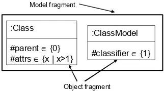
3.4.2. Model and object fragments for test adequacy criteria . . . 61
3.4.3. Discussion . . . 64
3.4.4. Automatic synthesis of test models . . . 65
3.5. Conclusion . . . 67
3.6. Acknowledgements . . . 68
3.7. Bibliography . . . 68
Chapter 4. Symbolic Execution-Based Techniques for Conformance Testing . . . 73
Christophe GASTON, Pascale LE GALL, Nicolas RAPIN and Assia TOUIL 4.1. Context . . . 73
4.1.1. Conformance testing: an introduction . . . 73
4.1.2. Conformance relation . . . 74
4.2. Input output symbolic transition systems . . . 79
4.2.1. Data types . . . 79
4.2.2. Input/output symbolic transition systems . . . 80
4.2.3. Semantics . . . 82
4.3. Symbolic execution . . . 84
4.4. Conformance testing for IOSTS . . . 87
4.4.1. Test purposes . . . 88
4.4.2. Preliminary definitions and informal description . . . 89
4.4.3. Inference rules . . . 94
4.5. Concluding remarks . . . 96
4.5.1. Choosing test purposes . . . 96
4.5.2. Implementation issues . . . 101
4.6. Bibliography . . . 101
Chapter 5. Using MARTE and SysML for Modeling Real-Time Embedded Systems . . . 105
Huascar ESPINOZA, Daniela CANCILA, Sébastien GÉRARD and Bran SELIC 5.1. Introduction . . . 105
5.2. Background . . . 108
5.2.1. UML profiling capabilities . . . 108
5.2.2. SysML and MARTE modeling capabilities . . 111
5.3. Scenarios of combined usage . . . 113
5.3.1. Defining architecture frameworks . . . 114
5.3.2. Requirements engineering . . . 115
5.3.3. System-level design integration . . . 117
5.3.4. Engineering/quantitative analysis . . . 120
5.4. Combination Strategies . . . 125
5.4.1. Issues . . . 125
5.4.2. Strategies . . . 128
5.5. Related work. . . 130
5.6. Conclusion . . . 133
5.7. Acknowledgements . . . 134
Chapter 6. Software Model-based Performance
Analysis . . . 139
Dorina C. PETRIU 6.1. Introduction . . . 139
6.2. Performance models . . . 142
6.2.1. Queuing network models . . . 144
6.2.2. Layered queuing network model . . . 146
6.3. Software model with performance annotations . . 148
6.3.1. Performance domain model . . . 148
6.3.2. Source model example . . . 152
6.4. Mapping from software to performance model . . 155
6.5. Using a pivot language: Core Scenario Model (CSM) . . . 158
6.6. Case study performance model . . . 160
6.7. Conclusions . . . 162
6.8. Acknowledgements . . . 163
6.9. Bibliography . . . 163
Chapter 7. Model Integration for Formal Qualification of Timing-Aware Software Data Acquisition Components . . . 167
Jean-Philippe BABAU, Philippe DHAUSSY and Pierre-Yves PILLAIN 7.1. Introduction . . . 167
7.2. System modeling . . . 170
7.2.1. Acquisition system modeling . . . 170
7.2.2. Case study . . . 172
7.2.3. Formal modeling techniques . . . 174
7.3. Variation points modeling . . . 182
7.3.1. Variation points definition . . . 184
7.3.2. CDL implementation . . . 187
7.4. Experiments and results . . . 189
7.4.1. Tools . . . 189
7.5. Conclusion . . . 194
7.6. Bibliography . . . 195
Chapter 8. SoC/SoPC Development using MDD and MARTE Profile . . . 201
Denis AULAGNIER, Ali KOUDRI, Stéphane LECOMTE, Philippe SOULARD, Joël CHAMPEAU, Jorgiano VIDAL, Gilles PERROUIN and Pierre LERAY 8.1. Introduction . . . 201
8.7.1. The platform independent model/application model in EML . . . 217
8.7.2. The platform model in EML . . . 217
8.7.3. The platform specific model/allocation model in EML . . . 218
8.9.1. Process validation through metamodeling with Kermeta . . . 223
8.9.2. Model transformation and generation with MDWorkbench platform . . . 224
8.10. HDL Code Generation . . . 225
8.10.1. VHDL code generation . . . 226
8.10.2. Rhapsody integration . . . 227
8.12. Acknowledgements . . . 229
8.13. Bibliography . . . 229
List of Authors . . . 233
Chapter 1
Model-driven engineering (MDE) is an approach to software development where the primary focus is on models, as opposed to source code. The use of models opens up new possibilities for creating, analyzing, manipulating and formally reasoning about systems at a high level of abstraction.
To reap all the benefits of MDE, it is essential to install a model transformation mechanism, that enables a wide range of different automated activities such as translation of models (expressed in different modeling languages), generating code from models, model synthesis, model improvement, model verification and model simulation. To achieve this, languages, formalisms, techniques, processes, tools and standards that support model transformation are needed. This chapter surveys the state of the art of model transformation, and discusses how it can be used to support some essential activities in MDE.
Chapter 2
UML formalism can be used to specify and build embedded software systems. It will deal specifically with:
− the Model-Driven Architecture principle of partitioning a system into domains for which we construct Platform Independent Models (PIMs);
− the use of Executable UML (xUML) for the construction of precise, complete PIMs that can be demonstrated and verified prior to implementation;
− automatic translation of the PIMs into Platform Specific Models (PSMs) and then into performance compliant code running on an embedded target.
Chapter 3
Model transformations can automate critical tasks in model-driven development. Thorough validation techniques are required to ensure their correctness. In this chapter we focus on testing model transformations. In particular, we present an approach for the systematic selection of input test data. This approach is based on a key characteristic of model transformations: their input domain is formally captured in a metamodel. A major challenge for test generation is that metamodels usually model an infinite set of possible input models for the transformation.
coverage criteria and for the automatic generation of test data. They also serve to drive the automatic generation of models for testing.
Chapter 4
In this chapter we discuss techniques to test whether a system conforms to its model given in terms of an Input/Output Symbolic Transition System (IOSTS). IOSTSs are automata-based models using data types to enrich transitions with data-based messages and guards depending on state variables. We focus on symbolic execution techniques both to extract IOSTS behaviors to be tested in the role of test purposes and to ground test case generation.
Chapter 5
Using model-based approaches for designing embedded systems helps remove unnecessary details in a manner that reduces production costs, increases the potential for easy validation and verification, and facilitates reuse and evolution. In this context, a common practice is to use UML as the base language, possibly specialized by the so-called profiles. Despite the ever increasing number of profiles being built in many domains, there is still insufficient focus on discussing the issue of combining multiple profiles. Indeed, a single profile may not be adequate to cover all aspects required in the multidisciplinary domain of embedded systems.
conclude, however, that a convergence agenda is highly desirable to ensure proper alignment of some key language features.
Chapter 6
This chapter starts with a brief review of performance modeling formalisms and a discussion of the performance annotations that need to be added to UML software models in order to enable performance analysis. The principles for transforming annotated software models into performance models are then presented. Such model transformations must bridge a large semantic gap between the source and the target model; hence a pivot model is often used. An example of such a transformation is given, from UML extended with the MARTE profile to the Layered Queueing Network performance model. The role of an intermediate pivot language called Core Scenario Model is also discussed. The chapter ends with a discussion of the lessons learned and future challenges for integrating the analysis of multiple non-functional properties in the context of MDE.
Chapter 7
performances, in terms of delays, for a certain context use. The approach is applied to sensor monitoring applications.
Chapter 8
Model Transformation:
A Survey of the State of the Art
Rien ne se perd, rien ne se crée, tout se transforme.
(Nothing is lost, nothing is created, everything is transformed)
Antoine-Laurent de Lavoisier (1743-1794)
1.1. Model-driven engineering
Model-Driven Engineering (MDE) is an approach to software development where the principle artefacts are models (as opposed to source code). It is a natural next step in the evolution of software development to continue to raise the level of abstraction in order to tackle increasingly complex problems. The main goal is to reduce the accidental complexity [BRO 86] of software, caused by the technology, methods and programming languages used to develop software. Of course, the essential complexity that is inherent to the problem to be solved cannot be reduced, no matter which approach, technology or language is adopted.
The basic principle behind MDE is that everything is a model. As such, it provides a generic approach to deal with all possible software artefacts used and produced during the software development life-cycle (e.g. requirement specifications, analysis and design documents, test suites, source code, and so on). Even the languages used to specify the models can be considered as models too, which are referred to as metamodels.
The current state-of-the-practiceof tool support for MDE is still in the round-trip engineering stage: the models and the code co-exist, and a change to either of the two artefacts requires a synchronization of the other. Ideally, this synchronization is automated, but in practice there is often some manual effort involved as well. In contrast, the state of the art in MDE support is model centric, where the code can be fully generated from the models [RAI 04].
Accepting the basic idea that everything is a model, and adopting a model-centric view, we need techniques and tools that allow us to manipulate and reason about such models. The technique that can be used to achieve this is commonly referred to as model transformation. According to [SEN 03, GER 02], model transformation is the heart and soul of model-driven software development. It is needed for supporting a wide range of model-driven activities such as code generation, model extraction, model refactoring, model verification, model simulation, and many more.
1.2. Model transformation
1.2.1.Definitions
definition is a set of transformation rules that together describe how a model in the source language can be transformed into a model in the target language. A transformation rule is a description of how one or more constructs in the source language can be transformed into one or more constructs in the target language.
This definition is very general, and covers a wide range of activities for which model transformation can be used: automatic code generation, model synthesis, model evolution, model simulation, model execution, model quality improvement (e.g. through model refactoring), model translation, model-based testing, model checking, model verification, and many more. For some types of activities we would like to support, the definition needs to be extended, in order to allow for model transformations that take more than one source model as input and/or produce multiple target models as output. The different source (resp. target) models do not even need to be described in the same modeling language. Examples of activities where we need more than one source or target model are model merging (in the context of collaborative modeling), model weaving and model composition [FLE 07, HID 09].
Schlaer-Mellor method [RAI 04]. To facilitate communication and interoperability, standards are needed for all of the above. The most obvious standards are those proposed by the OMG (e.g. UML, XMI, QVT, MOF, OCL, SysML and many more). Other de facto “standards” are those proposed by the Eclipse community (e.g. EMF, ECore, and so on).
1.2.2.Taxonomy
[MEN 06c] proposed a taxonomy of model transformation. Many of the ideas in this taxonomy were based on the discussions of a working group of a 2004 Dagstuhl seminar on Language Engineering for Model-Driven Software Development. We briefly review the essential parts of this taxonomy here.
Endogenous versus exogenous transformations
In order to transform models, these models need to be expressed in some modeling language (e.g. UML). A distinction can be made between endogenous and exogenous transformations, depending on the language(s) used to express source and target models involved in the model transformation. Endogenous transformations are transformations between models expressed in the same language. Exogenous transformations are transformations between models expressed using different languages.
A typical example of endogenous transformation is optimization: it aims to improve certain operational qualities (e.g. performance), while preserving the semantics of the model. A related endogenous transformation is model refactoring, which aims to improve the model structure.
Horizontal versus vertical transformations
An orthogonal way to classify model transformation is by looking at the abstraction level of its source and target models. For horizontal transformations, the source and target models must reside at the same level of abstraction. Typical examples are model refactoring (an endogenous transformation) and model translation (an exogenous transformation). For vertical transformations, the source and target models must reside at different abstraction levels. A typical example is refinement, where a specification is gradually refined into a full-fledged implementation, by means of successive refinement steps that add more concrete details [BAC 98].
1.3. Model transformation languages
Due to this wealth of transformation languages, it is necessary to provide a taxonomy that allows us to assess the conceptual commonalities and differences between these languages. This is the purpose of the current section.
Declarative versus operational
A first criterion to compare transformation languages is whether they rely on a declarative or an operational (a.k.a. imperativeor constructive) specification.
Declarative approaches focus on what needs to be transformed into what by defining a relationship or mapping between the source and target models. These approaches are attractive because they tend to be easier to write and understand by software engineers. In addition, desirable services such as source model traversal, traceability management and bidirectional transformations may be offered by the underlying transformation engine.
Operational approaches focus on how the transformation needs to be performed by specifying the steps that are required to derive the target models from the source models. Such approaches may be required to implement transformations for which declarative approaches fail to guarantee their services. Especially when the application order of a set of transformations needs to be controlled explicitly, an imperative approach is more appropriate thanks to its built-in notions of sequence, selection and iteration. Such explicit control may be required to implement transformations that reconcile source and target models after they have been both heavily manipulated outside the transformation tool.
example of the use of QVT Relational, while Figure 1.2 shows an example expressed in QVT Operational.
Figure 1.1.Part of the Class2RDBMS model transformation expressed using QVT Relational
transformation UML2RDBMS (in uml:UML, out rdbms:RDBMS) { // content of the transformation definition }
mapping Class:class2table() : Table when {self.isPersistent()}
{ name := 't_' + self.name;
column := self.attribute->map attr2column(); key := self.map class2key(result.column); }
mapping Attribute:attr2column() : Column { name := self.name;
type := getSqlType(self.type); }
mapping Class:class2key(in cols:Sequence(Column)) : Key { name := 'k_' + self.name;
column := cols[kind='primary']; }
Figure 1.2.Part of the Class2RDBMS model transformation expressed using QVT Operational
Textual versus visual
require us to specify the model transformations using a textual description. Visual transformation languages (such as nearly all of the graph transformation languages) specify model transformations in a visual way.
Note that some transformation languages offer both alternatives. For example, for QVT Relational[OBJ 08], both a visual and a textual syntax is available. The visual syntax is illustrated in Figure 1.1, whereas the textual syntax is illustrated in Figure 1.2.
Other distinguishing characteristics
Many other criteria can be used to compare or distinguish model transformation languages. For example, we can distinguish between general-purpose and domain-specific transformation languages. We can also distinguish between languages that have been designed and implemented in an ad hoc way as opposed to languages that have a formal underlying foundation. As we will see later, the latter type of languages can be exploited to achieve some kind of formal analysis of the model transformations they represent.
Finally, the expressivenessof the transformation language is also very important. Ideally, the language should provide mechanisms to facilitate (de)composition and reuse of model transformations, the ability to specify higher-order transformations (transformations that can transform transformations), the ability to specify bidirectional transformations (a possibility that is offered by triple graph grammar approaches [GIE 06] such as MOFLON1, and so
on).
1.4. Model transformation activities
In this section, we will provide a brief overview, with references to relevant literature, of a wide variety of
based activities in which model transformations are essential. While this overview is inevitably incomplete, it allows us to illustrate the importance and breadth of the field of model transformation.
Automatic code generation
Undoubtedly, code generation is one of the main motivations for using model transformation technology. It is used by various companies, including Airbus [SAB 09]. According to OMG’s MDA approach [KLE 03], the goal is to transform platform-independent models (PIMs) into platform-specific models (PSMs) and ultimately to source code generated from these models. According to our transformation taxonomy in section 1.2.2, code generation is an example of a vertical, exogenous transformation.
Ideally, this type of transformation should be as automated as possible. Seen in this light, a promising approach is Executable UML [RAI 04]. It uses an action semantics language integrated into a well-defined subset of the UML to allow full code generation from models.
Model extraction
Model extraction is another example of a vertical,
exogenous transformation. It is the inverse of code generation, and is an essential activity in reverse engineering and program comprehension. Taking the source code as input, it allows us to build a mental or visual model (e.g. a UML model) at a higher level of abstraction, in order to facilitate understanding of the code and how it is structured [MUR 01].
Model translation
modeling language, into an “equivalent” model in another modeling language. A typical example of such a model transformation, that has been used frequently in research literature is the Class2RDBMS model transformation (see, e.g. [WIM 07, HID 09]). Its aim is to convert a class model (e.g. a UML class diagram) into a relational database model. This transformation is sometimes referred to as the object-relational mapping. It provides a bridge between the world of object-oriented specifications and relational database specifications. A partial example of this transformation, expressed using QVT, has been presented in Figures 1.1 and 1.2.
Another important application of model translation is to cope with the ill-defined, underspecified, semantics of some modeling languages (such as UML) by translating them into another semantic domain that has a sound formal semantics, so that we can apply some form of formal analysis to our models. [ANA 07] attempted to transform UML models into the formal language Alloy, and encountered several problems in doing so. [VAN 03] proposed a translation of UML models into the description logics formalism. [HER 08] translated UML class and sequence diagrams into the domain of graph transformation, thereby giving an operational and denotational semantics to a subset of UML.
Model simulation and execution
If we have a model that represents a certain behavior, we can use model simulation to actually “run” the model in order to validate if it behaves in the way we would expect it to. The strongest form of model simulation is probably model execution, in which we transform the model into a runnable system, either using interpreter or compiler technology. Executable UML is an approach that supports this [RAI 04].
Model simulation may sometimes require manual intervention, in order to provide essential information to the simulator that cannot be derived from the model itself. Model simulation may be very useful to execute multiple alternative execution paths, in order to explore various “what-if” scenarios, so that the most appropriate one can be chosen once we decide to implement the model.
In the context of UML, useful examples are the simulation of behavioral diagrams, such as activity diagrams and state machine diagrams. In some cases, to achieve such simulation, an intermediate model translation step may be required to transform the model into a domain with which we can associate an operational semantics. For example, we can simulate the behavior of a UML activity diagram by first translating it into a Petri net, and then executing this Petri net [STÖ 05]. An alternative would be to translate it into a graph transformation system and execute that system [ENG 08, ERM 05].
Model checking, verification and validation
verifies whether the model is well-formed, i.e. whether it conforms to its metamodel and other constraints imposed by the modeling language. Semantic analysis can be done to verify dynamic or behavioral properties of the model, provided that the model is expressed in some formal semantic domain (possibly after having performed a model translation first).
A wide variety of model checking languages and tools exist (e.g. [CAB 07, VAR 04]), and the type of analysis we can do depends on the expressive power and properties supported by the associated formalism. For example, from a Petri net specification we can analyze properties such as reachability or deadlock freeness [PET 81]. From a graph grammar specification, we can analyze properties such as termination and confluence [HEC 02].
Next to model checking it is also necessary to validate and verify the model transformations themselves. Validation of model transformation allows us to assess whether the transformation is useful and meaningful. This can be achieved, for example, through model transformation testing and verification [NAR 08, BAU 09]. Verification of sets of model transformations is needed to ensure that they produce well-formed and correct models, and preserve (or improve) desirable properties such as (syntactical or semantical) correctness, consistency, and so on.
Model migration and co-evolution
Model transformations are also essential to cope with the inevitable evolution of models. In this context, an additional problem arises: not only do the models evolve, but so do the modeling languages in which these models are expressed [FAV 05]. With any change in the modeling language (e.g. a new version of UML that is introduced), model designers are confronted with the need to upgrade their models to this new version, or run the risk that their models will become obsolete or inconsistent. The activity of keeping models in sync with their evolving modeling languages is called model
co-evolution or co-adaptation, and has been investigated by various authors [WAC 07, HER 09].
Note that the problem of model co-evolution is much larger than what is explained above. In fact, any software artefact that is directly or indirectly related to a model may need to co-evolve. A typical example of this is the round-trip engineering process, in which models and source code co-exist, and need to be synchronized whenever a change is made to the model or the source code [D’H 00].
Model quality improvement
MEN 06a] so it is only a matter of time before UML modeling environments start supporting this activity.
Model inconsistency management
As a final example, the activity of model inconsistency managementis also well-suited to being supported by model transformation. Due to the fact that models are typically expressed using multiple viewpoints [GRU 98], are under constant evolution, and are often developed in a collaborative setting, inconsistencies in models cannot be avoided. Therefore, we need techniques based on model transformation to repair such inconsistencies. [MEN 06b] propose to do this using graph transformation, while [VAN 03] propose an approach based on description logics. Other formalisms may be suited to support this activity as well.
1.5. Conclusion
To conclude this chapter, I hope to have convinced the reader of the omnipresence of model transformation in all areas and activities of model-driven engineering. Given its importance, it is not surprising that there are so many different types of model transformation languages and tools around. Every approach has its own specific merits and shortcomings, so it is quite important to choose the most appropriate approach for a given purpose. Hopefully, this chapter will help you to make an informed choice, or incite you to carry out research in this exciting area of model-driven engineering.
1.6. Acknowledgements
This Chapter was written in the context of the research project “Model-Driven Software Evolution”, an Action de Recherche Concertée financed by the Ministère de la
l’Enseignement non obligatoire et de la Recherche scientifique, Belgium.
1.7. Bibliography
[ALE 04] ALEXANDRE CORREA C. W., “Applying Refactoring Techniques to UML/OCL Models”, Proc. Int’l Conf. Unified Modeling Language, vol. 3273 of Lecture Notes in Computer Science, Springer, October 2004, p. 173–187.
[ANA 07] ANASTASAKIS K., BORDBAR B., GEORG G., RAY I., “UML2Alloy: A Challenging Model Transformation”, Proc. Int’l Conf. Model Driven Languages and Systems, vol. 4735 of Lecture Notes in Computer Science, Springer, 2007, p. 436-450.
[BAC 98] BACK R.-J., VON WRIGHT J., Refinement Calculus, Springer, 1998.
[BAU 09] BAUDRY B., GHOSH S.,FRANCE R.,LE TRAON Y.,MOTTU
J.-M., “Barriers to Systematic Model Transformation Testing”,
Communications of the ACM, 2009, ACM.
[BRO 86] BROOKS F. P., “No Silver Bullet—Essence and accidents of software engineering”, Information Processing, vol. 86, 1986, p. 1069-1076, Elsevier Science.
[CAB 07] CABOT J.,CLARISÓ R., RIERA D., “UMLtoCSP: A tool for the formal verification of UML/OCL models using constraint programming”, Proc. Int’l Conf. Automated Software Engineering, 2007, p. 547–548.
[D’H 00] D’HONDT T., DE VOLDER K., MENS K., WUYTS R., “Co-Evolution of Object-Oriented Design and Implementation”,
Proc. Int’l Symp. Software Architectures and Component Technology: The State of the Art in Research and Practice, Kluwer Academic Publishers, January 2000.
[ERM 05] ERMEL C., HÖLSCHER K., KUSKE S., ZIEMANN P.,
“Animated simulation of integrated UML behavioral models based on graph transformation”, Proc. Symp. Visual Languages and Human-Centric Computing, IEEE Computer Society, 2005, p. 125–133.
[FAV 05] FAVRE J.-M., “Languages evolve too! Changing the
Software Time Scale”, Proc. Int’l Workshop on Principles of Software Evolution, IEEE Computer Society, 2005, p. 33-44.
[FLE 07] FLEUREY F., BAUDRY B., FRANCE R. B., GHOSH S., “A
Generic Approach for Automatic Model Composition”, GIESE H.,
Ed., MoDELS Workshops, vol. 5002 of Lecture Notes in Computer Science, Springer, 2007, p. 7-15.
[FOW 99] FOWLER M., Refactoring: Improving the Design of Existing Code, Addison-Wesley, 1999.
[GER 02] GERBER A.,LAWLER M.,RAYMOND K.,STEEL J.,WOOD A.,
“Transformation: The Missing Link of MDA”, Proc. Int’l Conf. Graph Transformation, vol. 2505 of Lecture Notes in Computer Science, Springer, 2002, p. 90–105.
[GIE 06] GIESE H., WAGNER R., “Incremental Model
Synchronization with Triple Graph Grammars”, Proc. Int’l Conf. Model Driven Engineering Languages and Systems, vol. 4199 of Lecture Notes in Computer Science, Springer, 2006, p. 543–557.
[GRU 98] GRUNDY J. C., HOSKING J. G., MUGRIDGE W. B.,
“Inconsistency Management for Multiple-View Software Development Environments”, IEEE Trans. Software Engineering, vol. 24, num. 11, 1998, p. 960-981.
[HEC 02] HECKEL R.,MALTE KÜSTER J.,TAENTZER G., “Confluence
of Typed Attributed Graph Transformation Systems”, Proc. Int’l Conf. Graph Transformation, vol. 2505 of Lecture Notes in Computer Science, Springer, 2002, p. 161–176.
[HER 08] HERMANN F., EHRIG H., TAENTZER G., “A Typed
[HER 09] HERRMANNSDOERFER M.,BENZ S.,JUERGENS E., “COPE:
Automating Coupled Evolution of Metamodels and Models”,
Proc. European Conference on Object-Oriented Programming, Lecture Notes in Computer Science, Springer, 2009.
[HID 09] HIDAKA S., HU Z., KATO H., NAKANO K., “Towards a
compositional approach to model transformation for software development”, SAC ’09: Proceedings of the 2009 ACM Symposium on Applied Computing, New York, NY, USA, 2009, ACM, p. 468–475.
[KLE 03] KLEPPE A., WARMER J., BAST W., MDA Explained, The Model-Driven Architecture: Practice and Promise, Addison Wesley, 2003.
[KRU 03] KRUCHTEN P., The Rational Unified Process: An Introduction, Addison-Wesley, 3rd edition, 2003.
[KÜS 06] KÜSTER J. M., “Definition and validation of model
transformations”, Software and System Modeling, vol. 5, num. 3, 2006, p. 233-259.
[MAR 05] MARKOVIC S., BAAR T., “Refactoring OCL Annotated
UML Class Diagrams”, Proc. Int’l Conf. Model Driven Engineering Languages and Systems, vol. 3713 of Lecture Notes in Computer Science, Springer, 2005, p. 280–294.
[MEN 06a] MENS T., “On the Use of Graph Transformations for
Model Refactoring”, Generative and Transformational Techniques in Software Engineering, vol. 4143 of Lecture Notes in Computer Science, Springer, 2006, p. 219-257.
[MEN 06b] MENS T., VAN DER STRAETEN R., D’HONDT M.,
“Detecting and Resolving Model Inconsistencies Using Transformation Dependency Analysis”, Proc. Int’l Conf. Model Driven Engineering Languages and Systems, vol. 4199 of Lecture Notes in Computer Science, Springer, October 2006, p. 200-214.
[MEN 06c] MENS T., VAN GORP P., “A Taxonomy of Model
[MUR 01] MURPHY G. C., NOTKIN D., SULLIVAN K. J., “Software
Reflexion Models: Bridging the Gap between Design and Implementation”, IEEE Transactions on Software Engineering, vol. 27, num. 4, 2001, p. 364-380, IEEE Computer Society.
[NAR 08] NARAYANAN A., KARSAI G., “Towards Verifying Model
Transformations”, Notes in Theoretical Computer Science, num. 211, 2008, p. 191–200, Elsevier.
[OBJ 07] OBJECT MANAGEMENT GROUP, “XML Metadata Interchange (XMI) version 2.1.1”, formal/2007-12-01, December 2007.
[OBJ 08] OBJECT MANAGEMENT GROUP, “Query/View/ Transformation Specification version 1.0”, formal/2008-04-03, April 2008.
[PET 81] PETERSON J. L., Petri Net Theory and the Modeling of Systems, Prentice Hall, 1981.
[POR 03] PORRES I., “Model Refactorings as Rule-Based Update
Transformations”, STEVENS P., WHITTLE J., BOOCH G., Eds., UML 2003 - The Unified Modeling Language, vol. 2863 of Lecture Notes in Computer Science, Springer, 2003, p. 159-174.
[RAI 04] RAISTRICK C.,FRANCIS P.,WRIGHT J.,CARTER C.,WILKIE
I., Model Driven Architecture with Executable UML, Cambridge, 2004.
[SAB 09] SABATIER L.,POUPART E.,DALBIN J.-C.,BAZEX P.,LE THI
T.-T., MILLIAN T., “Transformation de modèles pour des
applications aéronautiques et spatiales: vérification de propriétés”, Journées NEPTUNE’2009, 2009.
[SEN 03] SENDALL S., KOZACZYNSKI W., “Model Transformation:
The Heart and Soul of Model-Driven Software Development”,
IEEE Software, vol. 20, num. 5, 2003, p. 42–45, Special Issue on Model-Driven Software Development.
[STE 04] STEEL J., LAWLEY M., “Model-Based Test Driven
Development of the Tefkat Model-Transformation Engine”,
[STÖ 05] STÖRRLE H., HAUSMANN J. H., “Towards a Formal
Semantics of UML 2.0 Activities”, LIGGESMEYER P., POHL K.,
GOEDICKE M., Eds., Software Engineering, vol. 64 of LNI, GI,
2005, p. 117-128.
[VAN 03] VAN DER STRAETEN R.,MENS T.,SIMMONDS J.,JONCKERS
V., “Using Description Logics to Maintain Consistency Between UML Models”, Proc. Unified Modeling Language, vol. 2863 of Lecture Notes in Computer Science, Springer, 2003, p. 326–340.
[VAN 05] VAN KEMPEN M.,CHAUDRON M.,KOUDRIE D.,BOAKE A.,
“Towards Proving Preservation of Behaviour of Refactoring of UML Models”, Proc. SAICSIT 2005, 2005, p. 111-118.
[VAR 04] VARRÒ D., “Automated formal verification of visual
modeling languages by model checking”, Software and Systems Modeling, vol. 3, num. 2, 2004, p. 85-113, Elsevier.
[WAC 07] WACHSMUTH G., “Metamodel Adaptation and Model
Co-adaptation”, Proc. European Conf. Object-Oriented Programming, vol. 4609 of Lecture Notes in Computer Science, Springer, 2007, p. 600–624.
[WIM 07] WIMMER M., STROMMER M., KARGL H., KRAMLER G.,
“Towards Model Transformation Generation by Example”, Proc. 40th Hawaii Int’l Conf. System Sciences, IEEE Computer Society, 2007.
[ZHA 05] ZHANG J.,LIN Y.,GRAY J., “Generic and Domain-Specific
Model Refactoring using a Model Transformation Engine”,
Model-Based Code Generation
2.1. Introduction
The benefits of an implementation-free model, fashionably named Platform Independent Model (PIM), are now widely recognized. However, the space and speed constraints characteristic of many embedded systems means there is necessarily a significant distortion of the PIM when deriving a Platform-Specific Implementation (PSI). This leads to the situation where maintenance of the PIM in the face of changes to the PSI becomes very costly, and in many cases is abandoned, leaving the PIM to fall into obsolescence. It is then the PSI that must be maintained in the face of requirement changes. The problem with the PSI is that it is many times larger and more complex than the PIM, and is correspondingly more expensive to maintain. Also, it is obviously platform-specific, so migration to a new platform, where different optimizations may be required, becomes increasingly difficult.
What we need is a process that allows us to maintain a clear separation between the specification of required behavior, and the specification of how that behavior should be realized in an optimized way on a specific platform. This paper describes such a process.
2.2. The model-driven architecture (MDA) process
MDA defines two primary types of model: the Platform Independent Model (PIM) and the Platform Specific Model (PSM). Here the term platform is used to refer to technology and engineering details that are irrelevant to the fundamental functionality of the software.
These model types are a key concept in MDA; it mandates the separation of concerns of analysis (the PIM) from its realization on a particular computing platform and technology (the PSM) and recognizes that the refinement relationship between the two types of model should be achieved by applying a mapping. It goes on to state that such a mapping may be used to realize many such refinement relationships between different PIMs and their corresponding PSMs (i.e. they can be reused); furthermore, it states that the mapping can be captured as a model itself, expressed in UML. It also recognizes that the PIM to PSM mapping may be fully automated if we define both the PIM and the mapping with sufficient rigor.
2.3. The automated approach to code generation
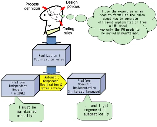
MDA encourages the designers to formalize the rules about how to transform models into code. This means that all components are generated in a consistent and comprehensible way. We shall say more about how the translation rules are formalized later.
Figure 2.1.
The automated approach has the advantage that only the PIM needs to be maintained, avoiding the tendency for specification and implementation to become out of step.
Let us consider the automated approach in more detail.
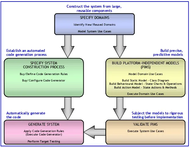
Figure 2.2 outlines the process of MDA with xUML, in which:
smaller and simpler, and consequently less expensive to construct and test. Use of Executable UML (xUML) to express the models means that they can be verified in a simulation environment prior to implementation;
− the verified PIMs are automatically transformed into a Platform-Specific Implementation in the desired target language.
With this strategy, all the business intellectual property is captured, in reusable form, as xUML models. Because application knowledge is held in PIMs, its longevity is guaranteed, as it will not become obsolete when today’s technologies are superseded.
Establish an automated code generation process
Build precise, predictive models
Subject the models to rigorous testing before implementation Construct the system from large,
reusable components Build Static Model - C lass Diagram Build Behavioural Model - State Charts & Operations
Build Action Model - State Actions & Methods Exec ute Domain Use Cases SPECIFY SYSTEM
Subject the models to rigorous testing before implementation Construct the system from large,
reusable components Build Static Model - C lass Diagram Build Behavioural Model - State Charts & Operations
Build Action Model - State Actions & Methods Exec ute Domain Use Cases SPECIFY SYSTEM
Figure 2.2. The MDA process and work products
mature engineering disciplines, such as electronic engineering, aeronautical engineering and civil engineering. These engineering disciplines are characterized by the way that engineers routinely:
− construct the product from large reusable components;
− build precise, predictive models;
− subject the models to rigorous testing prior to implementation;
− establish a well-defined, highly automated construction process.
The following sections describe the process and its artifacts in more detail.
2.4. Domain modeling
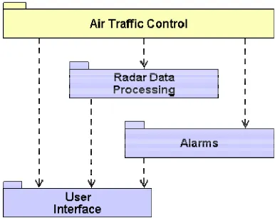
Domain-based or subject matter-based partitioning is today a widely accepted and mature partitioning strategy. The basis for domain partitioning is to recognize that any system comprises a set of subject matters, or domains. These units will be used as a basis for partitioning the analysis effort for the system. A domain will comprise a number of classes and can be represented in UML using a package.
Figure 2.3. A simplified domain chart for an air traffic control system
A domain is defined as “a separate real, hypothetical or abstract world inhabited by a distinct set of classes that behave according to the rules and policies characteristic of that domain”.
Sounds intimidating? We can unpack the definition into smaller components:
“A separate real, hypothetical or abstract world” means that the domain might represent a “real world”, such as Air Traffic Control, Military Command and Control or Patient Administration for instance. Such a domain usually reflects the end user requirements directly. We typically have little or no discretion over these domains; we just formalize the requirements that impinge upon them, aided by any use cases or other requirements that have been documented.
Interface or Alarms domain. In these domains, the requirements are invented by us to meet the overall needs of the system. For example, we need to establish a policy regarding unavailable menu items; are they grayed out or are they not shown?
“A distinct set of classes” means that a class should appear in only one domain. Note, though, that the same real world thing can appear at different levels of abstraction on different domains. For example, a real aircraft might appear as an Aircraft, Freight Carrying Vehicle, Serviceable Item, Radar Track and Icon in various domains. These are known as counterpart classes.
“Behave according to the rules and policies characteristic of the domain” means that each class understands the context within which it exists. An Aircraft class in the Air Traffic Control domain embodies air traffic control rules about separation and so forth. It knows nothing about how it is displayed and its behavior is only modeled from the viewpoint of its containing domain.
AIRCRAFT
AIRCRAFT
It is a policy of Air Traffic Control that I must remain at least 3 miles horizontally and 1000 feet vertically from all other aircraft.
Class in Air Traffic Control Domain (a “real”world)
Figure 2.4. A class from the air traffic control domain
domain partitioning; it leads to simpler classes that are easier to test and reuse.
ICON
ICON
It is a policy of this User Interface
that I must become opaque if I am in front of another icon
Class in User Interface Domain (an “abstract” world)
Figure 2.5. A class from the user interface domain
This approach exhibits a number of distinct advantages: − Reuse: each domain is largely self contained, forming a potentially large reusable component.
− Well defined interfaces: a domain presents a well-defined, contractual interface to other domains which may want to use its services.
− Effective utilization of subject matter knowledge: each domain is a subject matter in its own right, therefore subject matter experts may analyze the appropriate domain (or set of domains), unhindered by consideration of other knowledge areas unfamiliar to them.
− Stability to changing requirements: the domain that captures the purpose of the system, with regard to the end users point of view, is the application domain; it will typically be augmented as further requirements are modeled, whilst domains further down the domain chart are isolated from such changes.
incorporated into the framework of the system. Domain partitioning recognizes this issue and allows service domains (those that represent highly reusable, technology-oriented subject matters) to be replaced in a highly modular fashion, without affecting other domains.
− Incorporation of third party software: many systems will incorporate legacy code, third party libraries or services. Domain partitioning recognizes that this is a risk area for any project and defines such units as implementation domains. The domain approach therefore does not insist upon a homogeneous approach, but rather manages the interfaces between differing components, promoting the use of COTS (Commercial Off-The-Shelf) software where appropriate.
− Incorporation into a use case driven approach: interaction diagrams are used to document use cases in terms of the domain level interactions. A high-level view of system interactions is extremely valuable and can be used to help scope each domain and define its interfaces.
These are the principles that underpin the MDA process; we separate our system into subject matters, some application-oriented, some representing pervasive services such as communications and persistence, and some technology-oriented.
A PIM is built for each domain, with well-defined interfaces. Each PIM is uncontaminated by other subject matters makes it both simple and reusable.
2.5. The executable UML (xUML) formalism
various aspects of object-oriented systems. Let us examine the contrast between UML and xUML.
UML specifies a diagrammatic language that allows systems to be specified using a number of diagram types; however it is quite informal about how the different diagrams are to be used. For example, state machines can be used to describe use cases, subsystems and objects. This means that a reader must first establish the context for the diagram they are reading before being able to understand it.
In xUML, notations are used for a specific purpose: a state chart is always associated with a class, so a state machine always describes the behavior of an object.
In summary, xUML is a simple, precise subset of UML, specifically designed to allow construction of rigorous PIMs. The key facets of xUML are illustrated in Figure 2.6, which shows that:
− each system is partitioned into domains, representing areas of expertise;
− each domain is partitioned into classes, which together will fulfill the data and processing requirements of each domain;
− each class can have a state machine, which processes asynchronous signals directed to that class by executing state actions;
− each class can have operations, which perform synchronous processing.
Figure 2.6. xUML model layers
There are many benefits that accrue from use of a precise UML subset, including reduced learning costs and less idiosyncratic models, but those that impinge directly on system generation are:
−there are fewer translation rules to define, reducing the cost of building a code generator;
− the runtime overheads, especially those associated with state machines can be drastically reduced.
2.6. System generation
Figure 2.7. Modeling and code generation
A typical code generator suite consists of:
− Code Generator: a set of metamodels that form the basis for translating xUML models into code;
− xUML Runtime Layer: a portable run-time library. This provides the xUML “Virtual Machine” upon which the generated code will execute. In some embedded target architectures, the runtime is either very thin or non-existent, allowing generation of very compact implementations;
−Adaptation Layer: a non-portable, platform-dependent run-time library. This maps the run-time layer onto the underlying operating system and middleware. The interface to the Adaptation Layer is well-defined, allowing users to build their own, if an off-the-shelf implementation for any specific operating system is unavailable;
− xUML-Code Mappings: a set of language-specific
mappings, typically bought off-the-shelf, specifying the rules for translating xUML models into that language. These can be configured by users if required to achieve specific target code qualities. Alternatively, users can define their own complete set of xUML-Code mappings to meet their particular needs.
the models’ structure and parsing the action language. The yellow shaded components in Figure 2.7 are those typically configured by users to address specific requirements for their target system.
The code generator itself is a set of domain models expressed using xUML. The domains represent the various components of an xUML system, and the classes represent the elements that make up those components. Figure 2.8 below shows that the “Executable UML” domain (or formalism) contains the notions “Domain”, “Class” and “Attribute”. Each element contains operations which specify how to map that xUML element onto a specific target language. Different action language methods can be embedded within these models to generate code in different target languages with different static and runtime characteristics. For example, the class “Class” has an operation named “generateCode”, for which many rival methods can be specified to map a UML class to C, C++, Java, Ada or any other language as required.
(Part of) /* "[T:this.class_name]" Class Header */ struct s_object *next_instance; /* "[T:this.class_name]" Class Header */ struct s_object *next_instance;
2.7. Executable UML to code mappings
Although the general MDA process permits multiple transformations from PIM to PSM to PSI, we will look initially at the idea of transforming PIMs expressed in executable UML directly into a PSI (i.e. code). That is, we will look at the construction of an executable UML code generator. Given an xUML model, there are a large number of ways that we might generate code. Some issues are illustrated in Figure 2.9 below, which shows some candidate design decisions regarding target language, software organization paradigm, memory management strategy, scheduling strategy, distribution scheme, persistence mechanisms and so on.
Software Architecture
Figure 2.9. Software architecture decisions
For the purposes of code generation, we will refer to the particular choice of all these factors as the “Software Architecture” or simply “Architecture” for the system.
target code. Figure 2.10 below shows an example of the translation of a fragment of an xUML model into target code in a hypothetical architecture. For the remainder of this Chapter, we will refer to this example architecture as HA-1. HA-1 is a single task, ‘C’-based architecture. Note that this approach does not assume use of an object-oriented programming language, which in an embedded system can impose unwelcome overheads. In HA-1, the translation rules that have been developed require that objects of each class are held as a linked list of structures.
The structure members are derived both from the xUML model and from the fixed requirements of the architecture itself. In the lower box of the figure, we can see the translated structure definition for the “Target” class in the xUML model fragment. This structure has the following features:
− a unique name for the structure type derived from the number of the domain model (43) that the “Target” class resides in, and from the number of the “Target” class itself (3);
− various generic structure members (next_instance, prev_instance, rel_ptr and cpr_ptr) which are memory pointers for maintaining the linked list of objects as well as pointers to the intra-domain and inter-domain (counterpart) relationships that the object is currently participating in;
−one structure member for each attribute of the “Target” class in the xUML model, the type of each of which is derived from the type stored in the xUML model;
− to aid readability of the generated code, a comment has been placed in the structure definition indicating that it has been generated from the “Target” class.
Platform Independent Model : Class Diagram Platform Independent Model : Class Diagram
Generated C Code Generated C Code
Translate
Figure 2.10. Example PIM to code mapping
In a later version of HA-1 perhaps, we would wish to improve both the performance and size of the generated code. Some of the options that we might consider are:
− remove the “currentWeaponId” member of the D43_C3 (“Target”) structure, because this referential attribute is never read at run time;
− for classes with a “Static Population” tag attached to them, use a statically allocated array of structures to hold the instance data. This would require that for such tagged classes the “next_instance” and “prev_instance” members would not appear in the generated structure definition;
pointer to (in this case) the current and pending “Weapon” instances;
− combine pairs of classes with mandatory one-to-one relationships between them with a single structure definition incorporating the attributes of both classes. This would involve:
- changed generation of the structure definition,
- changed code generation from all the ASL that accessed instances and attributes of the classes concerned,
- changed code generation for any association manipulation,
- reconciliation with any class/instance dispersal strategies if HA-1 was to become distributed,
- management of the case where both combined classes have state models.
From this discussion we can see that a code generator may be called upon to perform very subtle and complex mappings from xUML models into code. The execution of such mappings might involve taking information from a wide variety of sources within the model and making complex decisions about the best route for generation. To clarify what is going on inside the translator as it executes; the steps involved in generating code from a PIM are described below.
Step 1: Build the PIM
The domain experts build PIMs using xUML, such as this one:
Platform Independent Model : Class Diagram
Step 2: Populate the metamodels
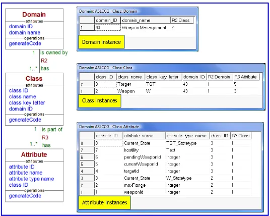
We first consider the “Executable UML” domain. As shown in Figure 2.12 below, this domain contains classes such as “Domain”, “Class” and “Attribute”. This figure also shows examples of the instances of these classes when the domain is populated with the example PIM (“Weapon − Target”) that was introduced in Figure 2.11 above.
We can see that our PIM has one domain, two classes and a total of eight attributes (including the two “Current_State” attributes as both classes have a state machine), and these manifest themselves as objects in the populated metamodel. We use a Populator that instantiates the metamodels with this information obtained from the PIM.
Domain Instance
Class Instances
Attribute Instances
Figure 2.12. Example populated executable UML metamodel
Step 3: Generate the code
Figure 2.13 below shows part of a translation engine, written in ASL, which generates the first part of the class headers for our hypothetical architecture HA-1.
Figure 2.13. Example class model code generation rules
The operation of this code generator is summarized below: − Generation of the code for the domain is initiated by calling operation “generateCode” on the solitary “Domain” object.
− The ASL in this “Class.generateCode” method (in the middle box in Figure 2.13) generates the first part of the structure definition for HA-1. This operation accesses attributes of the “Domain” and “Class” classes to generate the header code. The actual code construction is carried out by the $FORMAT block which is an ASL feature that allows modelers to perform string manipulation. The construct takes the literal text between the $FORMAT and $ENDFORMAT markers and outputs it to the entity called “header_file” which is a data item of type “File”. Within the literal text of the $FORMAT block there are embedded substitutions delineated by use of square brackets “[ .... ]”. These specify that the value of the variable whose name is shown in the brackets should be substituted into the text. The characters before the colon (“:”) are format specifications.
− Once the class-specific part of the header file has been generated, the method finds the set of all attributes for this class by navigating association R3 in the “Executable UML” domain. The ASL then iterates over all instances of “Attribute” in the set, and for each instance invokes the operation “generateCode” on the “Attribute” class.
−The ASL in the “Attribute.generateCode” method (in the bottom box in Figure 2.13) accesses the attributes “attribute_name” and “attribute_type_name” of the “Attribute” instance to format a structure member declaration. In HA-1 the mapping between ASL types and “c” types is achieved via a header file that contains fixed typedefs for all the ASL types.
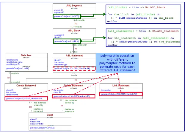
polymorphic operation with different polymorphic methods to
generate code for each different ASL statement polymorphic operation
with different polymorphic methods to
generate code for each different ASL statement
Figure 2.14. Example action language code generation rules
In this model, code generation for each “ASL Segment” (typically a state action or operation method) is initiated by invoking “generateCode” on the “ASL Segment” object. This in turn finds all linked “ASL Block” objects across R4 and invokes “generateCode” on each of these. These in turn find all linked “ASL Statement” objects across R5, and invoke “generateCode” on each of these. Note that the “generateCode” operation of the “ASL Statement” class is polymorphic, allowing us to implement rival versions of this method for each type of ASL statement, represented as the subclasses “Create Statement”, “Delete Statement” and so on.
2.8. Conclusions
approach. xUML is used to capture abstract platform models, and system generation is achieved by creating ASL that iterates over the information captured by these models.
Using this approach, developers can separate platform independent aspects of the system from specific platform details thus realizing the benefits of:
−reusable platform independent models;
−simpler, easier to understand, views of the system;
while avoiding the pitfalls of:
− the laborious creation of elaborated platform specific models;
− the triple redundancy involved in maintaining separate PIMs, PSMs and PSIs.
The strategy enables very sophisticated code generators to be realized, enabling developers to address the needs of the most demanding real-time embedded systems.
2.9. Bibliography
[RAI 04] RAISTRICK, C. et al., Model Driven Architecture with
Testing Model Transformations:
A Case for Test Generation from
Input Domain Models
3.1.
IntroductionModel transformation is a key mechanism when building distributed real-time systems (DRES) with model-driven development (MDD). It is used to automatically perform a large number of tasks in the development of DRES. The DOC group at Vanderbilt University has extensively investigated MDD for DRES. In this context, Madl et al. [MAD 06] use model transformations in order to apply model checking techniques on early design models, Gokhale et al. [GOK 08] develop model transformations that automate deployment tasks of component-based DRES and Shankaran et al. [SHA 09] use model transformations to dynamically adapt a DRES when its environment changes. The ACCORD/UML [GER 00] methodology developed by CEA also makes an extensive use of model transformations for a
model-driven development of DRES. Model transformations encapsulate specific steps in the development methodology and generate optimized code. Airbus develops large model transformations that automatically generate optimized embedded code for the A380 from SCADE models.
Due to the critical role that model transformations play in the development of DRES, thorough validation techniques are required to ensure their correctness. A fault in a transformation can introduce a fault in the transformed model, which, if undetected and not removed, can propagate to other models in successive development steps. As a fault propagates further, it becomes more difficult to detect and isolate. Since model transformations are meant to be reused, faults present in them may result in many faulty models. Several studies have investigated static verification techniques for model transformations. For example, Küster [KUS 06] focuses on the formal proof of the termination and confluence of graph transformation, and Anastasakis et al. [ANA 07] analyze properties on a formal specification of the transformation in alloy.
In this paper we are interested in adapting software testing techniques to validate model transformations. In particular, we focus on the generation and qualification of test data for model transformations. To test a model transformation, a tester will usually provide a set of test models, run the transformation with these models and check the correctness of the result.
Model transformations specify how elements from the source metamodel are transformed into elements of the target metamodel. The source metamodel completely specifies the input domain of the transformation: the set of licit input models. In this context, the idea is to evaluate the adequacy of test models with respect to their coverage of the source metamodel. For instance, test models should instantiate each class and each relation of the source metamodel at least once. In the following we present test adequacy criteria based on the coverage of the source metamodel. We also discuss the automatic generation of test models that satisfy these criteria.
Before presenting the specific generation of test data for model transformation, we recall general techniques and current challenges for test generation from a model of the input domain. We briefly introduce category-partition testing [OST 88] and combinatorial interaction testing [COH 97] as two black-box techniques for the systematic selection of a subset of values in large domains. These techniques are a specific case of model-based testing.
Utting et al. [UTT 07b] identify four different approaches to model-based testing: generation of test data from a domain model, generation of test cases from an environmental model, generation of test cases with oracle from a behavior model, generation of test scripts form abstract tests. Utting et al.’s book focuses mainly on the third approach, while in this Chapter we will introduce techniques related to the first approach. Ammann et al.
3.2. Challenges for testing systems with large input domains
One important aspect of the growing complexity of software systems is that these systems tend to be increasingly open to their environment. In particular, this means that many systems can operate on a very large amount of information provided by the user and/or offer mechanisms for dynamic reconfiguration. In both cases, these systems are characterized by a very large domain on which they have to run. It is usually not possible to test these systems with all possible input and in all possible configurations. The challenge for test data generation is to propose criteria to systematically select a subset of data that will still ensure a certain level of trust in the system being tested.
In this section we present several examples where such issues occur for test generation.
3.2.1. Large set of input data
The first category of systems that has a large input domain is the set of all programs that process a large set of data. These data can be provided by other software components or by users. Examples of these systems are all the web applications that process user input provided through a form.
IEEE contact. In addition to the large domains for each variable, the global input domain for this page is the total number of combinations of values for each variable. This number is 72 * 229 * 4 * 2 * 14#String values. It is important to
note that there exist some constraints between the fields that reduce the number of combinations. For example, if the country is neither Canada nor the USA, there is no need to provide a value for the Province/State field. In order to test this registration system, it is necessary to select a subset of all possible input values. In particular, it is necessary first to reduce the set of all possible String values to a finite set of test data; and second to select a small number of configurations of data.