PROGRAM ARDUINO
int rain_pin = A0;
int ldr_pin = A1;
int rain_sensor = 0;
int ldr_sensor = 0;
int In1 = 2;
int In2 = 3;
int pwmpin = 5;
int limit_keluar = 6;
int limit_masuk = 7;
int limit_out;
int limit_in;
void setup() {
// put your setup code here, to run once:
Serial.begin(9600);
pinMode(In1, OUTPUT);
pinMode(In2, OUTPUT);
pinMode(pwmpin, OUTPUT);
pinMode(limit_keluar, INPUT_PULLUP);
pinMode(limit_masuk, INPUT_PULLUP);
}
void loop() {
// put your main code here, to run repeatedly:
rain_sensor = analogRead(rain_pin);
ldr_sensor = analogRead(ldr_pin);
// Serial.print(rain_sensor);
// Serial.print(" , ");
// Serial.println(ldr_sensor);
if(rain_sensor<800 || ldr_sensor<200){
simpan();
}
else{
jemur();
}
// jemur();
// simpan();
}
{
do{
digitalWrite(In1, LOW);
digitalWrite(In2, HIGH);
analogWrite(pwmpin, 255);
limit_out = digitalRead(limit_keluar);
}
while(limit_out == HIGH);
digitalWrite(In1, LOW);
digitalWrite(In2, LOW);
analogWrite(pwmpin, 0);
Serial.println("jemur");
}
void simpan()
{
do{
digitalWrite(In1, HIGH);
digitalWrite(In2, LOW);
analogWrite(pwmpin, 255);
limit_in = digitalRead(limit_masuk);
}
Arduino Nano 3.0 (ATmega328):
schematic
,
Eagle files
.
Arduino Nano 2.3
(ATmega168): manual(pdf), Eagle files.
Note:
since the free version of
Eagle does not handle more than 2 layers, and this version of the Nano is 4 layers, it is
published here unrouted, so users can open and use it in the free version of Eagle.
Microcontroller Atmel ATmega168 or ATmega328
Operating Voltage (logic
level) 5 V
Input Voltage
(recommended) 7-12 V
Input Voltage (limits) 6-20 V
Digital I/O Pins 14 (of which 6 provide PWM output)
Analog Input Pins 8
DC Current per I/O Pin 40 mA
Flash Memory 16 KB (ATmega168) or 32 KB (ATmega328) of which 2 KB used by
bootloader
SRAM 1 KB (ATmega168) or 2 KB (ATmega328)
EEPROM 512 bytes (ATmega168) or 1 KB (ATmega328)
Clock Speed 16 MHz
The Arduino Nano can be powered via the Mini-B USB connection, 6-20V unregulated external power supply (pin 30), or 5V regulated external power supply (pin 27). The power source is automatically selected to the highest voltage source.
The FTDI FT232RL chip on the Nano is only powered if the board is being powered over USB. As a result, when running on external (non-USB) power, the 3.3V output (which is supplied by the FTDI chip) is not available and the RX and TX LEDs will flicker if digital pins 0 or 1 are high.
The ATmega168 has 16 KB of flash memory for storing code (of which 2 KB is used for the bootloader); the ATmega328 has 32 KB, (also with 2 KB used for the bootloader). The ATmega168 has 1 KB of SRAM and 512 bytes of EEPROM (which can be read and written with the EEPROM library); the ATmega328 has 2 KB of SRAM and 1 KB of EEPROM.
Each of the 14 digital pins on the Nano can be used as an input or output, using pinMode(), digitalWrite(), and digitalRead()functions. They operate at 5 volts. Each pin can provide or receive a maximum of 40 mA and has an internal pull-up resistor (disconnected by default) of 20-50 kOhms. In addition, some pins have specialized functions:
Serial: 0 (RX) and 1 (TX). Used to receive (RX) and transmit (TX) TTL serial data. These pins are connected to the corresponding pins of the FTDI USB-to-TTL Serialchip.
External Interrupts: 2 and 3. These pins can be configured to trigger an interrupt on a low value, a rising or falling edge, or a change in value. See theattachInterrupt()function fordetails.
PWM: 3, 5, 6, 9, 10, and 11. Provide 8-bit PWM output with theanalogWrite()function.
SPI: 10 (SS), 11 (MOSI), 12 (MISO), 13 (SCK). These pins support SPI communication, which, althoughprovidedbytheunderlyinghardware,isnotcurrentlyincludedintheArduinolanguage.
LED: 13. There is a built-in LED connected to digital pin 13. When the pin is HIGH value, the LED is on, when the pin is LOW, it'soff.
The Nano has 8 analog inputs, each of which provide 10 bits of resolution (i.e. 1024 different values). By default they measure from ground to 5 volts, though is it possible to change the upper end of their range using the analogReference()function. Additionally, some pins have specialized functionality:
I2C: 4 (SDA) and 5 (SCL). Support I2C (TWI) communication using theWire library(documentation on the Wiringwebsite).
There are a couple of other pins on the board:
AREF. Reference voltage for the analog inputs. Used withanalogReference().
Reset. Bring this line LOW to reset the microcontroller. Typically used to add a reset button to shields which block the one on theboard.
The Arduino Nano has a number of facilities for communicating with a computer, another Arduino, or other microcontrollers. The ATmega168 and ATmega328 provide UART TTL (5V) serial communication, which is available on digital pins 0 (RX) and 1 (TX). An FTDI FT232RL on the board channels this serial
communication over USB and the FTDI drivers(included with the Arduino software) provide a virtual com port to software on the computer. The Arduino software includes a serial monitor which allows simple textual data to be sent to and from the Arduino board. The RX and TX LEDs on the board will flash when data is being transmitted via the FTDI chip and USB connection to the computer (but not for serial communication on pins 0 and 1).
A SoftwareSerial libraryallows for serial communication on any of the Nano's digital pins.
The ATmega168 and ATmega328 also support I2C (TWI) and SPI communication. The Arduino software includes a Wire library to simplify use of the I2C bus; see the documentationfor details. To use the SPI communication, please see the ATmega168 or ATmega328 datasheet.
The Arduino Nano can be programmed with the Arduino software (download). Select "ArduinoDiecimila, Duemilanove, or Nano w/ ATmega168" or "ArduinoDuemilanove or Nano w/ ATmega328" from the Tools > Board menu (according to the microcontroller on your board). For details, see the referenceand tutorials.
The ATmega168 or ATmega328 on the Arduino Nano comes preburned with a bootloaderthat allows you to upload new code to it without the use of an external hardware programmer. It communicates using the original STK500 protocol (reference, C header files).
You can also bypass the bootloader and program the microcontroller through the ICSP (In-Circuit Serial Programming) header; see these instructionsfor details.
Rather then requiring a physical press of the reset button before an upload, the Arduino Nano is designed in a way that allows it to be reset by software running on a connected computer. One of the hardware flow control lines (DTR) of the FT232RL is connected to the reset line of the ATmega168 or ATmega328 via a 100 nanofarad capacitor. When this line is asserted (taken low), the reset line drops long enough to reset the chip. The Arduino software uses this capability to allow you to upload code by simply pressing the upload button in the Arduino environment. This means that the bootloader can have a shorter timeout, as the lowering of DTR can be well-coordinated with the start of theupload.
This setup has other implications. When the Nano is connected to either a computer running Mac OS X or Linux, it resets each time a connection is made to it from software (via USB). For the following half-second or so, the bootloader is running on the Nano. While it is programmed to ignore malformed data (i.e. anything besides an upload of new code), it will intercept the first few bytes of data sent to the board after a
connection is opened. If a sketch running on the board receives one-time configuration or other data when it first starts, make sure that the software with which it communicates waits a second after opening the
Arduino can sense the environment by receiving input from a variety of sensors and can affect its surroundings by controlling lights, motors, and other actuators. The microcontroller on the board is programmed using the Arduino programming language(based on Wiring) and the Arduino development environment (based on Processing). Arduino projects can be stand-alone or they can communicate with software on running on a computer (e.g. Flash, Processing, MaxMSP).
Arduino is a cross-platoform program. You’ll have to follow different instructions for your personal OS. Check on the Arduino sitefor the latest instructions. http://arduino.cc/en/Guide/HomePage
Once you have downloaded/unzipped the arduino IDE, you’ll need to install the FTDI Drivers to let your PC talk to the board. First Plug the Arduino to your PC via USB cable.
Now you’re actually ready to “burn” your first program on the arduino board. To select “blink led”, the physical translation of the well known programming “hello world”, select
File>Sketchbook>
Arduino-0017>Examples>
Digital>Blink
Once you have your skecth you’ll
see something very close to the
screenshot on the right.
In
Tools>Board
select Arduino NANO
and with the AtMEGA you’re using
(probably 328)
Now you have to go to
Tools>SerialPort
1. Warranties
1.1 The producer warrants that its products will conform to the Specifications. This warranty lasts for one (1) years from the date of the sale. The producer shall not be liable for any defects that are caused by neglect, misuse or mistreatment by the Customer, including improper installation or testing, or for any products that have been altered or modified in any way by a Customer. Moreover, The producer shall not be liable for any defects that result from Customer's design, specifications or instructions for suc h products. Testing and other quality control techniques are used to the extent the producer deemsnecessary.
1.2 If any products fail to conform to the warranty set forth above, the producer's sole liability shall be to replace such products. The producer's liability shall be limited to products that are determined by the producer not to conform to such warranty. If the producer elects to replace such products, the producer shall have a reasonable time to replacements. Replaced products shall be warranted for a new full warrantyperiod.
1.3 EXCEPT AS SET FORTH ABOVE, PRODUCTS ARE PROVIDED "AS IS" AND "WITH ALL FAULTS." THE PRODUCER DISCLAIMS ALL OTHER WARRANTIES, EXPRESS OR IMPLIED, REGARDING PRODUCTS, INCLUDING BUT NOT LIMITED TO, ANY IMPLIED WARRANTIES OF MERCHANTABILITY OR FITNESS FOR A PARTICULARPURPOSE
1.4 Customer agrees that prior to using any systems that include the producer products, Customer will test such systems and the functionality of the products as used in such systems. The producer may provide technic al, applications or design advice, quality characterization, reliability data or other services. Customer acknowledges and agrees that providing these services shall not expand or otherwise alter the producer's warranties, as set forth above, and no additional obligations or liabilities shall arise from the producer providing suchservices.
1.5 The Arduinoproducts are not authorized for use in safety-critical applications where a failure of the product would reasonably be expected to cause severe personal injury or death. Safety-Critical Applications include, without limitation, life support devices and systems, equipment or systems for the operation of nuclear facilities and weapons systems. Arduinoproducts are neither designed nor intended for use in military or aerospace applications or environments and for automotive applications or environment. Customer acknowledges and agrees that any such use of Arduinoproducts which is solely at the Customer's risk, and that Customer is solely responsible for compliance with all legal and regulatory requirements in connection with suchuse.
1.6 Customer acknowledges and agrees that it is solely responsible for compliance with all legal, regulatory and safety-related requirements concerning its products and any use of Arduinoproducts in Customer's applications, notwithstanding any applications- related information or support that may be provided by theproducer.
2. Indemnification
The Customer acknowledges and agrees to defend, indemnify and hold harmless the producer from and against any and all third-party losses, damages, liabilities and expenses it incurs to the extent directly caused by: (i) an actual breach by a Customer of the representation and warranties made under this terms and conditions or (ii) the gross negligence or willful misconduct by the Customer.
3. Consequential Damages Waiver
In no event the producer shall be liable to the Customer or any third parties for any special, collateral, indirect, punitive, incidental,
consequential or exemplary damages in connection with or arising out of the products provided hereunder, regardless of whether the producer has been advised of the possibility of such damages. This section will survive the termination of the warranty period.
4. Changes tospecifications
Data pack F Issued March 1997 232-3816
DataSheet
Light dependent resistors
NORP12
RS
stock number 651-507
NSL19-M51
RS
stock number 596-141
Two cadmium sulphide (cdS) photoconductive cells withspectralresponsessimilartothatofthehuman
eye.Thecellresistancefallswithincreasinglightinten- sity.Applicationsincludesmokedetection,automatic lightingcontrol,batchcountingandburglaralarmsys- tems.
Guide to source illuminations
Lightsource Illumination(Lux)
Moonlight 0.1
60W bulbat1m
501WMESbulbat0
.1m 100
Fluorescentlighting 500
Brightsunlight 30,000
Light memory characteristics
Lightdependentresistorshaveaparticularpropertyin thattheyrememberthelightingconditionsinwhich theyhavebeenstored.Thismemoryeffectcanbe minimisedbystoringtheLDRsinlightpriortouse. Lightstoragereducesequilibriumtimetoreach steady resistancevalues.
NORP12
(RS stock no. 651-507)Absolute maximum ratings Voltage,acordcpeak 320VC urrent 75mAP owerdissipationat30°C 250mW Operating temperature range-60°C to +75°C
Electrical characteristics
TA = 25°C. 2854°K tungsten light source
Parameter Conditions Min. Typ. Max. Units
Cell resistance 1000 lux
10 lux - - 400 9 - - k
Dark resistance - 1.0 - - M
Dark capacitance - - 3.5 - pF
Rise time 1 1000 lux
10 lux - - 2.8 18 - - ms ms
Fall time 2 1000 lux
10 lux - - 48 120 - - ms ms 1. Dark to 110%RL
2. To 10 ×RL
RL = photocell resistance under given illumination.
Features
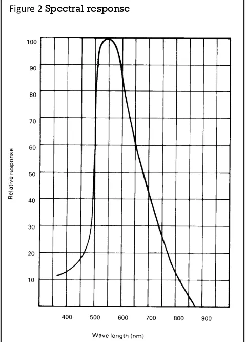
● Wide spectralresponse
● Lowcost
● Wideambienttemperaturerange. Circuit symbol
232-3816
*1Ftc=10.764 lumens
2
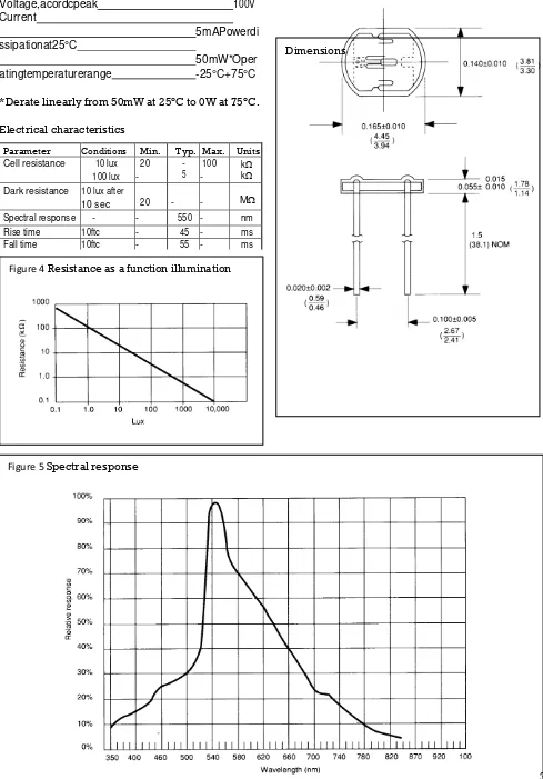
Figure 1 Power dissipation derating Figure 3 Resistance as a function of illumination
Absolute maximum ratings
Voltage,acordcpeak 100V
Current
5mAPowerdi ssipationat25°C
50mW*Oper
atingtemperaturerange -25°C+75°C
*Derate linearly from 50mW at 25°C to 0W at 75°C.
Electrical characteristics
232-3816
3
Figure 4 Resistance as a function illumination
Dimensions
Figure 5 Spectral response
Parameter Conditions Min. Typ. Max. Units
Cell resistance 10 lux
100 lux 20 -
- 5
100 -
k k Dark resistance 10 lux after
10 sec 20 - - M
Spectral response - - 550 - nm
Rise time 10ftc - 45 - ms
232-3816
Typical application circuits
TheinformationprovidedinRStechnicalliteratureisbelievedtobeaccurateandreliable;however,RSComponentsassumesnoresponsibilityforinaccuracies
oromissions,orfortheuseofthisinformation,andalluseofsuchinformationshallbeentirelyattheuser’sownrisk.NoresponsibilityisassumedbyRSComponentsforanyinfringementsofpaten tsorotherrightsofthirdpartieswhichmayresultfromitsuse. SpecificationsshowninRSComponentstechnicalliteraturearesubjecttochangewithoutnotice.
RSComponents,POBox99,Corby,Northants,NN179RS Telephone: 01536201234
AnElectrocomponentsCompany © RS Components1997
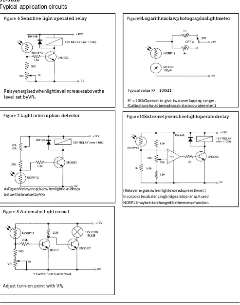
Figure 6 Sensitive light operated relay
Relayenergisedwhenlightlevelincreasesabovethe level set byVR1
Figure9Logarithmiclawphotographiclightmeter
Typical value R1 = 100k
R2 = 200kpreset to give two overlapping ranges.
(Calibrationshouldbemadeagainstanaccuratemeter.)
Figure 7 Light interruption detector
AsFigure6relayenergisedwhenlightleveldrops belowthelevelsetbyVR1
Figure 8 Automatic light circuit
Adjust turn-on point with VR1
Figure10Extremelysensitivelightoperatedrelay
(Relayenergisedwhenlightexceedspresetlevel.) Incorporatesabalancingbridgeandop-amp.R1and
T
T
h
h
i
i
c
c
k
k
F
F
i
i
l
l
m
m
T
T
e
e
c
c
h
h
n
n
o
o
l
l
o
o
g
g
y
y
–
–
S
S
e
e
n
n
s
s
o
o
r
r
A
A
p
p
p
p
l
l
i
i
c
c
a
a
t
t
i
i
o
o
n
n
s
s
telecontrolli S.r.l. Web Site: www.telecontrolli.com
1 of 6
RAINSENSOR
In this document we would describe an easy interface to use the Telecontrolli capacitive rain sensor.
Telecontrolli rain sensor is made of thick- film technology.
It is made up of three parts:
Capacitivesensor
Heatergenerator
Temperature sensor
On the top side you can find the capacitive sensor. This side part is exposed to the natural agents (rain) while on the bottom side there are the heater generator, the temperature sensor and the connection interface (sixpads). Each function of the rain sensor has stand-alone connections compared to the other in the same mode; so the user has more flexibility in the design of hardwareinterface.
The capacitive sensor has a rain sensitive area, which in dry conditions assumes the nominal value. Moreover in presence of the rain, the capacitance goes to high values compared to dry conditions and the ratio changing is over 300%.
In the table_1 is explained how the capacitance changes in the ratio of percentage of the sensitive area when covered byrain.
Sensitive area
Capacitanc
e
Ratio
Capacitanc
e
% Dry
%
water
pF
%
100
0
100
0
75
25
176
76
50
50
232
232
0
100
≥359
≥359
T
T
h
h
i
i
c
c
k
k
F
F
i
i
l
l
m
m
T
T
e
e
c
c
h
h
n
n
o
o
l
l
o
o
g
g
y
y
–
–
S
S
e
e
n
n
s
s
o
o
r
r
A
A
p
p
p
p
l
l
i
i
c
c
a
a
t
t
i
i
o
o
n
n
s
s
telecontrolli S.r.l. Web Site: www.telecontrolli.com
2 of 6
RAINSENSOR
To read the changing of sensor capacitance, we may adopt two strategies:
Frequency measurements (countermode)
Pulse measurements (timermode)
The simplest hardware which satisfies both strategies is a low cost microcontroller and few other parts. In the diagrams_1 are showed the two hardware strategies for the capacitive sensor interface.
diagrams_1
On the bottom side of “rain sensor” you have one temperature sensor like NTC by Epcosp/nB57620C0102Kwith a nominal resistance value of 1000 Ohm @ 25°C.
This sensor may be used to monitor the environment temperature and to control the heather generator to avoid frost and dump.
+5V
C2
R8
TCrainsensor U2A
SENS2 uC_counter 6 4 5 +5V R9
TC rain sensor SENS3
1 uC_COMP
T
T
h
h
i
i
c
c
k
k
F
F
i
i
l
l
m
m
T
T
e
e
c
c
h
h
n
n
o
o
l
l
o
o
g
g
y
y
–
–
S
S
e
e
n
n
s
s
o
o
r
r
A
A
p
p
p
p
l
l
i
i
c
c
a
a
t
t
i
i
o
o
n
n
s
s
telecontrolli S.r.l. Web Site: www.telecontrolli.com
3 of 6
RAINSENSOR
In the table_2 is reported the Epcos R/T characteristic (resistance/temperature).
T ( °C )
Rnom
( Ohm )
Rmin
( Ohm
)
Rmax
( Ohm )
-5
3564
3068
4061
0
2832
2457
3206
5
2267
1983
2552
10
1829
1611
2046
15
1486
1318
1653
20
1215
1086
1344
25
1000
900,0
1100
30
828,2
740,2
916,1
35
689,9
612,8
767,0
40
577,8
510,2
645,5
45
486,6
427,1
546,1
50
411,8
359,4
464,3
55
350,2
303,9
396,5
60
299,2
258,2
340,2
65
256,7
220,4
293,1
70
221,2
188,9
253,5
75
191,4
162,6
220,1
80
166,2
140,5
191,9
85
144,8
121,9
167,8
T
T
h
h
i
i
c
c
k
k
F
F
i
i
l
l
m
m
T
T
e
e
c
c
h
h
n
n
o
o
l
l
o
o
g
g
y
y
–
–
S
S
e
e
n
n
s
s
o
o
r
r
A
A
p
p
p
p
l
l
i
i
c
c
a
a
t
t
i
i
o
o
n
n
s
s
telecontrolli S.r.l. Web Site: www.telecontrolli.com
4 of 6
RAINSENSOR
In the diagram_2 is showed a simple method for the NTC conditioning.
diagram_2
To drive the heather you need only one low cost NPN transistor with Ic ≤ 500mA / VCE ≥ 25V for 12V standard
bus voltage.
The nominal resistance is 42 Ω and in this condition the current is I= 0.285A. It produces a power of P=3.43W. In
the table_3 is reported the time that occurs to the heather to rise different temperatures of rain sensor. The test has been done on a capacitive sensor with a dry surface.
∆
t ( sec
)
°C
Sensor
Substrat
e
R_NTC
( Ohm )
∆
t ( sec
)
°C
Sensor
Substrat
e
R_NTC
( Ohm )
0
27
930
90
76.
5
188
15
41
550
105
78
175
30
54
360
120
79
169
45
62
280
135
81.
5
163
60
68.5
238
150
82.
5
160
75
73.5
206
165
83.
5
156
T
T
h
h
i
i
c
c
k
k
F
F
i
i
l
l
m
m
T
T
e
e
c
c
h
h
n
n
o
o
l
l
o
o
g
g
y
y
–
–
S
S
e
e
n
n
s
s
o
o
r
r
A
A
p
p
p
p
l
l
i
i
c
c
a
a
t
t
i
i
o
o
n
n
s
s
telecontrolli S.r.l. Web Site: www.telecontrolli.com
5 of 6
RAINSENSOR
table_3
To estimate the time/power (Joule) that needs to evaporate some grams of water it is possible to use the approximative formula:
Time ( sec ) = grams_of_ humidity * 663
Conclusion
The use of the Telecontrolli rain sensor is the simplest way to design your own applications.
telecontrolli S.r.l. Web Site: www.telecontrolli.com
6 of 6 C1
R1
R2 R3
TC rain sensor
SENS1 R4
8
7
U1
VCC
PCI NT/RESET/ ADC0/PB5 1
PCI NT3/CLKI/ADC3/PB3 2
6 +5V 12 V 4 CN1 5
R5 +5V 12 V
Q1 R6 R7 D1 CN2 1 2
RAINSENSOR
+5V +5V
IndiceRevisioni :
Disegnato
A. Cennerazzo
Title RAI N SENSORI NTERF ACE
Si ze A4
Docume nt Number
440016223
Rev Draf t
Date: Mo nday , Nov e mber 03,2008 Sheet 1 of 1