Received January 6th, 2015, Revised August 9th, 2016, Accepted for publication October 22nd, 2016. Copyright © 2016 Published by ITB Journal Publisher, ISSN: 2337-5760, DOI: 10.5614/j.math.fund.sci.2016.48.3.4
Novel Ternary CoFe
2O
4/CuO/CoFe
2O
4as a Giant
Magnetoresistance Sensor
Ramli1, Ambran Hartono2, Edi Sanjaya2, Ahmad Aminudin3, Khairurrijal4,
Freddy Haryanto4, Cuk Imawan5 & Mitra Djamal4,6
1Department of Physics, Faculty of Mathematics and Natural Sciences, Universitas Negeri Padang, Jalan Prof. Hamka, Padang 25131, Indonesia 2Department of Physics, Universitas Islam Negeri Syarif Hidayatullah Jakarta,
Jalan Ir. H. Juanda 95, Ciputat, Banten 15412, Indonesia
3Department of Physics Education, Faculty of Mathematics and Natural Sciences Universitas Pendidikan Indonesia, Jalan Dr. Setiabudi 229, Bandung 40154, Indonesia
4Department of Physics, Faculty of Mathematics and Natural Sciences, Institut Teknologi Bandung, Jalan Ganesha 10, Bandung 40132, Indonesia
5Department of Physics, Faculty of Mathematics and Natural Sciences, Universitas Indonesia, Kampus UI Depok, Jawa Barat 16424, Indonesia
6Department of Physics, Institut Teknologi Sumatera, Jalan Terusan Jenderal Ryacudu, Lampung Selatan 35365, Indonesia
E-mail: [email protected]
Abstract. This paper reports the results of a study relating to the synthesis of a novel ternary CoFe2O4/CuO/CoFe2O4 thin film as a giant magnetoresistance (GMR) sensor. The CoFe2O4/CuO/CoFe2O4 thin film was prepared onto silicon substrate via DC magnetron sputtering with the targets facing each other. X-ray diffraction was used to determine the structure of the thin film and a 4-point method was used to measure the MR ratio. The GMR ratio is highly dependent on the ferrimagnetic (CoFe2O4) and nonmagnetic (CuO) layer thickness. The maximum GMR ratio at room temperature obtained in the CoFe2O4/CuO/CoFe2O4 thin film was 70% when the CoFe2O4 and the CuO layer had a thickness of 62.5 nm and 14.4 nm respectively.
Keywords: CoFe2O4; CuO; ferrimagnetic; giant magnetoresistance sensor; magnetic
sensor; spintronics.
1
Introduction
on GMR material is increasing due to today’s computers requiring large-capacity storage media at a small size [11]. Ferrite is a candidate as a magnetic oxide material that can potentially be used as a constituent of GMR layers [12,13]. Ferrite is included in the kind of magnetic oxide that has ferrimagnetic properties and has a Curie temperature above room temperature. It is well known that for temperatures below the Curie temperature, ferrimagnetic materials exhibit the same behavior as ferromagnetic materials, which have a total magnetic moment that is not zero, so at room temperature they show spontaneous magnetization, consisting of saturated magnetic domains and hysteresis phenomena [14].
In this study, we used a cobalt ferrite (CoFe2O4) with a Curie temperature of
520 ºC.Lee, et al. [15] have stated that CoFe2O4 has a high Curie temperature,
high saturation magnetization and good chemical stability. In addition, it is easy to prepare and relatively inexpensive. Until now, CoFe2O4 material has been
used as a constituent layer in spintronic devices, namely in a spin valve [16] and a spin filter [17], but to the best of the present author’s knowledge no study has explored the use of CoFe2O4 material as a ferimagnetic (FE) material constituent
of the GMR sandwich structure, FE/spacer/FE. CoFe2O4 is a ferrimagnetic
material and has a Currie temperature of 520 ºC and resistivity >105 Ω.m [14].
At room temperature, CoFe2O4 material will create a large number of
spin-polarized currents and make the efficiency of injection/detection of spin high [12]. These results suggest that CoFe2O4 has great potential as an electrode,
because it has a high Currie temperature, high resistivity and high spin polarization.According to Erdogan, et al. [18], at room temperature CuO is a
p-type semiconductor with a band gap of nearly 2.1 eVand resistivity at 106 Ωm
[19]. Recently, the potential of CuO as a constituent material for a giant magnetoresistant and high-temperature superconductor has been investigated [20]. In this paper, we describe the development of a novel ternary CoFe2O4/CuO/CoFe2O4 as a GMR material for magnetic sensor application. The
objective of this research was to investigate the magneto resistance effect of CoFe2O4/CuO/CoFe2O4 as a condition for application in magnetic sensors.
2
Experiments
CoFe2O4/CuO/CoFe2O4 thin film on (111) silicon substrate was prepared by DC
magnetron sputtering with the targets facing each other. In the experiment, the deposition temperature, Argon flow rate, deposition pressure, and plasma voltage were 100 ºC, 100 sccm, 0.52 torr, and 600 volt, respectively. The crystalline structure of the CoFe2O4/CuO/CoFe2O4 films was examined using an
method with a current perpendicular to the film plane. The GMR ratio was calculated using the definition
% 100% (1)
where RH is the resistance in the applied magnetic field and R0 is the resistance
without magnetic field.
3
Results and Discussion
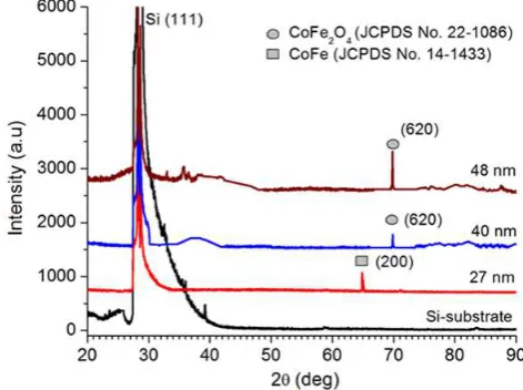
The XRD pattern of the CoFe2O4 thin films grown on Si substrate under the
same conditions for different thicknesses is shown in Figure 1. The diffraction peak at around 70,9° corresponds to the (620) plane of CoFe2O4. It can be seen
that the intensity of the (620) peak varied with the film thickness.
Figure 1 Diffraction patterns of CoFe2O4 film grown on Si (111) substrate for varied CoFe2O4 layer thicknesses. X-ray wavelength is λ = 1,54056 Ǻ.
At a thickness of 27 nm, the CoFe2O4 peak dissapeared. The diffraction peak at
around 65º corresponds to the diffraction on the (200) plane of CoFe. At a thickness of 27 nm there was no formation of CoFe2O4 film yet, which is
believed to be due to the oxygen attached to the substrate during sputtering being eroded back. The phase of CoFe2O4 began to appear at a thickness of 40
nm, so for the manufacture of GMR thin film, the thickness of the CoFe2O4 film
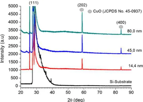
Figure 2 Diffraction patterns of CuO film grown on Si (111) substrate for varied CuO layer thicknesses. X-ray wave length is λ = 1,54056 Ǻ.
Figure 2 shows the XRD patterns of CuO thin films grown on Si substrate under the same conditions for different thicknesses. It shows that the CuO thin film had diffraction plane (202) at 58.3º and (400) at 83.6º. These diffraction peaks correspond to JCPDS card no. 45-0937. The intensity of the (202) peak strongly varied with film thickness
Figure 3 Diffraction patterns of CoFe2O4/CuO/CoFe2O4 for some variations in thickness of the CoFe2O4 layer with the thickness of the CuO layer fixed at 14.4 nm. In the experiment we used an X-ray wavelength of λ = 1,54056 Ǻ [21].
After it was known that the CoFe2O4 and CuO thin films had been grown on the
Si (111) substrate, each layer was used as a constituent of the CoFe2O4/
CuO/CoFe2O4 trilayer. The ternary CoFe2O4/CuO/CoFe2O4 was further
investigated under variation of the CoFe2O4 layer thickness while the CuO layer
CoFe2O4/CuO/CoFe2O4 for different CoFe2O4 layer thicknesses as previously
obtained [21].
The diffraction peaks that appear in Figure 3 are Si (111), CuO (110) (JCPDS card no. 45-0937) and CoFe2O4 (440) (JCPDS card no. 22-1086), at a 2θ angle
of 28.4º, 32.4º, and 62.5º, respectively. The crystal orientation of the CoFe2O4/Si film (Figure 1) differed from the CoFe2O4 in the trilayer (Figure 3),
which occurs because of differences in the structure and morphology of the material substrate. Axelsson, et al. [22] have shown that the structure and
magnetic properties of thin-layer CoFe2O4 are influenced by the type of
substrate material.
The GMR effect is very sensitive to the thickness of each constituent layer. It is associated with the spin dependent on electron scattering, which affects the GMR ratio. This effect may appear significantly when the mean free path of the conduction electrons in the material is greater than the thickness of the materials used. Therefore, the GMR ratio is greatly influenced by the thickness of the composer layer of the GMR material. Below, the influence of CuO and CoFe2O4 layer thickness on the GMR ratio will be investigated further.
3.1
Effect of CuO layer Thickness on GMR Ratio
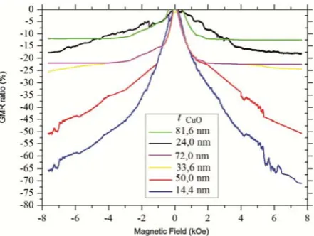
Figure 4 shows the GMR ratio of CoFe2O4/CuO/CoFe2O4 under variation of
CuO thickness. It was found that the magnetoresistance ratio was negative, which means a decline in resistance when the magnetic field used increased. Furthermore, it was also found that the GMR ratio was reduced when the layer thickness of the CuO increased, as shown in Figure 4.
Theoretically, the conductivity of the GMR layer becomes very dominant when the CuO thickness increases, so that the spin-dependent scattering becomes ineffective and consequently the GMR ratio is reduced. However, the reduced value of the GMR ratio is not linear, but follows damped oscillations, as shown in Figure 5.
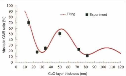
Figure 5 Dependence of the absolute value of the GMR ratio on the thickness of the CuO layer for CoFe2O4/CuO/CoFe2O4 with CoFe2O4 layer thickness fixed at 62.5 nm. Fitting equation: GMR ratio = a+b{exp[-tCuO/40]/[1+( tCuO /125)]},
where a = 20 and b = 100% (all GMR values are negative).
The oscillations shown in Figure 5 were approached by curve fitting. It can be seen that the absolute value of the GMR ratio oscillates against the CuO spacer layer thickness and the oscillation peak also decays exponentially. Thus, when fitting the data, the oscillation part was approximated by cosine functions, while the decay of the oscillation peak was approximated by an exponential function. The magnetoresistance ratio curve satisfies the following fitting equation:
2
the interface scattering between the ferrimagnetic and nonmagnetic layers and the surface resistivity of spin up and spin down in the device [23].
The oscillations appear as a result of the exchange coupling between the ferromagnetic states with the antiferromagnetic state in the CoFe2O4 layer and is
caused by oscillations in the sign interlayer exchange coupling between the CoFe2O4 layers. As the layer CuO thickness increases, the obtained GMR ratio
decreases because the exchange coupling between the CoFe2O4 layers is
reduced.
3.2
Effect of CoFe
2O
4Layer Thickness on GMR Ratio
The CoFe2O4 layer thickness affects the GMR ratio of the ternary
CoFe2O4/CuO/CoFe2O4, as shown in Figure 6. The CoFe2O4 layer thickness
affects the saturation field, Hs. Increasing the thickness of CoFe2O4 will
increase this field. The saturation field is characterized by the sharpness of the peak of the GMR ratio curve. This occurs when the thickness of the CoFe2O4
layer increases and hence more and more fractions of neighboring magnetic atoms appear in the CoFe2O4 layer, so that the saturation field increases.
Figure 6 GMR ratio curves of CoFe2O4/CuO/CoFe2O4 for several variations of CoFe2O4 thickness with CuO thickness fixed at 14.4 nm [21].
Figure 6 also shows that the CoFe2O4 layer thickness affects the GMR ratio.
When the thickness of the CoFe2O4 layer increases, the GMR ratio increases as
well for thicknesses smaller than 62.5 nm.However, the GMR ratio decreases with increasing thickness of the CoFe2O4 layer when the thickness of the layer
of CoFe2O4 is greater than 62.5 nm. A graph of the absolute GMR ratio against
CoFe2O4 layer thickness is depicted in Figure 7.
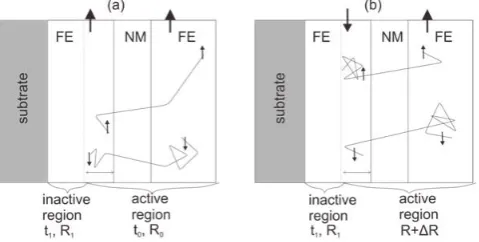
ratio. The CoFe2O4 layer is divided into an active and an inactive part, where
the active part will make a major contribution to the GMR ratio while the inactive part will shunt the current so that the GMR ratio is reduced. We refer to the work of Dieny, et al. [25] in which they describe a phenomenological theory
of the GMR in a spin valve structure.
Figure 7 The dependence of the absolute GMR ratio on the thickness of the CoFe2O4 layer for CoFe2O4/CuO/CoFe2O4 with the CuO layer thickness of fixed at 14.4 nm (all GMR values are negative).
As we know, electrons crossing the GMR layer have two spin directions: spin up (↑) and spin down (↓). In a state of parallel magnetization (Figure 8(a) ), the electrons with spin up do not undergo significant scattering in the second ferrimagnetic layer, making it easy to pass through the layer GMR, analogous to a resistor with a small resistance. Meanwhile, electrons with spin down will have a lot of scattering in crossing the GMR layer, as indicated by a large resistance.
In a state of antiparallel magnetization (Figure 8(b)), electrons with spin up have a lot of scattering in the first ferrimagnetic layer and a small amount of scattering in the second ferrimagnetic layer. Meanwhile, electrons with spin down are slightly scattered in the first ferrimagnetic layer and have a lot of scattering in the second ferrimagnetic layer.
As shown in Figure 7, the maximum GMR ratio value occurred when the thickness of the CoFe2O4 layer was 62.5 nm. With CoFe2O4 thickness below the
maximum value, the GMR ratio increases with increasing thickness of the CoFe2O4, which is caused by the appearance of the inactive part in the CoFe2O4
layer. Thus, the resistance of the GMR layer is solely influenced by the spin-dependent scattering, but after reaching the maximum, the GMR ratio is reduced due to the emergence of the active part in the GMR structure, which shunts the current. In this state, the resistance of the GMR structure is derived from the resistance of the inactive part connected in parallel to the resistance of the spin-dependent scattering.
The decrease in the absolute value of the GMR ratio at a greater CoFe2O4 layer
thickness is due to the increased current shunting in the inactive part of the CoFe2O4 layer. In the inactive part, the density of the current shunts the
conductance depending on the magnetization alignment in the inner layer of the CoFe2O4. Consequently, the GMR ratio decreases with increasing CoFe2O4
layer thickness.
4
Conclusions
In this study, synthesis of a novel ternary CoFe2O4/CuO/CoFe2O4 thin film was
successfully conducted using DC magnetron sputtering with the targets facing each other. These materials demonstrated the GMR phenomenon at room temperature with a maximum GMR ratio of 70% when the CoFe2O4 layer was
62.5 nm thick and the CuO layer was 14.4 nm thick.
Acknowledgements
The authors would like to thank BOPTN Institut Teknologi Bandung 2014 and
the Institute for Research and Community Service, Universitas Islam Negeri
(UIN) Syarief Hidyatullah Jakarta 2014 for supporting this work. This work
was also partially support by Research Incentive on National Innovation System (SINas), Ministry of Research, Technology, and Higher Education of the
References
[1] Bibes, M. & Barthelemy, A., Oxides Spintronics, IEEE Trans. Electron.
Devices, 54(5), 1003, 2007.
[2] Fert, A., Nobel Lecture: Origin, Development, and Future of Spintronic,
Rev. Mod. Phys., 80(4), pp. 1517-1530, 2008.
[3] Grundberg, P.A., Spintronics: Towards Devices with Lower Energy
Consumption, in Proc. 10th IEEE International Conference on
Nanotechnology Joint Symposium, Yeom, G.Y., Ghosh, A., Wang, Z. (Eds), pp. 3-3, 2010.
[4] Sun, D., Ehrenfreund, E. & Vardeny, Z.V., The First Decade of Organic Spintronic Research, Chem. Commun., 50, pp. 1781-1793, 2014.
[5] Baibich, M.N., Broto, J.M., Fert, A., Nguyen van Dau, F., Petro, F., Eitenne, P., Creuzet, G., Friederich, A. & Chazelas, J., Giant Magnetoresistance of (001)Fe/Cr(001) Magnetic Superlattice, Phys. Rev.
Lett., 61, pp. 2472-2475, 1988.
[6] Binasch, G., Grunberg, P., Saurenbach, F. & Zinn, W., Enhanced Magnetoresistance in Layered Magnetic Structures with Antiferromagnetic Interlayer Exchange, Phy. Rev. B, 39, pp. 4828-4830,
1989.
[7] Daughton, J., Brown, J., Beech, R., Pohm, A. & Kude W., Magnetic Field Sensors using GMR Multilayer, IEEE Trans. Magn., 30(6), pp.
4608-4610, 1994.
[8] Reig, C., Beltran, M.D.C. & Munoz, D.R., Magnetic Field Sensors Based on Giant Magnetoresistance (GMR) Technology: Application in Electrical Current Sensing, Sensors, 9, pp. 7919-7942, 2009.
[9] Wood, R., Future Hard Disk Drive Systems, J. Magn. Magn. Mater., 321(100), pp. 555-561, 2009.
[10] Tehrani,S., Chen, E., Durlam, M., Zhu, T. & Goronlun, H., High Density Nonvolatile Magnetoresistive RAM, in Proc. of International Electron Devices Meeting (IEDM’96), Hillenius, S., (Ed), pp. 193-196, 1996.
[11] Shinjo, T. (Eds), Nanomagnetism and Spintronics, Elsevier, pp. 1-13,
2009.
[12] Tezuka, N., New Materials Research for High Spin Polarized Current, J.
Mag. Magn. Matter., 324, pp. 3588-3592, 2012.
[13] Moussy, J.P., From Epitaxial Growth of Ferrite Thin Films to Spin-polarized Tunnelling, J. Phys. D: Appl. Phys., 46(14), 143001, 2013.
[14] Culity, B.D. & Graham, C.D., Introduction to Magnetic Materials, John
Wiley & Sons, Inc., pp. 183-189, 2009.
[15] Lee, J., Park, J.Y., Oh, Y. & Kim, C.S., Magnetic Properties of CoFe2O4 Tin Films Prepared by A Sol-gel Method, J. Appl. Phys., 84(5), pp.
[16] Matsuda, H. & Sakakima, H., Magnetoresistance Curves of Spin Valves using the (110) Cobalt Ferrite Pinning Layer, J. Phys. D: Appl. Phys., 44(10), 105001, 2011.
[17] Matzen. S., Moussy. J.P., Mattana, R., Bouzehouane. K., Deranlot. C. & Petroff. F., Nanomagnetism of Cobalt Ferrite-based Spin Filters Probed by Spin-Polarized Tunneling, Appl. Phys. Lett., 101(4), 042409, 2012.
[18] Erdogan, Y.I. & Gulu, O., Optical and Structural Properties of CuO Nanofilms: Its Diode Application, Journal of Alloys and Compounds, 492(1), pp. 670-675, 2010.
[19] Jundale, D.M., Joshi, P.B., Sen, S. & Patil, V.B., Nanocrystalline CuO Thin Films: Synthesis, Microstructural and Optoelectronics Properties, J.
Matter. Sci.: Mater Electron, 23(8), pp. 1492-1499, 2012.
[20] Zhang, Q., Zhang, K., Xu, D., Yang, G., Huang, H., Nie, F., Liu, C. & Yang, S., CuO Nanostructures: Syntesis, Characterization, Growth Mechanism, Fundamental Properties, and Applications, Progress in
Materials Science, 60, pp. 208-337, 2014.
[21] Djamal, M., Ramli., Khairurrijal & Haryanto, F., Development of Giant Magntetoresistance Material Based on Cobalt Ferrite, Acta Physica
Polonica A, 128(2-B), B19-B22, 2015.
[22] Axelsson, A.K., Aquesse. F., Tileli. V., Valant, M. & Alford, N.M.,
Growth Mechanism and Magnetism of CoFe2O4 Thin Films; Role of the Substrate, J. Alloys and Compound, 578, pp. 286-291, 2013.
[23] Yamagishi, Y., Honda, S., Inoue, J. & Itoh, H., Numerical Simulation of Giant Magnetoresistance in Magnetic Multilayers and Granular Films,
Phys. Rev. B, 81, 054445, pp.1-5, 2010.
[24] Bruno, P. & Chappert, C., Oscillatory Coupling between Ferromagnetic Layers Separated by a Nonmagnetic Metal Spacer, Physical Review
Letters, 67(12), pp. 1602-1606, 1991.
[25] Dieny, B., Humbert, P., Speriosu, V.S., Metin, S., Gurney, B.A., Baumgart, P. & Lefakis, H., Giant Magnetoresistance of Magnetically Soft Sandwiches: Dependence on Temperature and on Layer Thicknesses,
![Figure 6 CoFeGMR ratio curves of CoFe2O4/CuO/CoFe2O4 for several variations of 2O4 thickness with CuO thickness fixed at 14.4 nm [21]](https://thumb-ap.123doks.com/thumbv2/123dok/4018100.1961520/7.595.180.403.319.490/figure-cofegmr-ratio-curves-cofe-variations-thickness-thickness.webp)