ARTEFACT MOBILE DATA MODEL TO SUPPORT CULTURAL HERITAGE DATA
COLLECTION AND INTERPRETATION
Z.S.Mohamed-Ghouse a, *, D.Kelly a, A.Costello a, V.Edmonds a,
a
Sinclair Knight Merz, 452 Flinders Street, Melbourne 3000, Victoria, Australia
[email protected]
Commission WG V/2
KEY WORDS: Artefact, Data Model, RDBMS, Archaeology, mobile mapping and cultural heritage
ABSTRACT:
This paper discusses the limitation of existing data structures in mobile mapping applications to support archaeologists to manage the artefact (any object made or modified by a human culture, and later recovered by an archaeological endeavor) details excavated at a cultural heritage site. Current limitations of data structure in the mobile mapping application allow archeologist to record only one artefact per test pit location. In reality, more than one artefact can be excavated from the same test pit location. A spatial data model called Artefact Mobile Data Model (AMDM) was developed applying existing Relational Data Base Management System (RDBMS) technique to overcome the limitation. The data model was implemented in a mobile database environment called
SprintDB Pro
which was in turn connected to ArcPad 7.1 mobile mapping application through Open Data Base Connectivity (ODBC). In addition, the design of a user friendly application built on top of AMDM to interpret and record the technology associated with each artefact excavated in the field is also discussed in the paper. In summary, the paper discusses the design and implementation of a data model to facilitate the collection of artefacts in the field using integrated mobile mapping and database approach.
* Corresponding author.
1. INTRODUCTION
Archaeologists conduct a range of cultural heritage management activities for a variety of clients. They are routinely engaged in assessing the cultural heritage significance of areas scheduled for high impact activities, such as the construction of roads, railways and pipelines. This can involve developing sophisticated site prediction models and undertake high resolution excavation programs. Each artefact recovered during excavation can reveal historical land use of the area, and of the people who once lived there, sometimes thousands of years previously. The accurate recording of data relating to any artefact recovered during excavation is essential. Details such as the depth at which artefacts are found, how they are formed, the state of artefact preservation and the commonality of the artefact to the area being crucial to the understanding of the history, and pre-history of the landscape.
Artefacts (see figure 1) are objects culturally modified in some way for human use. Stone artefacts begin by chipping at a ‘core’ in a specific way to ‘flake’ off a smaller piece to be used to cut or scrape other pieces of stone, bone, flesh or wood, to create other sorts of artefacts. The core is the primary object, a ‘flake’ is the secondary object. A flake can then be further manipulated to create a ‘tool’, which is a stone artefact made for a specific purpose or action, for example, hammering, grinding, chopping or scraping.
Figure 1 Sample artefact excavated at the site
There is a long history of debate in archaeological artefact analysis, produces many different terminologies, which can add confusion if more than one archaeologist is analysing artefacts for the same project. Creating a database with restricted standardized terminology was seen as a good way to overcome this and allowed multiple archaeologists accessing data from a single database.
2. NEED FOR STUDY
A test pit (generally 1m by 1m in size) is excavated in the field to test the presence or absence of cultural material, or artefacts. The test pit is represented as a feature (point) in the mobile
mapping application. A “feature” can be defined as the digital object associated with a geographical entity (Usery, 1996). The next step is to record the information about each excavated artefact from the test pit. This information had been stored in the test pit’s feature attribute table, inherent limitations of the feature attribute table means that only one record per test pit (one-to-one relationship) can be maintained. In reality, more than one artefact can be excavated from the same pit (one-to-many relationship) which limits the user from storing information regarding additional artefacts in the same test pit’s feature attribute table. Thus, standard GIS software used in mobile mapping application is limited to store only one record for each feature. In order to store information for more than one artefact excavated from the same test pit, we need a database approach that allows one-to-many relationship. In addition, the user needs to interpret and record the technology associated with each artefact excavated in the field. The reason interpretation must occur in the field is due to the cultural sensitivities of some Indigenous Australian groups, archaeologist are often not allowed to remove cultural heritage from the excavation site. This sensitivity is also reinforced by legislation in some parts of Australia (Aboriginal Heritage Act 2006, 2006).
Based on the above discussion we can broadly classify the following objectives:
Develop a data model to support one-to-many relationship for the mobile data capture, and;
Develop a tool to interpret the artefact technology using the mobile device in the field.
3. ARETEFACT MOBILE DATA MODEL This section develops a formal data model of artefact storage in a mobile mapping database. The model is based on Relational Data Base Management System (RDBMS), and is termed Artefact Mobile Data Model (AMDM). The key idea behind AMDM is to provide the archaeologist an integrated spatial (test pit) and non-spatial (artefacts information) database in the mobile mapping application.
The non-spatial data being stored in the database detailing attributes of the artefact, can be used to classify and analyse the artefacts later, as well as producing an easy method (queries) to detect patterns in the archaeological record.
3.1 Database design
A relation scheme is a common structure in relational database design that specifies the name of the table (relation), followed in parentheses by the names and domains for any attributes in that table [e.g. tablename(attribute1: integer, attribute2: string)] (Mohamed Ghouse and Duckham, 2009). This section uses
relation schemes to describe the general design of the AMDM. The relation TEST_PIT has the details about the location of the test pit and additional attributes associated with the test pit. The unique identifier sid relates to the location of the test pit. The
geometry column in the TEST_PIT relation stores the point
location obtained through GPS.
TEST_PIT
(sid, geometry, x, y,
site_type, sname, date,
dimension, max_depth,
landform, artefact_present,
no_of_artefact,photo_id,
photo_descr, comments)
One of the objectives discussed in section 3 is to provide a tool to the archeologist to interpret artefacts of various technology types. Four technologies: Flake; Core; Tool; and Other were identified as the artefacts categories by the archeologist. The following relational scheme TECH_FLAKE provides the platform for the archeologist to store details of the technology type flake.
The unique identifier flake_id identifies the artefact. The foreign key sid (site identifier) in the TECH_FLAKE relation relates to the sid in the TEST_PIT relation. The other attributes such as physical properties of the artefact and photos are recorded as shown in the above relation TECH_FLAKE.
The structure of the relations TEST_PIT and TECH_FLAKE
provides the flexibility to the archeologist to store more than one artefact for each test pit by overcoming the limitation cited in the
section 2. The example query1 shown will retrieve all flake artefacts excavated from the first test pit at the cultural heritage site. The SELECT keyword in the query1 specifies which columns are to appear in the output; the asterisk * refers to all columns in the table; the FROM keyword specifies the table to be used; and the WHERE clause filters the result subject to some condition (Connolly et al., 1999).
Query1:
SQL Statement
SELECT tech_flake.*
FROM test_pit, tech_flake
WHERE test_pit.sid = tech_flake.sid
AND test_pit.sid = 1
The results of query1 are shown in table 1.
Table 1: Query 1 results
|flake_id |sid|form |condition|cortex |...
|1| 1|Broken |Disturbed |Absent |...
|2| 1|Regular |Disturbed |Present|...
|3| 1|Regular |Disturbed |Absent |...
Following relations schemes TECH_CORE, TECH_TOOL and
TECH_OTHER for artefact technology categories core, tool and
other were developed subsequently.
TECH_TOOL(tool_id, sid, type, used_wear, platform, material, termination_details, dorsal_scar, over_hang_removal,
As discussed the sid (site identifier) was used as the key relating the artefact records in the TECH_FLAKE, TECH_CORE,
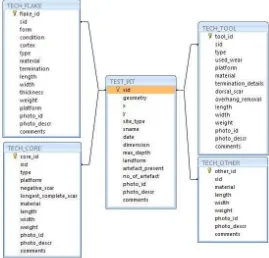
TECH_TOOL, TECH_OTHER tables to the test pit (point
feature), in TEST_PIT, they were found in, this is clearly depicted in the relationship diagram in figure 2. The data model not only allows storage of many artefacts per site but also, information on many types of artefacts. The relationship between TEST_PIT and the artefact tables provides further flexibility to ensure that the archeologists were able to capture details about the artefacts found in the test pit efficiently and effectively.
Figure 2. Relationship diagram of database International Archives of the Photogrammetry, Remote Sensing and Spatial Information Sciences, Volume XXXIX-B5, 2012
4. IMPLEMENTATION 4.1 Technology
GeoExplorers XT Trimble mobile device with sub meter positional accuracy was used in the field to capture both spatial (test pit as point feature) and non-spatial data (artefact technology).
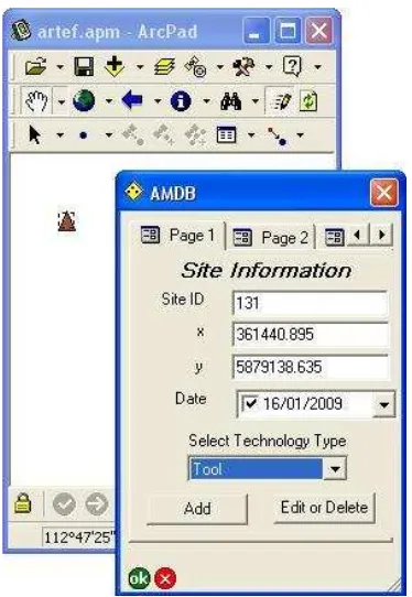
The relational schemes developed in the previous section were implemented using SprintDB pro database supported for mobile devices. The advantage of SprintDB pro database is that the mobile database can be automatically synchronised to an MS Access desktop database after the field visit which reduces the manual data transfer from the mobile device to a desktop database and allows additional processing in post field work. The SprintDB pro database and the ArcPad application were loaded on to the GeoExplorers XT Trimble mobile device. ArcPad studio was used to customise the forms. The data entered in the ArcPad forms shown in figure 3 and 4 is stored in the mobile database through ODBC. Figure 3 shows the location of the test pit and customised form to enter the details of the test pit which depicts the TEST_PIT relation discussed in section 3.1. Similarly figure 4 represents the relation
TECH_TOOL in the ArcPad customized form.
Figure 3 Customised form depicting the location of the test pit
Figure 4 Form to interpret the artefact identified with technology tool type
4.2 Post field usage- Artefact analysis
Artefact analysis has previously been undertaken using a pen and paper in the field and a fairly simple spreadsheet in the laboratory. This has several inherent drawbacks, including the time spent in double handling of information as well as the lack of conformity in terminology. By restricting the vocabulary to an agreed standardised set of analytical terms based on accepted archaeological references, greater clarity is achieved.
The ability to synchronise the SprintDB pro field database to the MS Access desktop database, allowed for efficient analysis of the data to be conducted and effective statistics to be output to assist in the reporting of the works.
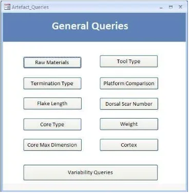
Within the MS Access desktop database an interface (figure 5) was developed to allow review, further comments and interpretation to be made post field work if needed. The interface was designed to take advantage of the relations between the tables, so that on selecting an area of interest and a test pit (whose non-spatial information could be updated if needed) artefacts related to the test pit are available for update or modification to facilitate further interpretation. The queries to extract the derivative information were also designed into a simple interface (figure 6) for the archaeologists. The inclusion of the user interface made the operation of the database more user friendly for the archaeologists. It also allowed checks and per-set options to ensure valid data was entered.
Figure 5. Test pit desktop database user interface
Figure 6. Interface to extract derivative information
The processing to deliver the derivative information to the archeologists was performed by a number of queries. These included comparisons of artefacts found over a number of sites of significance and counts of artefact types and the materials they are made of. An example of these processing queries is the following: among all artefacts found at a particular test pit, show the artefacts for each material and artefact category combination.
Query2 below demonstrates how this was achieved and shows a portion of a formatted table based on the results of this query. These queries could also provide aggregated data across any area of interest or the entire study area, this is modified through
the WHERE clauses.
Query2:
SQL Statement
SELECT X.sid, X.geometry, X.material
X.Core, X.Flake, Y.Misc, Y.Tool
FROM ( SELECT A.sid, A.geometry,
A.material, A.Core, B.Flake
FROM
(SELECT sid,geometry, material,
Count(material) As Core ( SELECT C.sid, C.geometry, C.material, C.Misc, D.Tool
Table 2: Formatted Table Based On Query Results
|sid|Material |Core |Flake |Misc |Tool|
|1|Andesite |15 |4 |2 |0 |
|1|Chert |1 |9 |0 |0 |
|1|Hornfels |0 |4 |1 |0 |
In the example shown in table 2, a comparison of material type versus artefact type is shown. This is relevant to archaeologists as material and type can indicate how far from the source of the raw material the site is, what kind of behaviours and activities occurred at the site and even the type of diet preferred by the original inhabitants. For example, the prevalence of one material type at a site could mean either a cultural preference for the material or an abundance of that material in the landscape. When artefact type is considered, this can be refined, as a dominance of cores would suggest closer proximity to the source, while a dominance of flakes would indicate a greater distance.
5. SUMMARY AND DISCUSSIONS
The paper discusses, the existing data structure provided by mobile mapping applications to support the management of artefacts excavated at a cultural heritage site by archaeologists. The review identified that the archaeologists needed to store more than one artefact of differing types per site. The data structure provided in the mobile mapping application had the inherent limitation of not supporting the storage of more than one artefact per site as the data structure was designed to support one-to-one relationships. To overcome the limitation, the Artefact Mobile Data Model (AMDM) was developed using existing RDBMS technique to support storage of details for more than one artefact for each site (one-to-many relationship), and relating the artefact details directly to the test pit at the time International Archives of the Photogrammetry, Remote Sensing and Spatial Information Sciences, Volume XXXIX-B5, 2012
of capture. The data model was implemented in the mobile database and the ArcPad application was customised to support the interpretation of artefacts in the field as the cultural heritage management prerogatives do not allow the archaeologist to take the artefacts from the site.
The paper considers a site location (test-pit) as a point feature. Future design improvements include linear features such as the pattern of the artefact excavation and polygon features such as area of test pits depicting the excavation zone, needs to be included and tested in the AMDM data model.
6. REFERENCES
Aboriginal Heritage Act 2006., 2006. Part 3—Protection of Aboriginal Cultural Heritage. 23-34.
Connolly, T. M., Begg, C., Strachan, A., 1999. Database systems. 2nd Edition. Addison-Wesley.
Mohamed Ghouse, Z., Duckham, M., 2009. Integrated storage and querying of spatially varying data quality information in a relational spatial database. Transactions in GIS 13(1), 25-42.
Usery E L 1996. A feature-based geographic information system model. Photogrammetric Engineering and Remote Sensing 62: 833–838
![table [e.g. tablename(attribute1: integer, attribute2: string)]](https://thumb-ap.123doks.com/thumbv2/123dok/3235689.1396723/2.595.85.260.359.602/table-e-g-tablename-attribute-integer-attribute-string.webp)