Lampiran 2 : Listing Program
/***************************************************************** ***
This program was produced by the CodeWizardAVR V2.05.3 Standard Automatic Program Generator
© Copyright 1998-2011 Pavel Haiduc, HP InfoTech s.r.l. http://www.hpinfotech.com
Project : Version :
Date : 03/12/2013
Author : Fitri Hidayati Sinaga Company : free
Comments:
Chip type : ATMega16 Program type : Application
AVR Core Clock frequency: 12,000000 MHz Memory model : Small
// Alphanumeric LCD functions #include <alcd.h>
#include <stdio.h>
#define ADC_VREF_TYPE 0x40 // Declare your global variables here
unsigned int read_adc(unsigned char adc_input) {
ADMUX=adc_input | (ADC_VREF_TYPE & 0xff);
// Delay needed for the stabilization of the ADC input voltage delay_us(10);
// Start the AD conversion ADCSRA|=0x40;
// Wait for the AD conversion to complete while ((ADCSRA & 0x10)==0);
ADCSRA|=0x10; return ADCW; }
unsigned int x; //menghasilkan data integer yang tidak bertanda
unsigned char buflcd[16]; //penyimpanan data LCD sementara maks. 16 karakter
unsigned int intTOTAL, intADC; //menghasilkan data integer pada perintah tersebut
float flHASIL, flMEAN; //menghasilkan data bilangan berkoma
void main(void) {
// Declare your local variables here
// Input/Output Ports initialization // Port A initialization
// Func7=In Func6=In Func5=In Func4=In Func3=In Func2=In Func1=In Func0=In
DDRA=0x00;
// Port B initialization
// Func7=In Func6=In Func5=In Func4=In Func3=In Func2=In Func1=In Func0=In
// State7=T State6=T State5=T State4=T State3=T State2=T State1=T State0=T PORTB=0x00;
DDRB=0x00;
// Port C initialization
// Func7=In Func6=In Func5=In Func4=In Func3=In Func2=In Func1=In Func0=In
// State7=T State6=T State5=T State4=T State3=T State2=T State1=T State0=T PORTC=0x00;
DDRC=0x00;
// Port D initialization
// Func7=In Func6=In Func5=In Func4=In Func3=In Func2=In Func1=In Func0=In
// State7=T State6=T State5=T State4=T State3=T State2=T State1=T State0=T PORTD=0x00;
DDRD=0x00;
// Timer/Counter 0 initialization // Clock source: System Clock // Clock value: Timer 0 Stopped // Mode: Normal top=0xFF // OC0 output: Disconnected TCCR0=0x00;
// Timer/Counter 1 initialization // Clock source: System Clock // Clock value: Timer1 Stopped // Mode: Normal top=0xFFFF // OC1A output: Discon. // OC1B output: Discon. // Noise Canceler: Off
// Input Capture on Falling Edge // Timer1 Overflow Interrupt: Off // Input Capture Interrupt: Off // Compare A Match Interrupt: Off // Compare B Match Interrupt: Off TCCR1A=0x00;
// Timer/Counter 2 initialization // Clock source: System Clock // Clock value: Timer2 Stopped // Mode: Normal top=0xFF // OC2 output: Disconnected ASSR=0x00;
// External Interrupt(s) initialization
// Timer(s)/Counter(s) Interrupt(s) initialization TIMSK=0x00;
// USART initialization // USART disabled UCSRB=0x00;
// Analog Comparator initialization // Analog Comparator: Off
// Analog Comparator Input Capture by Timer/Counter 1: Off ACSR=0x80;
SFIOR=0x00;
// ADC initialization // ADC disabled
ADMUX=ADC_VREF_TYPE & 0xff; ADCSRA=0x87;
SFIOR&=0xEF;
// SPI initialization // SPI disabled SPCR=0x00;
// TWI disabled TWCR=0x00;
// Alphanumeric LCD initialization // Connections are specified in the
//puts(buflcd); putchar('\r'); //---
Lcd_clear(); lcd_gotoxy(0,0);
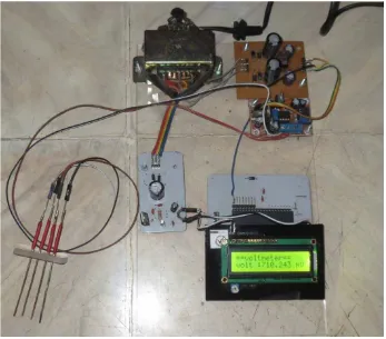
lcd_putsf("==voltmeter==");
sprintf(buflcd,"volt : %.3f mV",flHASIL); lcd_gotoxy(0,1); lcd_puts(buflcd); puts(buflcd); putchar('\r'); delay_ms(800);
Lampiran 3 :
Gambar elektroda konfigurasi Wenner