Table of Contents
Building Secure Wireless Networks with 802.11...1
Introduction...4
Who Should Read This Book...4
What You Need to Know...5
How This Book Is Organized...5
Part I: Introduction to Wireless Local Area Networks (LANs)...8
Chapter List...8
Part Overview...8
Chapter 1: Networking Basics...10
Highlights...10
Development of Computer Networks: An Overview...10
Network Types...13
Evolution of Wireless LANs: An Overview...31
A Basic Wireless LAN...32
Basic Architecture of a Wireless LAN...33
Wireless LAN Adapters...33
Are Wireless LANs Risks to Health?...43
Table of Contents
Chapter 2: Wireless LANsSummary...43
Chapter 3: The Institute of Electrical and Electronics Engineers (IEEE) 802.11 Standards...44
Overview...44
History of IEEE...44
IEEE 802 Wireless Standards...45
The 802.11 Working Group...45
The 802.15 Working Group...45
The 802.16 Working Group...46
The 802.11 Family of Standards...46
The 802.11 Standard Details...46
802.11 Security...48
Operating Modes...49
Roaming...50
The 802.11 Extensions...50
802.11b...50
802.11 a...52
802.11g...53
802.11 Shortcomings...54
Wireless Standards Comparison...55
Summary...55
Chapter 4: Is Wireless LAN Right for You?...56
Benefits of Wireless LANs...56
Deployment Scenarios...57
Small Office Home Office (SoHo)...57
Enterprise...58
Wireless Internet Service Providers (WISPs)...59
Costs Associated with Wireless LANs...61
SoHo...61
Enterprise...61
WISPs...61
Deployment Issues...61
SoHo...61
Enterprise...62
WISPs...62
Security...62
Health Concerns...63
Summary...63
Part II: Secure Wireless LANs...64
Chapter List...64
Part Overview...64
Table of Contents
Network Data Transmission and Link Security...79
Securing Network Transmission...80
Summary...86
Chapter 6: Securing the IEEE 802.11 Wireless LANs...87
Wireless LAN Security Requirements...87
Wireless LAN Operational Security Requirements...88
Wireless LAN Data Security...90
The Institute of Electrical and Electronics Engineers (IEEE) 802.11 Standard Security...90
Service Set Identifiers (SSID)...91
Wired Equivalent Privacy (WEP) Protocol...91
IEEE 802.11 WEP Protocol Weaknesses and Shortcomings...95
The Future of 802.11 Standard Security...96
Common Security Oversights...96
Wireless LAN Passwords and Usage Policies...102
Frequent Network Traffic and Usage Analysis...102
Summary...102
Part III: Building Secure Wireless LANs...103
Chapter List...103
Part Overview...103
Chapter 7: Planning Wireless LANs...104
Overview...104
Step 1: Understanding Your Wireless LAN Needs...104
Step 2: Planning the Scope of Rollout...106
Step 3: Performing Site Survey...106
Considering the Geographic Coverage Area...107
Per−Site Security Requirements...107
Profiling Wireless LAN Users and Devices...107
Step 4: Setting Up Requirements and Expectations...108
Network Bandwidth and Speed...108
Coverage Area and Range of Wireless LANs...108
Security...109
Table of Contents
Chapter 7: Planning Wireless LANsBasic Wireless LAN Hardware...109
Software...111
Conventional Hardware Requirements for Various Deployment Scenarios...112
Step 6: Evaluating the Feasibility of Wireless LANs and the Return on Investment (ROI)...113
Step 7: Communicating the Final Plan with Higher Executives and Potential Users...114
An Example of Wireless LAN Planning: Bonanza Corporation...114
Step 1: Bonanza Wireless LAN Needs...114
Step 2: Planning the Rollout...115
Step 3: Site Survey...115
Step 4: Setting Up Requirements and Expectations...116
Step 5: Estimating the Required LAN Hardware and Software...117
Step 6: Evaluating the Feasibility of Wireless LANs and Estimating Return on Investment (ROI)...117
Step 7: Communicating the Wireless LAN Deployment Plan with Executives...118
Summary...118
Chapter 8: Shopping for the Right Equipment...119
Overview...119
Making Your Wireless LAN Equipment Shopping List...119
Explore the LAN Technologies Available in the Market...120
Wireless LAN Technologies...120
Wired LAN Ethernet Equipment Technologies...120
Virtual Private Network (VPN) Gateways and Clients...121
Remote Authentication Dial−in User Service (RADIUS) Server...121
Wireless LAN Supporting Operating Systems...121
Major 802.11 Equipment Vendors and Their Products...122
Cisco Systems...122
Shopping at a Local Computer Hardware or Office Supply Store...134
Shopping Tips...134
Summary...135
Chapter 9: Equipment Provisioning and LAN Setup...136
Before We Start...136
Identifying the Wireless LAN Components...136
Wireless LAN Adapters...137
Table of Contents
Chapter 9: Equipment Provisioning and LAN SetupSetting Up Wireless LAN Adapters...145
Finishing the Access Point Configuration...150
Testing Your Standalone Wireless LAN...154
Adding More Computers to Your Standalone Wireless LAN...154
Connecting a Wireless LAN to the Internet...155
Using Multiple AP Configurations...156
Overlapping AP Configuration...156
Non−Overlapping AP Configuration...157
Setting Up Wireless LAN for the 802.11 Ad−Hoc Mode...158
Summary...159
Chapter 10: Advanced 802.11 Wireless LANs...160
High Security and Authentication−Enabled 802.11 Wireless LANs...160
The 802.1X Standard...160
Virtual Private Network for Wireless LANs...161
Building a Secure Wireless LAN with 802.1X and VPN Technology...164
Point−to−Point Wireless Connectivity between Two Sites...174
Point−to−Point Wireless Connectivity Requirements...174
Network Configuration...174
Setting Up ORiNOCO Point−to−Point Radio Backbone Kit...175
Securing the Point−to−Point Wireless Connectivity Using VPN...177
Secure Remote Access from a Wireless LAN over the Internet Using VPNs...177
Summary...178
Part IV: Troubleshooting and Keeping Your Wireless LAN Secure...179
Chapter List...179
Handling Bandwidth Congestion Due to Competing Devices...183
Upgrading Wireless LANs...184
Optimizing and Managing the Network Load through Monitoring Wireless LAN Quality...184
Summary...184
Chapter 12: Keeping Your Wireless LAN Secure...186
Table of Contents
Chapter 12: Keeping Your Wireless LAN SecureGetting Ready for Future Security Challenges...194
Summary...194
Appendix A: Wireless LAN Case Studies...196
Overview...196
Home−Based Wireless LANs: The Khwaja Family Residence...196
Background...196
The Problem...197
The Solution...197
Results...197
Future...198
A Small Corporation Wireless LAN: The Morristown Financial Group...198
Background...198
The Problem...198
The Solution...198
The Results...199
The Future...199
Campus−Wide Wireless LAN: Carnegie Mellon University...199
Background...199
The Problem...200
The Solution...200
The Results...201
Wireless Internet Service Providers: M−33 Access...201
Background...202
The Problem...202
The Solution...202
The Result...204
The Future...204
Appendix B: Installing ORiNOCO PC Card Under Various Operating Systems...205
Overview...205
Installing under Windows 98, Windows ME, and Windows 2000...205
Table of Contents
Appendix B: Installing ORiNOCO PC Card Under Various Operating Systems
D−E...221
F−I...222
K−O...224
P−R...225
S−W...227
References...229
List of Figures...230
Chapter 1: Networking Basics...230
Chapter 2: Wireless LANs...230
Chapter 4: Is Wireless LAN Right for You?...230
Chapter 5: Network Security...230
Chapter 6: Securing the IEEE 802.11 Wireless LANs...231
Chapter 7: Planning Wireless LANs...231
Chapter 9: Equipment Provisioning and LAN Setup...231
Chapter 10: Advanced 802.11 Wireless LANs...231
Appendix B: Installing ORiNOCO PC Card Under Various Operating Systems...232
List of Tables...233
Chapter 1: Networking Basics...233
Chapter 3: The Institute of Electrical and Electronics Engineers (IEEE) 802.11 Standards...233
Chapter 7: Planning Wireless LANs...233
Chapter 8: Shopping for the Right Equipment...233
Chapter 10: Advanced 802.11 Wireless LANs...233
Chapter 11: Troubleshooting Wireless LANs...233
Chapter 12: Keeping Your Wireless LAN Secure...233
List of Sidebars...234
Building Secure Wireless Networks with 802.11
Jahanzeb Khan Anis Khwaja
Wiley Publishing, Inc.
Publisher: Robert Ipsen
Executive Editor. Carol Long
Assistant Development Editor: Scott Amerman
Associate Managing Editor: Pamela M. Hanley
Editorial Manager. Kathryn A. Malm
New Media Editor: Brian Snapp
Text Design & Composition: Wiley Composition Services
This book is printed on acid−free paper.
Copyright © 2003 by Jahanzeb Khan and Anis Khwaja.
All rights reserved.
Published by Wiley Publishing, Inc., Indianapolis, Indiana
Published simultaneously in Canada
No part of this publication may be reproduced, stored in a retrieval system, or transmitted in any form or by any means, electronic, mechanical, photocopying, recording, scanning, or otherwise, except as permitted under Section 107 or 108 of the 1976 United States Copyright Act, without either the prior written permission of the Publisher, or authorization through payment of the appropriate per−copy fee to the Copyright Clearance Center, Inc., 222 Rosewood Drive, Danvers, MA 01923, (978) 750−8400, fax (978) 750−4470. Requests to the Publisher for permission should be addressed to the Legal Department, Wiley Publishing, Inc., 10475 Crosspoint Blvd., Indianapolis, IN 46256, (317) 572−3447, fax (317) 572−4447, E−mail: <[email protected]>.
572−3993 or fax (317) 572−4002.
Trademarks: Wiley, the Wiley Publishing logo and related trade dress are trademarks or registered
trademarks of Wiley Publishing, Inc., in the United States and other countries, and may not be used without written permission. All other trademarks are the property of their respective owners. Wiley Publishing, Inc., is not associated with any product or vendor mentioned in this book.
Wiley also publishes its books in a variety of electronic formats. Some content that appears in print may not be available in electronic books.
Library of Congress Cataloging−in−Publication Data:
ISBN 0−471−23715−9
Printed in the United States of America
10 9 8 7 6 5 4 3 2 1
We dedicate this book to our parents for their hard work and countless sacrifices, which helped us reach where we are today.
Acknowledgments
Although our names appear alone on the cover of this book, many people have contributed in some form or other to the book's creation. In many cases, these people are good friend of ours; and in other cases, we have never met the individuals and have conversed with them only on the phone or by email. We thank you all who helped us, as we are certain that we could not have completed this book without the help, assistance, and moral support.
We must thank Anis's wife and his children for their understanding and support while Anis was busy late nights and weekends working on the book. We also extend our thanks to Mr. A. Jalil for believing in Anis and opening a world of opportunities for him.
We thank Una Cogavin, our personal friend, who helped us edit some of the chapters at times when we were scrambling to meet the deadlines. Una provided us with feedback that helped us do a better job at writing.
Anis and I are both extremely thankful to Dr. Bob Harbort who was instrumental in our academic careers. Dr. Harbort taught us the information research process in those days when research tools like the Internet were unheard of.
We must also thank Dr. Doreen Galli Erickson, one of the best mentors on this planet, who helped us build our computer science foundation and introduced advanced computing concepts to us. We also thank Mr. Mohibullah Sheikh, the brilliant mathematician and beloved teacher, who taught us how to think critically and approach problems rationally.
Scott Amerman, our development editor at John Wiley and Sons, worked incredibly hard on the manuscripts and the overall book contents. He has been absolutely indefatigable while dealing with the manuscript changes as we worked on the manuscript at the same time. We appreciate his patience and understanding in working with two very green writers.
Michelle Ragsdale and Mark Shapiro of Davis Marrin, the public relations firm of Agere Corporation, provided us with information on Agere Wireless LAN products. We are extremely thankful to them for accommodating our needs on extremely short notice.
About the Authors
Jahanzeb Khan is Principal Engineer with RSA Security, Inc. (formerly RSA Data Security Inc.). He
is currently involved in the research and development of Wireless LAN Security standards. At RSA, he is responsible for the research and development of secure network and data communication. Before RSA, he worked at Oracle Corporation and Symantec Corporation, where he was responsible for application software development that required user authentication and security services. Jahanzeb Khan has a B.S. in Computer Science, with emphasis in computer networks and security. He is a member of IEEE International and is active in the 802.11b community. He has over 12 years experience in software and hardware development in general software and computer networks. He has authored various Internet drafts and actively participates in World Wide Web Consortium (W3C) and Internet Engineering Task Force (IETF) activities. He also participates in ongoing discussions relating to Wired Equivalent Privacy (WEP) vulnerability that affects Wi−Fi/802.11 High−Rate Wireless LANs.
Introduction
Wireless connectivity of computing devices is rapidly becoming ubiquitous and soon may be the primary, if not the only, method for many portable devices to connect with computer networks. Wireless LANs provide the easiest way to interconnect computers for both enterprise and SoHo (Small Office, Home Office) environments. First available at airport kiosks, public access has spread through airport waiting rooms, hotels, and restaurants into coffee shops, hospitals, libraries, schools, and other locations. Like any fast growing and successful technology, the phenomenal grown of wireless LANs has been fueled by a convergence of intense customer demand to access data for untethered data access, ever shrinking computing devices, and the standardization of equipment around 802.11b wireless fidelity (Wi−Fi) technology. This has resulted in achieving economies of scale, which enabled prices to go down, further fueling the demand. In this book we explore how secure wireless networks can be built using 802.11 with primary focus on secure wireless LANs.
This book is an implementer's guide to 802.11 (Wi−Fi) wireless networking for home, small offices, enterprises, and Wireless Internet Service Providers (WISPs). It includes introduction and overview of 802.11b (Wi−Fi) technology, planning and design guidelines for implementing wireless LANs, and criteria for evaluating hardware and software. We explore security features and weaknesses, as well as policy management and associated trade−offs in implementing such networks. Quality of service, bandwidth issues, compatibility with related technologies like HomeRF as well as emerging technologies and developments in wireless networking are also examined.
Building Secure Wireless Networks with 802.11 focuses on the wireless LANs that are built using
the Institute of Electrical and Electronics Engineers (IEEE) 802.11 standard. The book is a stepwise guide to building a wireless LAN. First we discuss the basics of wired LANs to help those readers who are either not familiar with LAN technologies and those who would like to gain a better understanding of LANs in general. We talk about the basics of wireless LAN by discussing the primary characteristics of a wireless LAN. We introduce the IEEE 802.11 standards and help you understand the basic differences between the IEEE wireless LAN standards. We also help you evaluate whether wireless LANs are right for you.
One of the primary motivations for writing this book was the fact that the books available at the writing of Building Secure Wireless Networks with 802.11 did not cover the important security needs
of wireless LANs. The authors of this book, given their unique perspective and experience in the computer security industry, recognize security of the wireless LAN as the key factor in determining the future of wireless LANs. In addition to the chapters dedicated to network security, we pay special attention to the security issues of both the wired LANs and that of wireless LANs throughout the book. We discuss standard IEEE 802.11 security as well as the complementary technologies that can be used to provide a robust security to a wireless LAN.
At the end of the book, we also present some real−life case studies to help you visualize the problems that you can solve using a wireless LAN, the challenges that you might face, and the outcomes of using a wireless LAN.
Who Should Read This Book
who want to deploy secure wireless LANs and need to understand the issues surrounding wireless LANs. Building Secure Wireless Networks with 802.11 is where you can find the plain−English
information you need to put Wireless LANs to work.
What You Need to Know
Every book ever written makes some basic assumptions about the reader; some require a user to have in−depth knowledge of the subject, whereas others could be written with a layman in mind.
Building Secure Wireless Networks with 802.11 is written for readers who may have different levels
of knowledge and understanding of wireless LANs. The book starts from the very basics of LAN technologies and extends the discussion to the latest available wireless LAN technologies. The book attempts to build a foundation that can help you feel comfortable exploring more information on subjects that might not be covered in this book.
We do, however, recommend that you have some basic knowledge of networking concepts, TCP/IP, as well as familiarity with the software networking components of the Microsoft Windows operating systems. Any such knowledge will help you grasp the ideas discussed in this book at a faster pace.
How This Book Is Organized
Building Secure Wireless Networks with 802.11 contains a wealth of information that you can put to
work right away. This book presents a step−by−step approach for understanding and implementing a Wireless LAN based on 802.11b (Wi−Fi) technology. It includes detailed information on every aspect of setting up, configuring, and managing your wireless LAN. The book is divided into four parts for better organization and readability.
Part 1, "Introduction to Wireless Local Area Networks (LANs)," first explains basic networking, wireless networking, and IEEE 802.11 wireless standards, and then provides you with the baseline, which will allow you to decide whether wireless LANs are right for you. It has four chapters.
Chapter 1, "Networking Basics," talks about the history of computer networks and describes different types of computer networks, as well as different topologies and networking hardware and the principles behind them. We briefly discuss the International Standards Organization Open Systems Interconnection (ISO/OSI) Reference Model and its significance in the development of network standards.
•
Chapter 2, "Wireless LANs," explains the basic design and operation of wireless LANs. We explore the basics of wireless networks and look into a brief history of wireless networks. We first outline the basics of wireless networks, then we study the wireless LAN architecture in detail and the technologies that constitute a wireless LAN.
•
In Chapter 3, "The Institute of Electrical and Electronics Engineers (IEEE) 802.11 Standards," we examine both the approved and up−and−coming wireless LAN standards of the Institute of Electrical and Electronics Engineers (IEEE). Our focus will be the 802.11 standard proposed by the wireless LAN working group. We will explain the differences between various 802.11 standards, their operation, interoperability, and deployment
We talk about the benefits, deployment scenarios, costs associated, deployment issues, bandwidth and network congestion, security, and health concerns of the wireless LANs.
Part 2, "Secure Wireless LANs," first discusses the security issues of wired LANs, then continues to talk about the security issues of wireless LANs and how to secure them. It has two chapters.
Chapter 5, "Network Security," clarifies the basics of network security by discussing the different types of network security, commonly known attacks against computer networks, and the most common practices that are used to ensure security of a LAN.
•
Chapter 6, "Securing the IEEE 802.11 Wireless LANs," examines the special security requirements of a wireless LAN. It provides a brief overview of security primitives in the IEEE 802.11 standard. We explore the weaknesses in the current security model that 802.11 standard compliant devices use. We also discuss the additional security measures that can be used in 802.11 standard based LANs to provide a higher level of security than defined in the standard.
•
Part 3, "Building Secure Wireless LANs," helps you build a real−world wireless LAN. First we help you plan a wireless LAN, then we help you choose the right equipment for your deployment scenario. We also guide you through the steps with the equipment provisioning. Finally, we discuss how to connect a wireless LAN with a remote network using VPNs. Part 3 has four chapters.
Chapter 7, "Planning Wireless LANs," explains the significance of planning a wireless LAN. We help you make the basic decisions that help you build an extensible and flexible wireless LAN.
•
Chapter 8, "Shopping for the Right Equipment," helps you decide what kind of wireless LAN equipment you will need for a particular deployment scenario. We talk about equipment selection based on SoHo, Enterprise, and WISP scenarios.
•
Chapter 9, "Equipment Provisioning and LAN Setup," discusses the actual process of setting up wireless LANs. In this chapter we help you design a wireless LAN that provides a secure operation and suits your needs.
•
Chapter 10, "Advanced 802.11 Wireless LANs," explains how to extend a wireless LAN by connecting it with an enterprise LAN using a virtual private network (VPN) and the 802.1x authentication protocol.
•
Part 4, "Troubleshooting and Keeping Your Wireless LAN Secure," details the issues in maintaining and troubleshooting a wireless LAN. Part 4 has two chapters.
Chapter 11, "Troubleshooting Wireless LANs," discusses some of the common issues surrounding the troubleshooting and maintenance of a wireless LAN. These issues include the common problems, handling bandwidth congestion due to competing devices, upgrading wireless LAN equipment, and optimizing and managing network overload through monitoring.
•
Chapter 12, "Keeping Your Wireless LAN Secure," talks about developing practical wireless LAN security policies that work. We discuss the process of developing and establishing wireless LAN security policies and how to integrate them into an organization.
•
Part I: Introduction to Wireless Local Area Networks
(LANs)
Chapter List
Chapter 1: Networking Basics Chapter 2: Wireless LANs
Chapter 3: The Institute of Electrical and Electronics Engineers (IEEE) 802.11 Standards Chapter 4: Is Wireless LAN Right for You?
Part Overview
Wireless local area networks (LANs) are a new breed of LANs that use airwaves instead of a physical medium (wires or cables) to interconnect computers. Though wireless LANs use many of the same fundamental principles that wired LANs do, wireless LANs need a lot more attention when it comes to their deployment. In order to successfully deploy wireless LANs, you must understand the basics of a wired LAN and that of the wireless LANs. You must carefully choose a standard−based wireless LAN technology that would be upwardly compatible with future standards. You should consider the pros and cons of wireless LANs before you deploy them to ensure that wireless LANs are right for you. Part 1 of this book talks about all these issues by walking you through the basics of wired and wireless networks, the prevalent standards, and pros and cons of wireless LANs.
Chapter 1 talks about the history of computer networks, describes different types of computer networks, and discusses the different topologies and networking hardware and the principles behind them. We briefly discuss the International Standards Organization Open Systems Interconnection (ISO/OSI) Reference Model and its significance in network equipment standards development.
Chapter 2 explains the basic design and operation of wireless LANs. We explore the basics of wireless networks and talk about a brief history of wireless networks. We go over what a basic wireless network consists of, then we study wireless LAN architecture in detail and the technologies that make up a wireless LAN.
In Chapter 3, we examine the wireless standards that Institute of Electrical and Electronics Engineers (IEEE) 802 Local Area Network and Metropolitan Area Network Standards Committee (LMSC) committee has approved and those that are up and coming. Our focus will be 802.11, the wireless LAN working group. We will understand the differences between various 802.11 standards, their operation, interoperability, and deployment constraints.
Wireless LANs are relatively new technology. They have some great benefits and few known weaknesses. Chapter 4 helps you decide whether wireless LAN is right for you. We discuss the different aspects of a wireless LAN that directly impact the feasibility for Small Office Home Office (SoHo), Enterprise, and Wireless Internet Service Provider (WISP) deployment scenarios. We talk about the benefits, deployment scenarios, costs associated, deployment issues, bandwidth and network congestion, security, and health concerns of the wireless LANs.
Chapter 1: Networking Basics
Highlights
Over the last ten years computer networks have increasingly become part of our daily lives. From the Internet (which is a network of networks) to networks at work, grocery stores, video stores, banks, and hospitals, almost every place seems to be connected with some sort of computer network. A basic computer network is formed when two or more computers are connected together to share processing power and resources or to intercommunicate for other reasons. For example, a computer network at work interconnects various computers to facilitate cooperation among employees through file sharing, email messaging, application programs, and data management. At stores, computers work together to provide detailed information about product availability, pricing, and shipment. Banks use computer networks to perform account management functions where accurate data management is extremely important. Just imagine if all these places had only one computer performing all these tasks! We all might have to wait in lines for hours before we got served.
The computers that are only interconnected at a given premises are said to be operating in a local area network (LAN) environment. Often these networks are connected with other networks or the Internet to provide instant access to more information. However, sometimes for security reasons, LANs are restricted to local and private access only.
In this chapter, we go over the history of computer networks, describe different types of computer networks, talk about the different topologies and networking hardware and the principles behind them, and we introduce the Transmission Control Protocol/Internet Protocol (TCP/IP) network protocol and its basic parameters. At the end of this chapter, we put together an example that walks you through the process of setting up a hypothetical LAN.
Development of Computer Networks: An Overview
MAC enabled professional programmers to be more imaginative in their work and to investigate new programming techniques and new problem approaches because of the much smaller penalty for failure. International Business Machines (IBM) and General Electric (GE) were the major sponsors of project MAC.
On April 7, 1964, IBM introduced the System/360 that included a Time Share System (TSS) based on CTSS. In 1969, Bell Labs announced its own network−aware computer operating system called UNIX. UNIX included built−in support for networking computers. UNIX offered a practical solution to interconnecting computer systems to form local area networks.
Realizing the growing need for interconnecting separate computer networks, that same year the Department of Defense (DOD) launched its private network called ARPANET. ARPANET, now known as the Internet, was brought online in December 1969 as a wide area network (WAN) that initially connected four major computers at universities in the southwestern United States (UCLA, Stanford Research Institute, UCSB, and the University of Utah), and it was strictly restricted for research use. ARPANET became extremely popular among researchers in both government and the scientific community, and many other research facilities and universities were added to the ARPANET.
By the late 1960s, advancement in computer systems reduced the size of the computers and enhanced the computing power. The computers that took up a room in the early 1960s could now fit into a space the size of a large filing cabinet. These newer and smaller computers were called minicomputers. These computers were rapidly adopted by commercial organizations, and computers were deployed not only for complex computations but to provide business solutions to organizations. With greater computation needs, having more than one computer on the premises in large organizations was not unrealistic. Such computers were connected to one another to share resources like printers and punch−card readers and perform complicated tasks using application programs. These application programs performed tasks ranging from complicated mathematical calculations to keeping bank records. This distributed computation environment where multiple computers and peripherals needed to communicate with each other required a data communications network to tie the computer systems with the peripherals to form LANs. These LANs needed to have high bandwidth. In fact, LANs had to accommodate speeds that were orders of magnitude greater than the original time−sharing networks. Entire application programs had to be downloaded to multiple users. Files, the results of running applications program, had to be uploaded to be stored in central memory.
unusable, and to reduce the fixed costs that make small systems uneconomical. The most important innovation of this paper was the absence of a central control—" An Ethernet's shared communication facility, its Ether, is a passive broadcast medium with no central control" (Metcalfe)—which had been the most commonly used method of controlling network traffic before Ethernet. This choice, to make Ethernet relatively inexpensive to build, maintain, and deploy, has been a key factor in its later adoption and success. IBM initially defined the Token Ring at its research facility in Zurich, Switzerland, in the early 1980s. Computers on a Token Ring LAN are organized in a ring topology (see the section titled Ring Topology later in this chapter) with data
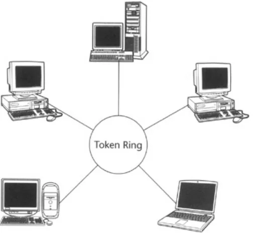
being transmitted sequentially from one ring station to the next. IBM pursued standardization of Token Ring under the 802.5 Working Group of the Institute of Electrical and Electronics Engineers (IEEE). Today, Token Ring is the second most widely used LAN technology. Token Ring LANs provided higher speed than Ethernet, but they are far more costly than Ethernet. Personal computers (PCs) were the revolution of the mid−1970s. Many consider Altair 8800 released by Micro Instrumentation and Telemetry Systems, Inc. (MITS) in 1975 to be the first PC. In 1977, Apple Computers, Inc. introduced the Apple II, a PC with a color monitor, sound, and graphics. In 1977, Dennis Hayes invented a device called modulator demodulator (MODEM), which enabled computers to communicate with one another over the regular phone line. In 1980, IBM introduced the IBM PC, which soon became a standard in the enterprise market. PCs were much smaller in size than their predecessor minicomputers and the mainframes. PCs were small enough to be placed on a desk, whereas minicomputers still required at least an area equivalent to a refrigerator. In addition to their size, PCs were much cheaper and faster than their rival minicomputers. Companies rapidly started replacing old and noisy typewriters with quieter and slicker PCs. The networking equipment and standards were already present when PCs arrived in the market. LANs started proliferating within organizations.
During the 1980s, while the speed of LANs and PCs kept on growing, there was an increased interest among organizations in communicating with other organizations and interconnecting their offices using computers; meanwhile computer enthusiasts were also interested in reaching out to other computer users. Organizations and individuals started setting up bulletin board systems (BBS), which used modems and phone lines to connect to other computers, to communicate with their customers and individuals. BBSs offered a low−cost solution for sharing files. BBS systems provided a computer terminal look and feel to remote computers. A BBS system consists of a PC equipped with one or more modems each connected with a phone line using BBS communication software. A user willing to access the BBS needed a PC, a modem, and a phone line with appropriate BBS software. BBS systems were not very secure, however, and were extremely vulnerable to malicious attacks from hackers who tried to degrade the performance of BBS systems by keeping the system busy, and to fill up the disk space on BBS systems by uploading unnecessary files.
The growing need for a public data network was becoming clear, and in 1983 ARPANET was split into ARPANET and MILNET; the latter became integrated with the Defense Data Network (DOD private network). In 1986, the National Science Foundation funded NSFNet as a cross−country 56 Kbps backbone for the Internet. November 3, 1988, is known by many computer enthusiasts as Black Thursday. On this day, a computer virus, known as the worm, burrowed through the Internet, affecting almost 6,000 of the 60,000 hosts on the Internet. The growing demand for the NFSNet and ARPANET kept on increasing, and ARPANET finally decommissioned in 1989. NSF gave control of NFSNet to the private sector, allowing commercial use of NFSNet, the remaining ARPANET, and any commercial extensions of the Internet. The development of the Internet took off once it was allowed to be used commercially. In 1991, the World Wide Web (WWW) was released by the European Organization for Nuclear Research (CERN), changing the way we live our lives today.
networks started operating at higher and higher speeds. The physical medium was improved, the protocols were enhanced, and smaller network devices were designed that consumed less power and were more reliable. Today, most LANs use the Ethernet adapters and operate at speeds in the range of 10 to 100 megabits per second (Mbps). These LANs are normally connected to other bigger networks or Internets via broadband connections or private lines using asynchronous transfer mode (ATM), Frame Relay, or other technologies. ATM and Frame Relay are high−performance WAN protocols that share a transmission medium and are normally used in situations where a reliable network connectivity is desired.
Even with these advancements in computer networking, there is room for higher network speeds. Standards organizations and research labs are constantly working on developing even faster computers and the networks to connect them.
Network Types
Computers can be networked in many different ways, forming different types of networks. The networking type is normally determined by the intended use, size, and geography of the computers on the network. Some of the examples of different network types are peer−to−peer networks, local area networks, wide area networks, personal area networks, virtual private networks, and the Internet.
Peer−to−Peer Networks
A peer−to−peer network consists of two or more computers that are directly connected to one another (see Figure 1.1). Such computer networks are normally insecure and operate at higher speeds than other types of networks. However, peer−to−peer computer networks are usually not very flexible and have limited scope. Peer−to−peer networks are considered to be operating in secure environment if the peers (computers in the network) mutually trust each other and there is no fear of a successful intrusion by an adversary.
Figure 1.1: Peer−to−Peer Network
An example of a peer−to−peer network might be a home computer network or a home office computer network, where two or more computers are interconnected to share files or computer processing power.
Local Area Networks (LANs)
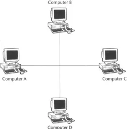
from honest mistakes by employees running a software virus on their computers to disgruntled employees who intentionally target a company's information assets.
Figure 1.2: LAN with more than two computers.
Wide Area Networks (WANs)
Depending on the technology used, LANs normally have a geographic limit of 100 meters. This is restrictive in terms of connecting two offices, which might be in two different cities. Wide area networks (WANs) take connectivity to a much higher level by enabling computers to connect with other computers or networks at much farther distances. A computer may be connected to a LAN thousands of miles away in a different city or perhaps a different continent. Two different LANs might be interconnected using a WAN link, which can exist over a phone line or a private leased line (see Figure 1.3). A WAN link is like a road between one place and another, busy place. The data exchanged over a WAN link is not considered to be secure unless it is transferred in an encrypted format (that is, data is encrypted before it is sent, and it is decrypted by the intended recipient upon receipt).
Figure 1.3: WAN link.
Personal Area Networks (PANs)
Personal area networks (PANs) are extremely low power, normally wireless, communication devices that enable a PAN−enabled device to exchange data with a PAN−aware device within a short distance (see Figure 1.4). Examples of such devices include handheld personal digital assistants (PDAs), human authentication devices, and payment systems. PANs are relatively new to the market. Lots of work is being done in this area to provide a higher level of information sharing and personal security.
Figure 1.4: PDA used in conjunction with a PC.
The Internet
The Internet in all its guises, permutations, and uses is extremely complex. But basically the Internet can be defined as a network of computer networks (see Figure 1.5). It can be thought of as a tree, where the Internet itself is the main trunk, networks connected to the Internet are branches, and the leaves on the branches are the computers on the Internet. The Internet uses TCP/IP as the protocol for exchanging data and information. In physical terms, the Internet is a global mesh of high−performance, high−bandwidth communications infrastructure consisting of a variety of communication equipment and connecting links (for example, copper cable, optical cables, satellites, and so on) together known as the Internet backbone. Access to this high−speed backbone is controlled by the major communication providers, which provide the access to the Internet Service Providers (ISPs). These ISPs resell the access to individuals and corporations for connectivity. This enables anyone with access to the Internet to reach anyone else who is also connected to the Internet.
Virtual Private Networks (VPNs)
Virtual private networks (VPNs; see Figure 1.6) are an extension of WANs. As mentioned earlier, WANs allow a computer to be connected to a remote LAN via a WAN link (where a WAN link can be over a phone line or a private leased line). The data exchanged over a WAN link can go through many computers and provide hackers and adversaries with a chance to eavesdrop and access this information, even altering it or using it for profit. A secure tunnel between the computer and the remote LAN is required to protect the information. The VPNs fit this requirement by allowing only authorized personnel access to the LAN. All the data is exchanged in an encrypted format so that it cannot be eavesdropped upon.
Figure 1.6: VPN connected to the Internet.
VPNs are becoming extremely popular. Most organizations that allow their employees to work remotely use a VPN connection over a WAN link instead of a raw WAN connection.
Network Topologies
Network topology refers to the shape of a network, or the network's layout. How different computers in a network are connected to each other and how they communicate is determined by the network's topology.
Three Commonly Used Topologies
The computers on a network can be arranged in many different ways, but the most commonly used topologies are bus, ring, and star.
Bus Topology
Figure 1.7: Bus topology.
In a bus topology all the devices have simultaneous access to the bus. The computer network must use a protocol to control such access to avoid collision and corruption of data. The most common type of such a protocol is Carrier Sense Multiple Access with Collision Detection (CSMA/CD), or Ethernet.
Ring Topology
The second most popular network topology is ring topology, in which each node acts as a repeater (see Figure 1.8). Transmission starts at a central station, usually the controller, and is sent to one node. That node receives the transmission, processes the information if needed, and then sends it to the next node on the ring. Long networks are possible because each node reconditions the transmission, and throughput time around the ring is predictable. When the ring breaks, communication is lost; hot swapping is not possible (a new node cannot be inserted in the ring while the network is in operation). All devices are connected to one another in the shape of a closed loop, so that each device is connected directly to two other devices, one on either side of it
Figure 1.8: Ring topology.
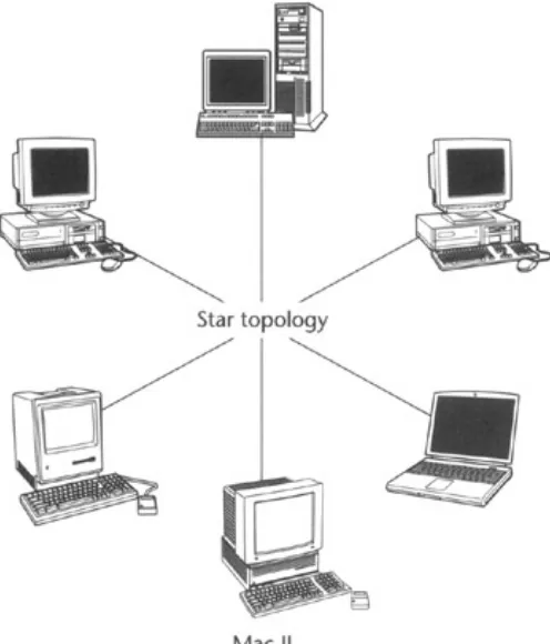
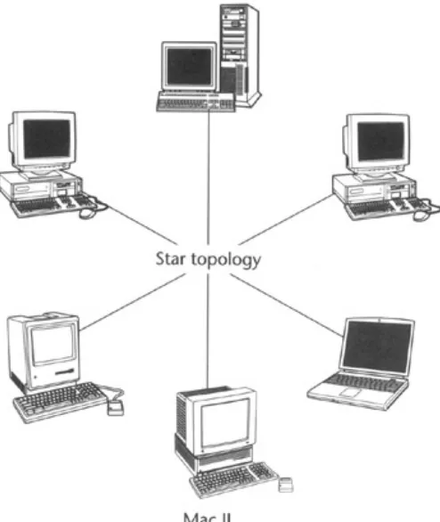
Star Topology
In a star topology, all devices are connected to a central hub (see Figure 1.9). Nodes communicate across the network by passing data through the hub. Because the protocol is easy to develop, many private networks use it. The mesh topology connects each node with every other node, creating an isolated data path between each node.
Figure 1.9: Star topology.
Star topology has a very high performance but works in a limited geographical area and is very costly, as the wires from each computer must run all the way to the central hub. Most wireless networks use a variation of the star topology (without wires, of course).
Choosing the Right Topology
Which topology you deploy should be based upon connectivity requirements, budget, and the available hardware. The bus topology is the simplest to implement and is the most widely used network topology. The ring topology is the most expensive to implement. Bus topology is extremely common in enterprise LANs; however, their backbones are often designed using the ring topology to give higher performance. Ring topology attains better performance over bus topology because the physical medium that data travels on is not shared among all computers on the network (only adjacent computers share the given medium), whereas in bus topology all computers connected to the network share the same physical medium, resulting in collision and medium congestion (network becomes too busy) and hence lower performance. Wireless LANs use the star topology because it provides a better management of the network bandwidth.
Network Hardware and Software
required for each computer in a network. For a network to function, all the computers must have compatible network software and hardware, and they must be connected to one another via a physical link, a cable, for example.
Networking Components
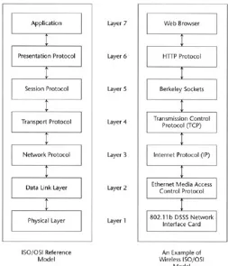
A computer in a network must have a network interface card (NIC) installed. These are electronic circuits that conform to the physical layer of the International Standards Organization Open Systems Interconnection (ISO/OSI) Reference Model and are IEEE−compliant. These network cards connect the computer to a network. In this section we discuss the ISO/OSI Reference Model and the IEEE view of the first two layers of this model. We also discuss NICs, hubs, routers, and repeaters.
International Standards Organization Open Systems Interconnection (ISO/OSI) Reference Model
Modern computer networks are designed in a highly structured way. To reduce the design complexity, most networks are organized as a series of layers, each one built upon its predecessor.
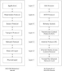
The ISO/OSI Reference Model (Figure 1.10) is based on a proposal developed by the International Standards Organization (ISO). The model is called ISO/OSI Reference Model because it deals with connecting open systems—that is, systems that are open for communication with other systems.
Figure 1.10: ISO/OSI Reference Model.
provides a better option to a network implementer who can build a network based upon his or her need. For example, today we use HyperText Transfer Protocol (HTTP) to surf the Internet. Let's assume that starting next week you would have to use a new protocol called ViperText Transfer Protocol (VTTP). If the protocol is written with ISO/OSI Reference Model in mind, all you would have to do is to install the VTTP protocol driver and you would be ready to use the VTTP without any other modification to your network hardware or software. The principles that were applied to arrive at the seven layers are as follows:
A layer should be created where a different level of abstraction is needed. 1.
Each layer should perform a well−defined function. 2.
The function of each layer should be chosen to interoperate with internationally standardized protocols.
3.
The number of layers should be large enough that distinct functions need not be thrown together in the same layer out of necessity, and small enough that the architecture does not become unwieldy.
4.
The computer systems that implement their network components using the ISO/OSI Reference Model can interoperate with most other systems. A layer can be replaced with another layer of the same type from a different vendor. This provides great flexibility to systems manufacturers, IT staff, and general users where they can plug and play different protocols, adapters, and networks without making drastic changes on their computers.
Now let's look at the layers that the OSI Reference Model defines.
The Application Layer: Layer 7
The application layer contains a variety of protocols that are commonly needed. For example, there are hundreds of incompatible terminal types in the world. Consider the plight of a full−screen editor that is supposed to work over a network with many different terminal types, each with different screen layouts, escape sequences for inserting and deleting text, ways of moving the cursor, and so on.
One way to solve this problem is to define an abstract network virtual terminal for which editors and other programs can be written. To handle each terminal type, a piece of software must be written to map the functions of the network virtual terminal onto the real terminal. For example, when the editor moves the virtual terminal's cursor to the upper left−hand corner of the screen, this software must issue the proper command sequence to the real terminal to get its cursor there too. All the virtual terminal software is in the application layer.
Another application layer function is file transfer. Different file systems have different file−naming conventions, different ways of representing text lines, and so on. Transferring a file between two different systems requires handling these and other incompatibilities. This work, too, belongs to the application layer, as do electronic mail, remote job entry, directory lookup, and various other general−purpose and special−purpose facilities.
The Presentation Layer: Layer 6
A typical example of a presentation service is encoding data in a standard, agreed−upon way. Most user programs do not exchange random binary bit strings. They exchange things such as people's names, dates, amounts of money, and invoices. These items are represented as character strings, integers, floating−point numbers, and data structures composed of several simpler items. Different computers have different codes for representing character strings, integers, and so on. In order to make it possible for computers with different representations to communicate, the data structures to be exchanged can be defined in an abstract way, along with a standard encoding to be used "on the wire." The job of managing these abstract data structures and converting from the representation used inside the computer to the network standard representation is handled by the presentation layer.
The presentation layer is also concerned with other aspects of information representation. For example, data compression can be used here to reduce the number of bits that have to be transmitted, and cryptography is frequently required for privacy and authentication.
The Session Layer: Layer 5
The session layer allows users on different machines to establish sessions between them. A session allows ordinary data transport, as does the transport layer, but it also provides some enhanced services useful to an application. A session might be used to allow a user to log into a remote time−sharing system or to transfer a file between two machines.
One of the services of the session layer is to manage dialogue control. Sessions can allow traffic to go in both directions at the same time, or in only one direction at a time. If traffic can go only one way at a time, the session layer can help keep track of whose turn it is.
A related session service is token management. For some protocols, it is essential that both sides do not attempt the same operation at the same time. To manage these activities, the session layer provides tokens that can be exchanged. Only the side holding the token may perform the critical operation.
Another session service is synchronization. Consider the problems that might occur when trying to do a two−hour file transfer between two machines on a network with a one−hour mean time between crashes. After each transfer was aborted, the whole transfer would have to start over again, and would probably fail again with the next network crash. To eliminate this problem, the session layer provides a way to insert checkpoints into the data stream, so that after a crash, only the data after the last checkpoint has to be repeated.
The Transport Layer: Layer 4
The basic function of the transport layer is to accept data from the session layer, split it up into smaller units if need be, pass these to the network layer, and ensure that the pieces all arrive correctly at the other end. Furthermore, all this must be done efficiently and in a way that isolates the session layer from the inevitable changes in the hardware technology.
The transport layer also determines what type of service to provide to the session layer, and ultimately, the users of the network. The most popular type of transport connection is an error−free point−to−point channel that delivers messages in the order in which they were sent. However, we have other possible kinds of transport, service, and transport−isolated messages with no guarantee about the order of delivery, and broadcasting of messages to multiple destinations. The type of service is determined when the connection is established.
The transport layer is a true source−to−destination or end−to−end layer. In other words, a program on the source machine carries on a conversation with a similar program on the destination machine, using the message headers and control messages.
Many hosts are multiprogrammed, which implies that multiple connections will be entering and leaving each host. There needs to be a way to tell which message belongs to which connection. The transport header is one place this information could be put.
In addition to multiplexing several message streams onto one channel, the transport layer must take care of establishing and deleting connections across the network. This requires some kind of naming mechanism so that a process on one machine has a way of describing with whom it wishes to converse. There must also be a mechanism to regulate the flow of information so that a fast host cannot overrun a slow one. Flow control between hosts is distinct from flow control between switches, although similar principles apply to both.
The Network Layer: Layer 3
The network layer is concerned with controlling the operation of the subnet. A key design issue is determining how packets are routed from source to destination. Routes could be based on static tables that are "wired into" the network and rarely changed. They could also be determined at the start of each conversation—for example, a terminal session. Finally, they could be highly dynamic, being determined anew for each packet, to reflect the current network load.
If too many packets are present in the subnet at the same time, they will get in each other's way, forming bottlenecks. The control of such congestion also belongs to the network layer.
Since the operators of the subnet may well expect remuneration for their efforts, there is often some accounting function built into the network layer. At the very least, the software must count how many packets, characters, or bits each customer sends, to produce billing information. When a packet crosses a national border, with different rates on each side, the accounting can become complicated.
When a packet has to travel from one network to another to get to its destination, many problems can arise. The addressing used by the second network may be different from the first one. The second one may not accept the packet at all because it is too large. The protocols may differ, and so on. It is up to the network layer to overcome all these problems to allow heterogeneous networks to be interconnected.
In broadcast networks, the routing problem is simple, so the network layer is often thin or even nonexistent.
The Data−Link Layer: Layer 2
sequentially, and process the acknowledgment frames sent back by the receiver. Since the physical layer merely accepts and transmits a stream of bits without any regard to meaning of structure, it is up to the data−link layer to create and recognize frame boundaries. This can be accomplished by attaching special bit patterns to the beginning and end of the frame. If there is a chance that these bit patterns might occur in the data, special care must be taken to avoid confusion.
The data−link layer should provide error control between adjacent nodes.
Another issue that arises in the data−link layer (and most of the higher layers as well) is how to keep a fast transmitter from drowning a slow receiver in data. Some traffic regulation mechanism must be employed in order to let the transmitter know how much buffer space the receiver has at the moment. Frequently, flow regulation and error handling are integrated for convenience.
If the line can be used to transmit data in both directions, this introduces a new complication that the data−link layer software must deal with. The acknowledgment frames for A to B traffic compete for the use of the line with the data frames for the B to A traffic. A clever solution (piggybacking) has been devised.
The Physical Layer: Layer 1
The physical layer is concerned with transmitting raw bits over a communication channel. The design issues have to do with making sure that when one side sends a 1 bit, it is received by the other side as a 1 bit, not as a 0 bit. Typical questions here are how many volts should be used to represent a 1 and how many for a 0, how many microseconds a bit lasts, whether transmission may proceed simultaneously in both directions, how the initial connection is established and how it is torn down when both sides are finished, and how many pins the network connector has and what each pin is used for. The design issues here deal largely with mechanical, electrical, and procedural interfaces, and the physical transmission medium, which lies below the physical layer. Physical layer design can properly be considered to be within the domain of the electrical engineer.
IEEE's View of the ISO/OSI Reference Model
The Institute of Electrical and Electronics Engineers (IEEE) has subdivided both the data−link layer and the physical layer into sublayers to attain a higher level of interoperability between devices (Figure 1.11).
Figure 1.11: IEEE's ISO/OSI subdivision.
The physical layer is subdivided into the physical layer convergence procedure (PLCP) and the physical medium dependent (PMD).
PLCP properly maps the MAC−specified data to the format that can be understood by the PMD layer and vice versa. The PMD layer provides the point−to−point communications between computers in the network. For example, on an Ethernet network, PMD on the network card communicates with PMDs of other network cards to establish communication between the computers.
IEEE's subdivision has enabled both software and hardware vendors to develop solutions that interoperate with each other and are easier to implement.
Network Interface Cards (NIC)
Hardware network adapters implement the physical layer of the OSI layer. Almost all computers today use one of the IEEE standard cards to add the networking functionality. The NICs are technically named after the IEEE standard that they follow along with the physical connectivity and type of media they use. For example, an Ethernet NIC works with a MAC adapter that knows how to format data for the IEEE 802.3 Ethernet standard. A twisted pair Ethernet adapter connects to the network with a twisted pair cable and follows the IEEE Ethernet standard. Commonly used network adapters include Ethernet NICs and Token Ring NICs.
Networking Cable and Physical Connections
In all wired networks, an NIC is connected with the network through NIC−supported connectors and cables. There are two major types of cables used with LANs, these are twisted pair cable and coaxial cable.
Twisted Pair Cable
Twisted pair cables (see Figure 1.12) are available both as shielded and unshielded. The cable has four pairs of wires inside the jacket. Each pair of wires is twisted with a different number of twists per inch to help eliminate interference from adjacent pairs and other electrical devices.
Figure 1.12: Twisted pair cable.
The tighter the cable is twisted, the higher the supported transmission rate and the greater the cost per foot. The Electronic Industry Association/Telecommunication Industry Association (EIA/TIA) have established standards for unshielded twisted pair (UTP) cables. There are five categories of UTP cables (see Table 1.1).
Table 1.1: The Five Twisted Pair Cable Categories
CATEGORY USE
2 Data up to 4 Mbps (LocalTalk) 3 Data up to 10 Mbps (Ethernet)
4 Data up to 20 Mbps (16 Mbps Token Ring) 5 Data up to 100 Mbps (Fast Ethernet)
When selecting the network cable, you should choose the best cable you can afford. This helps in upgrading the network in the future when faster technologies are available.
Unshielded twisted pair cables have the disadvantage of being susceptible to radio and electrical frequency interference. Shielded twisted pair is suitable for environments with electrical interference; however, the extra shielding can make the cables quite bulky. Shielded twisted pair is often used on networks using Token Ring topology.
Coaxial Cable
Coaxial cabling (see Figure 1.13) has a single copper conductor at its center. A plastic layer provides insulation between the center conductor and a braided metal shield. The metal shield helps to block any outside interference from fluorescent lights, motors, and other computers.
Figure 1.13: Coaxial cable.
Although coaxial cabling is difficult to install, it is highly resistant to signal interference. In addition, it can support greater cable lengths between network devices than twisted pair cable. The two types of coaxial cabling are thick coaxial and thin coaxial.
Thin coaxial cable is also referred to as thinnet. 10Base2 refers to the specifications for thin coaxial cable carrying Ethernet signals. The 2 in 10Base2 refers to the approximate maximum segment length, which is 200 meters. In actuality, the maximum segment length is 185 meters. Thin coaxial cable is popular in school networks, especially linear bus networks.
Thick coaxial cable is also referred to as thicknet. 10Base5 refers to the specifications for thick coaxial cable carrying Ethernet signals. The 5 in 10Base5 refers to the maximum segment length being 500 meters. Thick coaxial cable has an extra protective plastic cover that helps keep moisture away from the center conductor. This makes thick coaxial a great choice when running longer lengths in a linear bus network. One disadvantage of thick coaxial is that it does not bend easily and is difficult to install.
Hubs
Figure 1.14: Hub.
Hubs can be chained together to extend the number of computers participating on a network.
Routers
Routers (see Figure 1.15) restrict and route the network data traffic on a network. Consider a scenario where two different departments are interconnected with each other using the same network; assume that the two departments hardly need to communicate with each other. Because they both share the same network bandwidth, the networks get jammed and a little too busy. But if the network is divided into two separate networks and a router is put in between them, then the network is much cleaner and does not get clogged or too busy, as each department is concerned only with its own traffic and does not have to be concerned with the other's. Whenever data needs to be sent to the other department, the router acts as a network traffic controller and simply allows that data to pass through to the other network.
Figure 1.15: Router.
Routers, therefore, simplify the network and greatly improve the network performance.
Repeaters
Wired LANs can cover a limited geographical area, which usually ranges from 150 to about 300 meters with most wired networks. The maximum range that a LAN can cover depends upon the equipment and the type of cable used. Repeaters are a simple solution to overcome and extend the geographic limit. The reason for the limited area that LANs cover lies in the fact that electrical signals become weaker as they travel on a medium. Repeaters are devices that act like a relay station and strengthen an incoming weak electrical signal, without any alteration in the data that signal carries, and retransmit the data for further use. Repeaters should be placed at distances whenever a weaker signal is detected. In most networks, repeaters are needed at every 150 to 300 meters.
Networking Software
network software includes the proper network protocols and the NIC drivers.
A common example of the application software one might want to use would be a Web browser. A Web browser uses the network software to communicate with another computer and displays the results of the communication.
The networking protocols identify the computer and the user on a network to another computer and user. The most widely used network protocol is Transmission Control Protocol/Internet Protocol, or TCP/IP (see the next section on TCP/IP), which is also used on the Internet.
NIC drivers are normally devised by the NIC manufacturer and are set according to their specifications. Network drivers must be made compatible with the operating system. Network drivers communicate both with the networking protocols and the LLC to facilitate the data transmission over the wire.
Networking Protocol: TCP/IP
Networking protocols provide computer application software to access the network. These protocols provide an abstraction of the computer hardware, operating system, and physical characteristics of the network.
As already mentioned, TCP/IP is by far the most commonly used protocol, so its basic operation bears some examination. Many of the overall principles used in this protocol apply to other types of protocols. As a result of the explosive growth that the Internet has seen over the past decade, TCP/IP has become the de facto standard protocol for networking. Most vendors have dropped their proprietary protocols and adopted TCP/IP as the protocol for their networking software. (WAP is irrelevant for this discussion. This book is about 802.11b, which is essentially wireless Ethernet.)
With the growth of the Internet this address space is rapidly being depleted and there is need for a wider address space. As a response to this demand, IPv6, which has a 32−bit address space, has been developed.
The basic parameters of a TCP/IP network include IP address, subnet mask, Internet naming and domain name servers, default gateway, and IP routing. The next sections discuss each of these.
IP Address
Each computer participating on a TCP/IP network must have a unique IP address. An IP address in an IPv4 is a 32−bit number represented as a set of four bytes, with each number ranging from 0 to 255. The IP address is normally represented as set of four numbers separated by a period. This format is known as the dotted decimal format. For example, 192.168.0.2 is an IP address in the dotted decimal format.
For a computer to participate on the Internet it must have a unique IP address. The IP addresses to be used on the Internet were originally assigned by the Internet Network Information Center, or InterNIC, which was operated on behalf of the National Science Foundation (NSF) by Network Solutions Inc. (NSI). NSI was formed under a five−year contract granted in 1993 to assign Internet names and addresses and educate the general public about the Internet. Since April 1998, the IP address space, and all TCP/IP−related numbers, has historically been managed by the Internet Assigned Numbers Authority (IANA), a nonprofit industry organization (http://www.iana.org/), under the auspices of the U.S. Department of Commerce, which now holds the authority over the Internet. (For more information, go to http://www.internic.net/.) IANA generally allocates IP addresses to the service providers and large organizations. When the IP address scheme was initially proposed, the IP address space was divided into three classes of addresses used in IP−based networks. These classes were known as class A, B, and C. Each was intended for use with a different size of network, with each class A network capable of having 16,581,373 addresses or 1/255 of the total address space. There were also some addresses set aside for those networks that were not connected directly to the Internet. These are also known as unrouted networks. With the explosive growth of the Internet, this address allocation scheme resulted in a severe shortage of addresses for the newcomers and excessive waste for the ones who had registered addresses earlier. This resulted in the reallocation of address space and a new system of managing the addresses. IANA now allocates addresses only to very large organizations and service providers, who in turn allocate addresses to their subscribers in their address space. Typically service providers provide their subscribers with a small set of addresses that are typically assigned to the routers and firewalls connected directly to the Internet. Most of the computers inside a private network use the unrouted address internally and connect to the Internet through firewalls. There is also an address class called class D that is reserved for multicasting; for our purposes, we do not need to know about this type.
Figure 1.16: Address classes.
Subnet Mask
Subnet masks are used to efficiently utilize the IP addresses within a LAN. Address masks consist of binary 1s in the positions that contain the network address and binary Os in the positions that contain the hostid. The routers remember the subnet mask. All IP packets are routed based on the IP address and the subnet mask. For example, a subnet mask of 255.255.255.0, when combined with an IP address of 192.168.0.2, helps the router to properly route the IP packet.
Internet Naming and Domain Name Servers
It can be extremely difficult to remember all the numerical host IP addresses with which you might want to communicate. Instead, TCP/IP supports host naming, which allows an Internet name to be associated with an IP address; these names are called host names or the domain host names. For example, www.wiley.com is the domain host name of this book's publisher, John Wiley and Sons—the name corresponds to the numerical address, and both are stored in databases called domain name servers. TCP/IP includes special support for looking up IP addresses for the host names and vice versa. In order to correctly address a computer using a host name, a valid DNS must be configured under the IP settings on a computer, and those DNS servers must be available and accessible when IP address lookup is desired.
Default Gateway
Default gateway is the term used for identifying the router available on a network. All local LAN traffic must go through the router to reach another part of the LAN or the Internet. IP packets originating at a LAN are received by the gateway, and the gateway properly routes the IP address to the intended LAN.
IP Routing
With a limited number of IP addresses available, it was important to use a scheme to efficiently utilize the IP address pool. Routers with subnet masks are used to accomplish this purpose. Routers are used to separate logical networks and are assigned the netid as their IP addresses. All the hosts, which reside inside the router's domain, are required to use the IP address from the same netid host pool.